EP1215939B2 - Heizgefässe für Flüssigkeiten - Google Patents
Heizgefässe für Flüssigkeiten Download PDFInfo
- Publication number
- EP1215939B2 EP1215939B2 EP01310162A EP01310162A EP1215939B2 EP 1215939 B2 EP1215939 B2 EP 1215939B2 EP 01310162 A EP01310162 A EP 01310162A EP 01310162 A EP01310162 A EP 01310162A EP 1215939 B2 EP1215939 B2 EP 1215939B2
- Authority
- EP
- European Patent Office
- Prior art keywords
- vessel
- conduction member
- heat conduction
- base
- base member
- Prior art date
- Legal status (The legal status is an assumption and is not a legal conclusion. Google has not performed a legal analysis and makes no representation as to the accuracy of the status listed.)
- Expired - Lifetime
Links
Images


Classifications
-
- A—HUMAN NECESSITIES
- A47—FURNITURE; DOMESTIC ARTICLES OR APPLIANCES; COFFEE MILLS; SPICE MILLS; SUCTION CLEANERS IN GENERAL
- A47J—KITCHEN EQUIPMENT; COFFEE MILLS; SPICE MILLS; APPARATUS FOR MAKING BEVERAGES
- A47J27/00—Cooking-vessels
- A47J27/21—Water-boiling vessels, e.g. kettles
- A47J27/21008—Water-boiling vessels, e.g. kettles electrically heated
- A47J27/21041—Water-boiling vessels, e.g. kettles electrically heated with heating elements arranged outside the water vessel
-
- A—HUMAN NECESSITIES
- A47—FURNITURE; DOMESTIC ARTICLES OR APPLIANCES; COFFEE MILLS; SPICE MILLS; SUCTION CLEANERS IN GENERAL
- A47J—KITCHEN EQUIPMENT; COFFEE MILLS; SPICE MILLS; APPARATUS FOR MAKING BEVERAGES
- A47J27/00—Cooking-vessels
- A47J27/21—Water-boiling vessels, e.g. kettles
- A47J27/21008—Water-boiling vessels, e.g. kettles electrically heated
- A47J27/21058—Control devices to avoid overheating, i.e. "dry" boiling, or to detect boiling of the water
- A47J27/21083—Control devices to avoid overheating, i.e. "dry" boiling, or to detect boiling of the water with variable operating parameters, e.g. temperature or boiling period
-
- A—HUMAN NECESSITIES
- A47—FURNITURE; DOMESTIC ARTICLES OR APPLIANCES; COFFEE MILLS; SPICE MILLS; SUCTION CLEANERS IN GENERAL
- A47J—KITCHEN EQUIPMENT; COFFEE MILLS; SPICE MILLS; APPARATUS FOR MAKING BEVERAGES
- A47J27/00—Cooking-vessels
- A47J27/21—Water-boiling vessels, e.g. kettles
- A47J27/21166—Constructional details or accessories
-
- H—ELECTRICITY
- H05—ELECTRIC TECHNIQUES NOT OTHERWISE PROVIDED FOR
- H05B—ELECTRIC HEATING; ELECTRIC LIGHT SOURCES NOT OTHERWISE PROVIDED FOR; CIRCUIT ARRANGEMENTS FOR ELECTRIC LIGHT SOURCES, IN GENERAL
- H05B3/00—Ohmic-resistance heating
- H05B3/20—Heating elements having extended surface area substantially in a two-dimensional [2D] plane, e.g. plate-heater
- H05B3/22—Heating elements having extended surface area substantially in a two-dimensional [2D] plane, e.g. plate-heater non-flexible
- H05B3/26—Heating elements having extended surface area substantially in a two-dimensional [2D] plane, e.g. plate-heater non-flexible heating conductor mounted on insulating base
- H05B3/262—Heating elements having extended surface area substantially in a two-dimensional [2D] plane, e.g. plate-heater non-flexible heating conductor mounted on insulating base the insulating base being an insulated metal plate
-
- H—ELECTRICITY
- H05—ELECTRIC TECHNIQUES NOT OTHERWISE PROVIDED FOR
- H05B—ELECTRIC HEATING; ELECTRIC LIGHT SOURCES NOT OTHERWISE PROVIDED FOR; CIRCUIT ARRANGEMENTS FOR ELECTRIC LIGHT SOURCES, IN GENERAL
- H05B3/00—Ohmic-resistance heating
- H05B3/78—Heating arrangements specially adapted for immersion heating
- H05B3/82—Fixedly-mounted immersion heaters
-
- H—ELECTRICITY
- H05—ELECTRIC TECHNIQUES NOT OTHERWISE PROVIDED FOR
- H05B—ELECTRIC HEATING; ELECTRIC LIGHT SOURCES NOT OTHERWISE PROVIDED FOR; CIRCUIT ARRANGEMENTS FOR ELECTRIC LIGHT SOURCES, IN GENERAL
- H05B2203/00—Aspects relating to Ohmic resistive heating covered by group H05B3/00
- H05B2203/021—Heaters specially adapted for heating liquids
Definitions
- the present invention relates to liquid heating vessels, and in particular to liquid heating vessels having sheathed heating elements attached to the underside of the base of the vessel to heat liquid in the vessel.
- thermoelectric heating vessel An example of such a liquid heating vessel is disclosed in EP-A-63665 (SEB) in the arrangement disclosed in that document, the heating element is mounted to the base of the liquid heating vessel via a heat diffusion plate of aluminium or a similar highly conductive metal.
- the heat diffusion plate acts to diffuse heat from the heating element over the base of the heating vessel.
- a thermally sensitive control is provided so as to prevent the heater overheating in the event that the vessel is switched on dry or boils dry.
- a thermally sensitive control is also mounted on the heat diffusion plate.
- DE-U-9102908.2 discloses a liquid heating vessel according to the preamble of claim 1.
- US A 270067 discloses an electric frying pan having a heated base.
- EP-A-0700654 discloses a liquid heating vessel having a peripheral step receiving an element.
- the effect of the heat diffusion plate is relatively limited, acting, in practice, to provide limited radial diffusion of heat from the heating element. Accordingly, it may effectively be dispensed with.
- means must be provided for permitting effective sensing of overheating of the heater in the event of a dry boil or switch on dry situation.
- the present invention provides a liquid heating vessel as claimed in claim 1.
- heat is transferred directly into the base of the liquid heating vessel without the need for a heat diffusion plate.
- a heat conduction member arranged over and in good thermal contact with the heating element, and also in thermal contact with the vessel base, allows heat to be conducted to a thermally sensitive control which can sense when the heater is overheating. It is important that the heat conduction member is in thermal contact both with the heating element and with the base of the heating vessel since during normal operation of the heater, the vessel base will act to keep the temperature of the heat conduction member plate at a lower temperature thereby preventing accidental operation of a control, mounted thereon during heating of liquid in the vessel.
- the heat conduction member comprises a strip or plate mounted over a portion of the heating element.
- the plate is preferably of a material having a high thermal conductivity, for example, of aluminium, copper, or alloys thereof.
- the conduction member plate need only engage a relatively small portion of the heating element in order to perform its function. Accordingly, in a preferred embodiment the heat conduction member need only engage a limited circumferential extent of the element. Typically, this will be less than 90°, preferably around 45° circumferentially of the heating element.
- the conduction member preferably extends over at least half the radial width of the portion of the heating element, and most preferably over the entire width of the portion. Indeed, in a preferred embodiment, the conduction member extends radially beyond the element and is attached to the vessel base beyond the element.
- the conduction member may be provided with suitable locating means for assisting its accurate location on the heater and vessel base.
- the locating means may engage with the heating element and/or the base of the vessel itself.
- the vessel base is dish shaped, and the conduction member extends at least partially up the side of the dish for location.
- a plurality of heat conduction members may be provided for receiving a plurality of thermal control means.
- a single conduction member comprises mounting locations for a plurality of thermally sensitive control means.
- the arrangement is adapted for use with a thermally sensitive control having a pair of thermally sensitive actuators.
- a thermally sensitive control having a pair of thermally sensitive actuators.
- An example of such a control is the Applicant's U17 or U18 control.
- the thermal conduction member preferably extends across the base of the heating vessel and engage with respective opposed portions of the heating element. The respective mounting locations for the control actuators are, therefore, linked by a central bridge of material.
- the conduction member may be apertured both to save material costs and to manage the heat flow within the member.
- the conduction member may be provided with apertures, eg slots, extending around the actuator mounting locations so as to prevent heat transfer into the central region of the vessel base, which is unnecessary, and concentrate heat in the region of the actuator mounting locations.
- the apertures are preferably slots and in one embodiment may be arcuate.
- the heat conduction member of the invention may also be provided with means for mounting a control thereon. Accordingly, the heat conduction member may be provided with one or more tabs or other mounting locations for a control.
- the heat conduction member is brazed or soldered in position on the element and heating vessel base.
- the conduction plate is preferably provided with one or more apertures which allows the escape of fluxes etc. during the bonding process.
- the element and the conduction member may be coated with solder paste and located together on the vessel base and the assembly then heated to solder the plate and element in position.
- the element and the conduction member could be form locked together eg by pressing to assist in location.
- the element is preferably formed such that its height is less than its width.
- it is generally triangular or trapezoidal in section and is provided with a flange at its base to increase its area of contact with the vessel base.
- the sheath of the heating element is of aluminium, and most preferably the wall thickness of the sheath is greater than 0.75mm, more preferably around 1mm to accommodate deformation in creating a flange as described above.
- the base member is preferably made from a material with a low thermal conductivity such as stainless steel.
- the base may be formed with a groove which receives the heating element, and the conduction member be arranged across the top of the heating element. In other embodiments, the base is formed with a peripheral step which receives the heating element.
- the groove or step and the element are sized such that the conduction member lies flush with the adjacent region of the base. This allows a substantially planar conduction member to be used.
- the conduction member extends substantially around the whole groove or step, although an opening may be provided to allow the cold tails of the heating element to project through.
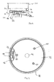
- a heated base 2 for mounting in the base of a plastics or metallic liquid heating vessel (not shown) is described for reference purposes only.
- the heated base 2 comprises a stainless steel base member 4 having a mounted flange 6 for mounting in the vessel body.
- the underside 8 of the base member 4 is dished, having a flat bottom surface 10.
- a generally triangular cross-sectioned annular aluminium sheathed heating element 12 is mounted around the periphery of the underside of the base member 4.
- a generally rectangular heat conduction member 14 is also mounted to the undersurface 10, extending completely across the undersurface 10 and over and around opposed portions 16 of the heating element 12.
- the heating element 12 is generally triangular in section and is formed with an aluminium sheath arranged around a heating wire and electrical insulating material in a known manner. Both the element 12 and the heater conduction member 14 are soldered onto the flat undersurface 10 as will be described further below.
- the heat conduction member 14 is formed as a strip of a thermally highly conductive material such as aluminium or copper or alloys thereof. In this particular embodiment it is formed of an aluminium strip about 1 mm in thickness.
- the conduction member comprises two end portions 20, 22 which engage over the heating element 12.
- the end portions 20, 22 are, therefore, formed into a shaped generally complementary to that of the heating element.
- the end regions 20, 22 are provided with respective locating lips 24, 26 which as can be seen in Figure 2 extend down over the side wall 28 of the underside 8 of the base member 4, thereby assisting in locating the conduction member 14 on the base member 4.
- the central region 30 of the heat conduction member 14 is provided with mounting locations 32, 34 for receiving bimetallic actuators 36 of a thermally sensitive control for the liquid heating vessel.
- the arrangement is intended for use with one of the Applicants U17 or U18 series of controls, whose mode of operation is described in detail in W095/34187 .
- Such controls comprise a pair of spaced apart bimetallic actuators 36 which sense the temperature of the base of a liquid heating vessel and operate in the event that they sense too high a temperature in order to interrupt the power supply to the heater of the vessel.
- the position of one such actuator 36 is shown in dotted line in figures for illustrative purposes.
- the mounting locations 32, 34 comprise respective apertures 38, 40 in the conduction member 14, surrounded by respective arcuate apertures 42, 44.
- the central apertures 38, 40 allow the satisfactory seating of the actuators 36 on the heat conduction member 14.
- the arcuate apertures 42, 44 serve to restrict the flow of heat from the mounting locations into the centre 30 of the conduction member 14 thereby assuring a faster response time in an overheat situation.
- thermally conductive member 14 is provided with a number of apertures 50 arranged over the rest of its surface. This acts to reduce material costs and, furthermore, will allow the escape of fluxes etc. during the manufacturing process as will be described further below.
- the conduction member 14 is also provided with mounting tabs 50 which may be used to mount the control to the conduction plate, thereby avoiding the need for any additional means of mounting for the control to the base member.
- the conduction member 14 and the element 12 are soldered to the underside 8 of the base member 4.
- the surface of the conduction plate 14 which faces the vessel base 4, and the element 14 may be coated with a suitable solder paste, the two components then assembled together onto the vessel base, which can then be heated to an appropriate temperature to melt the solder. Fluxes and excess solder can escape through the apertures 50 provided in the conduction plate 14 so as to provide a firm connection.
- the apertures 50 in the respective end regions 20, 22 of the heat conduction member allow fluxes to escape from between the heat conduction member 14 and the element 12.
- the base 2 is mounted in the bottom of a liquid heating vessel via its mounting flange 6 in a conventional manner.
- a thermally sensitive control e.g. an Applicant's U17 or U18 series control is then mounted to the heat conduction plate via the mounting lugs 54.
- the temperature of the mounting locations 32, 34 for the bimetallic actuators 36 of the thermally sensitive control will be kept relatively cool due the thermal contact of the conduction member 14 with the base member 4 in that region.
- heat will be conducted from the heating element 12 into the mounting location for the bimetals through the heat conduction member 14, and there will be no cooling effect through the base member 4.
- the mounting locations will reach a temperature sufficiently high to operate the bimetallic actuators 36 which will then act to disconnect the power supply to the heater.
- the heat conduction member may be adapted merely to receive a single bimetallic actuator or other form of control.
- the particular shape of the element may vary from that shown.
- Figure 7 shows an alternative geometry for the heater.
- the element 60 is formed with a mounting flange 62 at its base, to increase the surface area of contact with the base 8 of the vessel.
- the sheath will be made of aluminium, again typically with walls about 1 mm thick which will accommodate the pressing necessary to produce the mounting flange 62.
- the shape of the base member may also be different to that shown in Figures 1 to 6 .
- the base member 70 of an embodiment of the invention is deeper than that of the earlier described arrangement, and is provided with a peripheral step 72.
- An annular sheathed heating element 74 is brazed or otherwise secured into the step 72, as shown, preferably along both contact surfaces.
- a planar conduction member 76 of high thermal conductivity material is mounted over the lower surface of the heating element 74 and is brazed to the lowermost surface 78 of the base member 70 and also to the element 74.
- the conduction member is provide with studs 80 for mounting a control unit 84.
- the control unit 18 illustrated in this embodiment is one of the Applicant's U18 control units. As mentioned above, the control unit comprises a pair of bimetallic actuators which, when the control is mounted in position, are arranged in good thermal contact with the conduction member 76.
- the conduction member 76 is circular and covers substantially the entire base 70 apart from a central aperture 84 and a peripheral cut-out 86.
- the cut-out 86 allows the cold tails 88 of the heating element 74 to project below the conduction member 76 for connection to terminals 90 on the control unit 82.
- This embodiment works in the same manner as the earlier arrangement, with heat being transferred to the actuators of the control unit 82 in an overheat situation through the conduction member 76, but heat entering the base 70 directly from the heating element 74 through the walls of the step 72 of the base 70.
- Figure 10 shows a further embodiment of the invention.
- heating elements, 92, 94 are arranged in a step 96 of a base member 98.
- the upper element 92 is typically a higher power, main, heating element while the lower element 94 is a lower power, simmer, element.
- the two elements 92, 94 are brazed into the step 96 and preferably to each other.
- the conduction member 76 in the last two described embodiments may incorporate the various preferred features of the conduction member of the first arrangement. For example, they may extend only partially around the heating element(s). It may also incorporate features facilitating its attachment to the base member, for example small stand offs on its base facing surface to facilitate the distribution of braze during a brazing process.
- the invention may be applied to all manner of liquid heating vessels, for example kettles, coffee makers, deep fat fryers and so on.
Landscapes
- Engineering & Computer Science (AREA)
- Food Science & Technology (AREA)
- Cookers (AREA)
- Coating Apparatus (AREA)
- Resistance Heating (AREA)
- Instantaneous Water Boilers, Portable Hot-Water Supply Apparatuses, And Control Of Portable Hot-Water Supply Apparatuses (AREA)
- Thermally Insulated Containers For Foods (AREA)
- Surface Heating Bodies (AREA)
Claims (30)
- Flüssigkeitsheizgefäß mit einer Heizbasis, umfassend ein Basiselement (70; 98), ein ummanteltes elektrisches Heizelement (12; 74; 92, 94), welches direkt mit der Unterseite des Basiselements (70; 98) des Gefäßes verbunden ist zum Aufheizen einer in dem Gefäß enthaltenen Flüssigkeit, und ein Wärmeleitelement (14; 76), welches sich über einen Abschnitt des ummantelten Heizelements (12; 74; 92, 94) erstreckt und mit diesem in engem thermischen Kontakt ist und auch in engem thermischen Kontakt mit einem Abschnitt des Basiselements (70; 98) des Gefäßes angeordnet ist,
dadurch gekennzeichnet, dass das Basiselement (70; 98) mit einer Nut oder einer Umfangsstufe (72; 96) ausgebildet ist, wobei die Nut oder Umfangsstufe das Heizelement aufnimmt, und dass das Basiselement eine separate Komponente ist, welche in die Basis des Gefäßes eingebaut ist. - Gefäß nach Anspruch 1, wobei das Wärmeleitelement (14; 76) einen Streifen oder eine Platte umfasst, welche über einem Abschnitt des Heizelements angebracht ist.
- Gefäß nach Anspruch 1 oder 2, wobei das Wärmeleitelement (14; 76) ein Material mit einer hohen thermischen Leitfähigkeit wie z. B. Aluminium, Kupfer oder Legierungen von diesen ist.
- Gefäß nach einem vorhergehenden Anspruch, wobei die Wärmeleitelementplatte (14; 76) nur mit einer relativ kleinen Länge des Heizelements im Eingriff ist.
- Gefäß nach Anspruch 4, wobei das Wärmeleitelement (14; 76) mit weniger als 90°, vorzugsweise etwa 45° in Umfangsrichtung des Heizelements (12; 74; 92, 94) im Eingriff ist.
- Gefäß nach einem vorhergehenden Anspruch, wobei das Wärmeleitelement (14; 76) sich über wenigstens die Hälfte der radialen Breite des Heizelements (12; 74; 92, 94) erstreckt und höchst vorzugsweise über die gesamte Breite des Elements erstreckt.
- Gefäß nach Anspruch 6, wobei das Wärmeleitelement (14; 76) sich radial jenseits des Elements (12; 74; 92, 94) erstreckt und an dem Basiselement (70; 98) jenseits des Elements (12; 74; 92, 94) angebracht ist.
- Gefäß nach einem vorhergehenden Anspruch, wobei das Wärmeleitelement (14; 76) mit einem Anordnungsmittel versehen ist.
- Gefäß nach Anspruch 8, wobei das Gefäßbasiselement (70; 98) schalenförmig ist und das Anordnungsmittel des Wärmeleitelements (14; 76) sich wenigstens teilweise die Seite der Schale hinauf erstreckt.
- Gefäß nach einem vorhergehenden Anspruch, wobei ein einzelnes Leitelement (14; 76) Befestigungsstellen für eine Mehrzahl von thermisch sensitiven Steuer/Regelmitteln umfasst.
- Gefäß nach einem vorhergehenden Anspruch, wobei das Wärmeleitelement (14; 76) dafür bestimmt ist, ein oder mehrere bimetallische Stellelemente (36) von thermisch sensitiven Steuer/Regelmitteln aufzunehmen.
- Gefäß nach Anspruch 11, wobei das Leitelement (14; 76) ein Paar voneinander beabstandete Stellen (32, 34) zur Aufnahme eines Paars von thermisch sensitiven Stellelementen (36) umfasst, welche durch eine Materialbrücke (30) verbunden sind.
- Gefäß nach einem vorhergehenden Anspruch, wobei das Wärmeleitelement (14; 76) mit Öffnungen versehen ist.
- Gefäß nach Anspruch 13, wobei das Wärmeleitelement (14; 76) mit Öffnungen (38, 40) versehen ist, die sich um die Stellelementbefestigungsstelle (32, 34) erstrecken.
- Gefäß nach einem vorhergehenden Anspruch, wobei das Wärmeleitelement (14; 76) auch ein Mittel (50; 80) umfasst, um an diesem eine Steuerung/Regelung anzubringen.
- Gefäß nach Anspruch 15, wobei das Befestigungsmittel ein oder mehrere Laschen (50) umfasst.
- Gefäß nach einem vorhergehenden Anspruch, wobei das Wärmeleitelement (14; 76) in der richtigen Lage an das Element (12; 74; 92, 94) und das Basiselement (70; 98) hartgelötet oder gelötet ist.
- Gefäß nach Anspruch 17, wobei das Element (12; 74; 92, 94) auch auf das Basiselement (70; 98) hartgelötet oder gelötet ist.
- Gefäß nach einem vorhergehenden Anspruch, wobei das Element (12; 74; 92, 94) im Allgemeinen ringförmig ist und sich um den Umfang des Basiselements (70; 98) erstreckt.
- Gefäß nach einem vorhergehenden Anspruch, wobei das Element (12; 74; 92, 94) so ausgebildet ist, dass seine Höhe geringer als seine Breite ist.
- Gefäß nach einem vorhergehenden Anspruch, wobei das Element (12; 74; 92, 94) im Schnitt im Allgemeinen dreieckig oder trapezförmig ist.
- Gefäß nach einem vorhergehenden Anspruch wobei das Element (12; 74; 92, 94) mit einem Flansch an seiner Basis versehen ist, um seine Kontaktfläche mit dem Basiselement (70; 98) zu vergrößern.
- Gefäß nach einem vorhergehenden Anspruch, wobei die Ummantelung des Heizelements (12; 74; 92, 94) aus Aluminium besteht.
- Gefäß nach Anspruch 23, wobei die Dicke der Ummantelung größer als 0,75 mm, bevorzugt etwa 1 mm ist.
- Gefäß nach einem vorhergehenden Anspruch, wobei das Basiselement (70; 98) im Allgemeinen eben ist.
- Gefäß nach Anspruch 1, wobei das Leitelement (76) über die Oberseite des Heizelements (74; 92; 94) hinweg angeordnet ist.
- Gefäß nach Anspruch 26, wobei die Nut oder Stufe (72; 96) und das Element (74; 92, 94) so bemessen sind, dass das Leitelement (76) auf gleicher Höhe mit dem benachbarten Bereich des Basiselements (70; 98) liegt.
- Gefäß nach einem vorhergehenden Anspruch, wobei das Basiselement (70; 98) aus rostfreiem Stahl besteht.
- Flüssigkeitsheizgefäß nach einem vorhergehenden Anspruch, wobei der Körper des Flüssigkeitsheizgefäßes aus Kunststoff besteht.
- Flüssigkeitsheizgefäß nach einem vorhergehenden Anspruch, ferner umfassend eine thermisch sensitive Steuerung/Regelung (84) mit wenigstens einem thermisch sensitiven-Stellelement (32, 34), welches in thermischem Kontakt mit dem Leitelement (14; 76) angebracht ist.
Priority Applications (7)
| Application Number | Priority Date | Filing Date | Title |
|---|---|---|---|
| EP05006499A EP1565038B1 (de) | 2000-12-06 | 2001-12-05 | Heizgefässe für Flüssigkeiten |
| DE20218792U DE20218792U1 (de) | 2001-12-05 | 2002-12-04 | Heizgeräte mit mehreren Leistungsstufen |
| CNB021515654A CN100475103C (zh) | 2001-12-05 | 2002-12-05 | 多功率加热器 |
| CN02292861U CN2594719Y (zh) | 2001-12-05 | 2002-12-05 | 多功率加热器 |
| GB0511675A GB2412555B (en) | 2001-12-05 | 2002-12-05 | Multi-power heaters |
| GB0228460A GB2393372B (en) | 2001-12-05 | 2002-12-05 | Multi-power heaters |
| CNB2005101203269A CN100480595C (zh) | 2001-12-05 | 2002-12-05 | 液体加热容器的加热基座 |
Applications Claiming Priority (2)
| Application Number | Priority Date | Filing Date | Title |
|---|---|---|---|
| GBGB0029771.3A GB0029771D0 (en) | 2000-12-06 | 2000-12-06 | Liquid heating vessels |
| GB0029771 | 2000-12-06 |
Related Child Applications (1)
| Application Number | Title | Priority Date | Filing Date |
|---|---|---|---|
| EP05006499A Division EP1565038B1 (de) | 2000-12-06 | 2001-12-05 | Heizgefässe für Flüssigkeiten |
Publications (4)
| Publication Number | Publication Date |
|---|---|
| EP1215939A2 EP1215939A2 (de) | 2002-06-19 |
| EP1215939A3 EP1215939A3 (de) | 2002-12-04 |
| EP1215939B1 EP1215939B1 (de) | 2005-05-11 |
| EP1215939B2 true EP1215939B2 (de) | 2008-09-17 |
Family
ID=9904567
Family Applications (2)
| Application Number | Title | Priority Date | Filing Date |
|---|---|---|---|
| EP05006499A Expired - Lifetime EP1565038B1 (de) | 2000-12-06 | 2001-12-05 | Heizgefässe für Flüssigkeiten |
| EP01310162A Expired - Lifetime EP1215939B2 (de) | 2000-12-06 | 2001-12-05 | Heizgefässe für Flüssigkeiten |
Family Applications Before (1)
| Application Number | Title | Priority Date | Filing Date |
|---|---|---|---|
| EP05006499A Expired - Lifetime EP1565038B1 (de) | 2000-12-06 | 2001-12-05 | Heizgefässe für Flüssigkeiten |
Country Status (6)
| Country | Link |
|---|---|
| EP (2) | EP1565038B1 (de) |
| CN (2) | CN1670445B (de) |
| AT (2) | ATE434368T1 (de) |
| DE (3) | DE60110733T3 (de) |
| ES (1) | ES2216733T3 (de) |
| GB (1) | GB0029771D0 (de) |
Families Citing this family (6)
| Publication number | Priority date | Publication date | Assignee | Title |
|---|---|---|---|---|
| DE10112012A1 (de) * | 2001-03-07 | 2002-10-02 | Eichenauer Gmbh & Co Kg F | Heizeinsatz für ein elektrisch beheizbares Kochgefäß |
| GB0302537D0 (en) * | 2003-02-04 | 2003-03-12 | Strix Ltd | Electric heaters |
| GB0406428D0 (en) * | 2004-03-22 | 2004-04-21 | Strix Ltd | Heaters for liquid heating vessels |
| FR2876535B1 (fr) * | 2004-10-13 | 2006-12-01 | Seb Sa | Element chauffant |
| DE102009042481B4 (de) * | 2009-09-24 | 2021-08-05 | Stiebel Eltron Gmbh & Co. Kg | Warmwassergerät |
| CN109091018A (zh) * | 2018-08-01 | 2018-12-28 | 安徽信息工程学院 | 智能微型加热器 |
Citations (1)
| Publication number | Priority date | Publication date | Assignee | Title |
|---|---|---|---|---|
| DE9102908U1 (de) † | 1991-03-11 | 1991-05-29 | Conti Elektra Heizelemente GmbH, 6483 Bad Soden-Salmünster | Elektrisch beheizbares Wassergefäß |
Family Cites Families (25)
| Publication number | Priority date | Publication date | Assignee | Title |
|---|---|---|---|---|
| DE1128062B (de) * | 1961-03-14 | 1962-04-19 | Eberle & Koehler K G | Vorrichtung zur Steuerung von Kochendwassergeraeten |
| US3826898A (en) * | 1973-11-28 | 1974-07-30 | Gen Electric | Border treatment of composite metal plate surface heating unit |
| CA1092634A (en) * | 1977-10-18 | 1980-12-30 | Trans-Canada Life-Ware Limited | Electric frying pan |
| US4264539A (en) * | 1979-12-12 | 1981-04-28 | Samuel Ray Dickenson | Liquid fuel vaporizer |
| LU83286A1 (fr) * | 1981-04-07 | 1983-03-24 | Seb Sa | Prise de temperature par thermistance pour element chauffant |
| DE3320474A1 (de) * | 1983-06-07 | 1984-12-13 | Forbach GmbH, 8740 Bad Neustadt | Waermetauscher fuer fluessige medien |
| DE3437347A1 (de) * | 1984-10-11 | 1986-04-24 | E.G.O. Elektro-Geräte Blanc u. Fischer, 7519 Oberderdingen | Rohrkoerper-heizeinheit |
| DE3711637A1 (de) * | 1987-04-07 | 1988-10-27 | Ego Elektro Blanc & Fischer | Elektro-heizgefaess |
| GB9302965D0 (en) * | 1993-02-15 | 1993-03-31 | Strix Ltd | Immersion heaters |
| GB2285710A (en) * | 1994-01-13 | 1995-07-19 | Strix Ltd | Liquid heating vessels |
| IN192511B (de) * | 1994-06-09 | 2004-04-24 | Strix Ltd | |
| DE4432074A1 (de) * | 1994-09-09 | 1996-03-14 | Kreck Edelstahl Gmbh | Elektrisch beheiztes Kochgeschirr und Verfahren zu seiner Herstellung |
| DE69520563T3 (de) * | 1994-12-13 | 2006-11-09 | Strix Ltd. | Gefässe zum erhitzen von flüssigkeiten |
| US6153859A (en) * | 1995-07-31 | 2000-11-28 | Strix Limited | Liquid heating vessels |
| GB9525947D0 (en) * | 1995-12-19 | 1996-02-21 | Strix Ltd | Heating elements |
| GB2316848B (en) * | 1996-08-27 | 2000-10-04 | Strix Ltd | Electric heaters |
| CN2285108Y (zh) * | 1997-01-23 | 1998-07-01 | 潮州市凯乐微波家电有限公司 | 一种电热壶 |
| DE19734960A1 (de) * | 1997-08-13 | 1999-02-18 | Ako Werke Gmbh & Co | Kochzone |
| GB9718109D0 (en) * | 1997-08-27 | 1997-10-29 | Strix Ltd | Electric heaters |
| GB2354145B (en) * | 1998-06-03 | 2002-10-30 | Strix Ltd | Liquid heating vessels |
| DE19825161A1 (de) * | 1998-06-05 | 1999-12-09 | Volz Abc Elektrogeraete | Gerät zum Erhitzen von Flüssigkeiten |
| GB9823435D0 (en) * | 1998-10-26 | 1998-12-23 | Strix Ltd | Liquid heating apparatus |
| DE19933013A1 (de) * | 1999-07-14 | 2001-02-01 | Valeo Klimasysteme Gmbh | PTC-Heizelement mit Heizzonen |
| CN2394398Y (zh) * | 1999-09-30 | 2000-08-30 | 隋志国 | 加热烘烤两用电热盘 |
| EP1201933B1 (de) * | 2000-10-25 | 2006-03-08 | Eichenauer Heizelemente GmbH & Co.KG | Pumpe mit einem beheizbaren Gehäuse |
-
2000
- 2000-12-06 GB GBGB0029771.3A patent/GB0029771D0/en not_active Ceased
-
2001
- 2001-12-05 ES ES01310162T patent/ES2216733T3/es not_active Expired - Lifetime
- 2001-12-05 DE DE60110733T patent/DE60110733T3/de not_active Expired - Lifetime
- 2001-12-05 AT AT05006499T patent/ATE434368T1/de not_active IP Right Cessation
- 2001-12-05 DE DE60139038T patent/DE60139038D1/de not_active Expired - Lifetime
- 2001-12-05 EP EP05006499A patent/EP1565038B1/de not_active Expired - Lifetime
- 2001-12-05 DE DE01310162T patent/DE01310162T1/de active Pending
- 2001-12-05 AT AT01310162T patent/ATE295675T1/de not_active IP Right Cessation
- 2001-12-05 EP EP01310162A patent/EP1215939B2/de not_active Expired - Lifetime
- 2001-12-06 CN CN200510065948.6A patent/CN1670445B/zh not_active Expired - Fee Related
- 2001-12-06 CN CN01138393.3A patent/CN1208993C/zh not_active Expired - Fee Related
Patent Citations (1)
| Publication number | Priority date | Publication date | Assignee | Title |
|---|---|---|---|---|
| DE9102908U1 (de) † | 1991-03-11 | 1991-05-29 | Conti Elektra Heizelemente GmbH, 6483 Bad Soden-Salmünster | Elektrisch beheizbares Wassergefäß |
Also Published As
| Publication number | Publication date |
|---|---|
| ES2216733T1 (es) | 2004-11-01 |
| EP1565038A1 (de) | 2005-08-17 |
| CN1670445A (zh) | 2005-09-21 |
| DE60110733D1 (de) | 2005-06-16 |
| EP1215939B1 (de) | 2005-05-11 |
| EP1565038B1 (de) | 2009-06-17 |
| DE60110733T3 (de) | 2009-03-19 |
| CN1670445B (zh) | 2010-05-26 |
| ATE295675T1 (de) | 2005-05-15 |
| GB0029771D0 (en) | 2001-01-17 |
| EP1215939A3 (de) | 2002-12-04 |
| ES2216733T3 (es) | 2005-11-16 |
| CN1208993C (zh) | 2005-06-29 |
| DE60110733T2 (de) | 2006-01-12 |
| DE60139038D1 (de) | 2009-07-30 |
| ATE434368T1 (de) | 2009-07-15 |
| CN1371236A (zh) | 2002-09-25 |
| DE01310162T1 (de) | 2004-10-21 |
| EP1215939A2 (de) | 2002-06-19 |
Similar Documents
| Publication | Publication Date | Title |
|---|---|---|
| EP2583036B1 (de) | Dickschicht-heizelemente | |
| EP0724766B1 (de) | Verbesserungen an elektrisch geheisste kochgefässe | |
| US6262398B1 (en) | Electrical cooking appliance, in particular deep fryer, comprising a flat heating element with screen-printer resistor | |
| EP1215939B2 (de) | Heizgefässe für Flüssigkeiten | |
| CN100475103C (zh) | 多功率加热器 | |
| EP1651009B1 (de) | Heizer für Heizgefässe für Flüssigkeiten | |
| GB2369037A (en) | Appliances for heating liquids and foodstuffs | |
| JP3698116B2 (ja) | 誘導加熱調理器用加熱プレート及び鍋 | |
| EP1445985A2 (de) | Elektrische Heizelemente | |
| EP1649791A2 (de) | Heizelement für Wasserkocher | |
| EP1462039B1 (de) | Elektrisches Gerät zum Kochen von Flüssigkeiten | |
| WO1997043873A1 (en) | Electric heaters | |
| JPH049941Y2 (de) | ||
| GB2379851A (en) | Improved protection against failure of planar heating elements | |
| JPH0137538Y2 (de) | ||
| WO1996019909A1 (en) | Electrical heating elements | |
| JP2005310565A (ja) | 電磁調理器 | |
| GB2348589A (en) | Die-cast heater having a boss providing a contact location for bimetallic actuator | |
| JPH11253320A (ja) | 加熱調理器 |
Legal Events
| Date | Code | Title | Description |
|---|---|---|---|
| PUAI | Public reference made under article 153(3) epc to a published international application that has entered the european phase |
Free format text: ORIGINAL CODE: 0009012 |
|
| AK | Designated contracting states |
Kind code of ref document: A2 Designated state(s): AT BE CH CY DE DK ES FI FR GB GR IE IT LI LU MC NL PT SE TR |
|
| AX | Request for extension of the european patent |
Free format text: AL;LT;LV;MK;RO;SI |
|
| PUAL | Search report despatched |
Free format text: ORIGINAL CODE: 0009013 |
|
| AK | Designated contracting states |
Kind code of ref document: A3 Designated state(s): AT BE CH CY DE DK ES FI FR GB GR IE IT LI LU MC NL PT SE TR |
|
| AX | Request for extension of the european patent |
Free format text: AL;LT;LV;MK;RO;SI |
|
| RIC1 | Information provided on ipc code assigned before grant |
Free format text: 7H 05B 3/26 A, 7H 05B 1/02 B, 7A 47J 27/21 B, 7H 01H 37/04 B, 7H 05B 3/82 B |
|
| 17P | Request for examination filed |
Effective date: 20030327 |
|
| 17Q | First examination report despatched |
Effective date: 20030521 |
|
| AKX | Designation fees paid |
Designated state(s): AT BE CH CY DE DK ES FI FR GB GR IE IT LI LU MC NL PT SE TR |
|
| EL | Fr: translation of claims filed | ||
| DET | De: translation of patent claims | ||
| GRAJ | Information related to disapproval of communication of intention to grant by the applicant or resumption of examination proceedings by the epo deleted |
Free format text: ORIGINAL CODE: EPIDOSDIGR1 |
|
| GRAP | Despatch of communication of intention to grant a patent |
Free format text: ORIGINAL CODE: EPIDOSNIGR1 |
|
| GRAP | Despatch of communication of intention to grant a patent |
Free format text: ORIGINAL CODE: EPIDOSNIGR1 |
|
| GRAS | Grant fee paid |
Free format text: ORIGINAL CODE: EPIDOSNIGR3 |
|
| GRAA | (expected) grant |
Free format text: ORIGINAL CODE: 0009210 |
|
| AK | Designated contracting states |
Kind code of ref document: B1 Designated state(s): AT BE CH CY DE DK ES FI FR GB GR IE IT LI LU MC NL PT SE TR |
|
| PG25 | Lapsed in a contracting state [announced via postgrant information from national office to epo] |
Ref country code: FI Free format text: LAPSE BECAUSE OF FAILURE TO SUBMIT A TRANSLATION OF THE DESCRIPTION OR TO PAY THE FEE WITHIN THE PRESCRIBED TIME-LIMIT Effective date: 20050511 Ref country code: LI Free format text: LAPSE BECAUSE OF FAILURE TO SUBMIT A TRANSLATION OF THE DESCRIPTION OR TO PAY THE FEE WITHIN THE PRESCRIBED TIME-LIMIT Effective date: 20050511 Ref country code: CH Free format text: LAPSE BECAUSE OF FAILURE TO SUBMIT A TRANSLATION OF THE DESCRIPTION OR TO PAY THE FEE WITHIN THE PRESCRIBED TIME-LIMIT Effective date: 20050511 Ref country code: BE Free format text: LAPSE BECAUSE OF FAILURE TO SUBMIT A TRANSLATION OF THE DESCRIPTION OR TO PAY THE FEE WITHIN THE PRESCRIBED TIME-LIMIT Effective date: 20050511 Ref country code: AT Free format text: LAPSE BECAUSE OF FAILURE TO SUBMIT A TRANSLATION OF THE DESCRIPTION OR TO PAY THE FEE WITHIN THE PRESCRIBED TIME-LIMIT Effective date: 20050511 |
|
| REG | Reference to a national code |
Ref country code: GB Ref legal event code: FG4D |
|
| REG | Reference to a national code |
Ref country code: CH Ref legal event code: EP |
|
| REG | Reference to a national code |
Ref country code: IE Ref legal event code: FG4D |
|
| REF | Corresponds to: |
Ref document number: 60110733 Country of ref document: DE Date of ref document: 20050616 Kind code of ref document: P |
|
| PG25 | Lapsed in a contracting state [announced via postgrant information from national office to epo] |
Ref country code: SE Free format text: LAPSE BECAUSE OF FAILURE TO SUBMIT A TRANSLATION OF THE DESCRIPTION OR TO PAY THE FEE WITHIN THE PRESCRIBED TIME-LIMIT Effective date: 20050811 Ref country code: DK Free format text: LAPSE BECAUSE OF FAILURE TO SUBMIT A TRANSLATION OF THE DESCRIPTION OR TO PAY THE FEE WITHIN THE PRESCRIBED TIME-LIMIT Effective date: 20050811 Ref country code: GR Free format text: LAPSE BECAUSE OF FAILURE TO SUBMIT A TRANSLATION OF THE DESCRIPTION OR TO PAY THE FEE WITHIN THE PRESCRIBED TIME-LIMIT Effective date: 20050811 |
|
| REG | Reference to a national code |
Ref country code: GB Ref legal event code: 732E |
|
| PG25 | Lapsed in a contracting state [announced via postgrant information from national office to epo] |
Ref country code: PT Free format text: LAPSE BECAUSE OF FAILURE TO SUBMIT A TRANSLATION OF THE DESCRIPTION OR TO PAY THE FEE WITHIN THE PRESCRIBED TIME-LIMIT Effective date: 20051019 |
|
| REG | Reference to a national code |
Ref country code: CH Ref legal event code: PL |
|
| REG | Reference to a national code |
Ref country code: ES Ref legal event code: FG2A Ref document number: 2216733 Country of ref document: ES Kind code of ref document: T3 |
|
| PG25 | Lapsed in a contracting state [announced via postgrant information from national office to epo] |
Ref country code: IE Free format text: LAPSE BECAUSE OF NON-PAYMENT OF DUE FEES Effective date: 20051205 Ref country code: CY Free format text: LAPSE BECAUSE OF FAILURE TO SUBMIT A TRANSLATION OF THE DESCRIPTION OR TO PAY THE FEE WITHIN THE PRESCRIBED TIME-LIMIT Effective date: 20051205 |
|
| PG25 | Lapsed in a contracting state [announced via postgrant information from national office to epo] |
Ref country code: LU Free format text: LAPSE BECAUSE OF NON-PAYMENT OF DUE FEES Effective date: 20051231 Ref country code: MC Free format text: LAPSE BECAUSE OF NON-PAYMENT OF DUE FEES Effective date: 20051231 |
|
| PLBI | Opposition filed |
Free format text: ORIGINAL CODE: 0009260 |
|
| PLAX | Notice of opposition and request to file observation + time limit sent |
Free format text: ORIGINAL CODE: EPIDOSNOBS2 |
|
| 26 | Opposition filed |
Opponent name: STIEBEL ELTRON GMBH & CO. KG Effective date: 20060213 Opponent name: EICHENAUER HEIZELEMENTE GMBH & CO.KG Effective date: 20060210 |
|
| ET | Fr: translation filed | ||
| NLR1 | Nl: opposition has been filed with the epo |
Opponent name: EICHENAUER HEIZELEMENTE GMBH & CO.KG Opponent name: STIEBEL ELTRON GMBH & CO. KG |
|
| PLAF | Information modified related to communication of a notice of opposition and request to file observations + time limit |
Free format text: ORIGINAL CODE: EPIDOSCOBS2 |
|
| REG | Reference to a national code |
Ref country code: IE Ref legal event code: MM4A |
|
| PLBB | Reply of patent proprietor to notice(s) of opposition received |
Free format text: ORIGINAL CODE: EPIDOSNOBS3 |
|
| APBP | Date of receipt of notice of appeal recorded |
Free format text: ORIGINAL CODE: EPIDOSNNOA2O |
|
| APAH | Appeal reference modified |
Free format text: ORIGINAL CODE: EPIDOSCREFNO |
|
| APBU | Appeal procedure closed |
Free format text: ORIGINAL CODE: EPIDOSNNOA9O |
|
| PGFP | Annual fee paid to national office [announced via postgrant information from national office to epo] |
Ref country code: ES Payment date: 20071217 Year of fee payment: 7 |
|
| PGFP | Annual fee paid to national office [announced via postgrant information from national office to epo] |
Ref country code: IT Payment date: 20071219 Year of fee payment: 7 |
|
| PUAH | Patent maintained in amended form |
Free format text: ORIGINAL CODE: 0009272 |
|
| STAA | Information on the status of an ep patent application or granted ep patent |
Free format text: STATUS: PATENT MAINTAINED AS AMENDED |
|
| 27A | Patent maintained in amended form |
Effective date: 20080917 |
|
| AK | Designated contracting states |
Kind code of ref document: B2 Designated state(s): AT BE CH CY DE DK ES FI FR GB GR IE IT LI LU MC NL PT SE TR |
|
| NLR2 | Nl: decision of opposition |
Effective date: 20080917 |
|
| NLR3 | Nl: receipt of modified translations in the netherlands language after an opposition procedure | ||
| PG25 | Lapsed in a contracting state [announced via postgrant information from national office to epo] |
Ref country code: ES Free format text: LAPSE BECAUSE OF FAILURE TO SUBMIT A TRANSLATION OF THE DESCRIPTION OR TO PAY THE FEE WITHIN THE PRESCRIBED TIME-LIMIT Effective date: 20081228 |
|
| PLAB | Opposition data, opponent's data or that of the opponent's representative modified |
Free format text: ORIGINAL CODE: 0009299OPPO |
|
| PG25 | Lapsed in a contracting state [announced via postgrant information from national office to epo] |
Ref country code: IT Free format text: LAPSE BECAUSE OF NON-PAYMENT OF DUE FEES Effective date: 20081205 |
|
| PGFP | Annual fee paid to national office [announced via postgrant information from national office to epo] |
Ref country code: TR Payment date: 20131203 Year of fee payment: 13 |
|
| REG | Reference to a national code |
Ref country code: FR Ref legal event code: PLFP Year of fee payment: 15 |
|
| PGFP | Annual fee paid to national office [announced via postgrant information from national office to epo] |
Ref country code: GB Payment date: 20151217 Year of fee payment: 15 |
|
| PGFP | Annual fee paid to national office [announced via postgrant information from national office to epo] |
Ref country code: NL Payment date: 20151217 Year of fee payment: 15 |
|
| PGFP | Annual fee paid to national office [announced via postgrant information from national office to epo] |
Ref country code: DE Payment date: 20151223 Year of fee payment: 15 |
|
| PGFP | Annual fee paid to national office [announced via postgrant information from national office to epo] |
Ref country code: FR Payment date: 20151231 Year of fee payment: 15 |
|
| REG | Reference to a national code |
Ref country code: DE Ref legal event code: R119 Ref document number: 60110733 Country of ref document: DE |
|
| REG | Reference to a national code |
Ref country code: NL Ref legal event code: MM Effective date: 20170101 |
|
| GBPC | Gb: european patent ceased through non-payment of renewal fee |
Effective date: 20161205 |
|
| PG25 | Lapsed in a contracting state [announced via postgrant information from national office to epo] |
Ref country code: NL Free format text: LAPSE BECAUSE OF NON-PAYMENT OF DUE FEES Effective date: 20170101 |
|
| REG | Reference to a national code |
Ref country code: FR Ref legal event code: ST Effective date: 20170831 |
|
| PG25 | Lapsed in a contracting state [announced via postgrant information from national office to epo] |
Ref country code: FR Free format text: LAPSE BECAUSE OF NON-PAYMENT OF DUE FEES Effective date: 20170102 |
|
| PG25 | Lapsed in a contracting state [announced via postgrant information from national office to epo] |
Ref country code: DE Free format text: LAPSE BECAUSE OF NON-PAYMENT OF DUE FEES Effective date: 20170701 Ref country code: GB Free format text: LAPSE BECAUSE OF NON-PAYMENT OF DUE FEES Effective date: 20161205 |
|
| PG25 | Lapsed in a contracting state [announced via postgrant information from national office to epo] |
Ref country code: TR Free format text: LAPSE BECAUSE OF NON-PAYMENT OF DUE FEES Effective date: 20161205 |