EP1213073A2 - Spannzylinder - Google Patents
Spannzylinder Download PDFInfo
- Publication number
- EP1213073A2 EP1213073A2 EP01116372A EP01116372A EP1213073A2 EP 1213073 A2 EP1213073 A2 EP 1213073A2 EP 01116372 A EP01116372 A EP 01116372A EP 01116372 A EP01116372 A EP 01116372A EP 1213073 A2 EP1213073 A2 EP 1213073A2
- Authority
- EP
- European Patent Office
- Prior art keywords
- compressed air
- cylinder jacket
- shaft
- cavity
- lines
- Prior art date
- Legal status (The legal status is an assumption and is not a legal conclusion. Google has not performed a legal analysis and makes no representation as to the accuracy of the status listed.)
- Withdrawn
Links
Images


Classifications
-
- B—PERFORMING OPERATIONS; TRANSPORTING
- B41—PRINTING; LINING MACHINES; TYPEWRITERS; STAMPS
- B41F—PRINTING MACHINES OR PRESSES
- B41F13/00—Common details of rotary presses or machines
- B41F13/08—Cylinders
- B41F13/22—Means for cooling or heating forme or impression cylinders
-
- B—PERFORMING OPERATIONS; TRANSPORTING
- B29—WORKING OF PLASTICS; WORKING OF SUBSTANCES IN A PLASTIC STATE IN GENERAL
- B29C—SHAPING OR JOINING OF PLASTICS; SHAPING OF MATERIAL IN A PLASTIC STATE, NOT OTHERWISE PROVIDED FOR; AFTER-TREATMENT OF THE SHAPED PRODUCTS, e.g. REPAIRING
- B29C43/00—Compression moulding, i.e. applying external pressure to flow the moulding material; Apparatus therefor
- B29C43/32—Component parts, details or accessories; Auxiliary operations
- B29C43/52—Heating or cooling
-
- B—PERFORMING OPERATIONS; TRANSPORTING
- B41—PRINTING; LINING MACHINES; TYPEWRITERS; STAMPS
- B41F—PRINTING MACHINES OR PRESSES
- B41F27/00—Devices for attaching printing elements or formes to supports
- B41F27/10—Devices for attaching printing elements or formes to supports for attaching non-deformable curved printing formes to forme cylinders
- B41F27/105—Devices for attaching printing elements or formes to supports for attaching non-deformable curved printing formes to forme cylinders for attaching cylindrical printing formes
-
- B—PERFORMING OPERATIONS; TRANSPORTING
- B29—WORKING OF PLASTICS; WORKING OF SUBSTANCES IN A PLASTIC STATE IN GENERAL
- B29C—SHAPING OR JOINING OF PLASTICS; SHAPING OF MATERIAL IN A PLASTIC STATE, NOT OTHERWISE PROVIDED FOR; AFTER-TREATMENT OF THE SHAPED PRODUCTS, e.g. REPAIRING
- B29C65/00—Joining or sealing of preformed parts, e.g. welding of plastics materials; Apparatus therefor
- B29C65/02—Joining or sealing of preformed parts, e.g. welding of plastics materials; Apparatus therefor by heating, with or without pressure
- B29C65/06—Joining or sealing of preformed parts, e.g. welding of plastics materials; Apparatus therefor by heating, with or without pressure using friction, e.g. spin welding
-
- B—PERFORMING OPERATIONS; TRANSPORTING
- B29—WORKING OF PLASTICS; WORKING OF SUBSTANCES IN A PLASTIC STATE IN GENERAL
- B29L—INDEXING SCHEME ASSOCIATED WITH SUBCLASS B29C, RELATING TO PARTICULAR ARTICLES
- B29L2031/00—Other particular articles
- B29L2031/767—Printing equipment or accessories therefor
Definitions
- the invention is directed to a clamping cylinder for receiving and fastening a cylindrical embossing mold with a structured surface, e.g. for the production of holograms, cinegrams, exelgrams for the Security technology or for decorative purposes, including an exterior Cylinder jacket, which is closed by means of a front cover and on one Shaft is mounted.
- a clamping cylinder for receiving and fastening a cylindrical embossing mold with a structured surface, e.g. for the production of holograms, cinegrams, exelgrams for the Security technology or for decorative purposes, including an exterior Cylinder jacket, which is closed by means of a front cover and on one Shaft is mounted.
- the invention is based on the knowledge that a significant Improvement in work results can be achieved can that the embossing mold as such to a temperature determined as optimal brought.
- the object of the invention is one To design clamping cylinders so that such tempering of the embossing mold is feasible, while at the same time simple attachment and Adjustment of the embossing shape on the clamping cylinder should be possible.
- the cylinder jacket is provided with a plurality of holes which through the Compressed air lines leading inside the cylinder jacket are connected, which in turn can be connected to a compressed air source, and inside the A cavity for a temperature control medium, which and circulating outlet lines is provided.
- the compressed air lines enforce the cavity for the temperature control medium, whereby a compact, cost-effective construction is feasible.
- the compressed air can be supplied through distribution lines that are in one of the covers closing the cylinder jacket can.
- the shaft is advantageously designed as a hollow shaft and has one Cavity for the supply and a cavity for the discharge of the temperature control medium on.
- a two-way introduction is advantageously arranged to supply and discharge the temperature control medium.
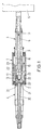
- An inventive clamping cylinder shown in the drawing comprises a cylinder jacket 1 for fastening one in the drawing Embossing shape shown, the cylinder jacket 1 with front covers 2, 3 is provided, which is penetrated by a rotatably mounted shaft 4 become. 4 is the fastening of the stuffing box 5 in the right Shaft recognizable, otherwise bearings are not shown.
- the shaft 4 has an inner cavity 6, with the one in FIG. 1 right side (see FIG. 3) through a feed pipe 7 (not shown in FIG. 1) a further cavity 8 to the shaft 4 is formed, whereby a continuous circulation of the temperature control medium is guaranteed.
- a commercially available one in itself Known two-way entry (gland 5) provided e.g. available at DEUBLIN GmbH.
- a tempering medium in particular Water
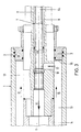
- the feed pipe 7 the inner cavity 6a and the inner cavity 6 of the shaft 4 in the direction of arrows 10 through the shaft 4 to guide, up to the front end shown in Fig. 2 11 of the inner cavity 6, from which channels 12 extend radially outwards extend and open into a cavity 13 which is between the central Section 14 of the shaft 4 and the cylinder jacket 1 is formed.
- the temperature control medium flows into the cylinder jacket 1 at a temperature Back in the direction of the arrows 15 until it reaches the end wall 16 of the cover 3, to from this area in the direction of arrow 17 through radial holes 18 to get into the cavity 8, where it is in the direction of the arrows 19th is returned in the shaft 4.
- the positioning of the embossing mold on the outside of the cylinder jacket is accomplished by compressed air that enters the space between the outside of the cylinder jacket 1 and the inside of the cylinder jacket 1 surrounding die from the left side in the drawing is supplied here, as shown in Fig. 1.
- the compressed air is introduced from the left through the cavity 20 and through radial bores 21 deflected outwards, which in the shaft 4 and the cover 2 are formed.
- the Lines 22 run with different axial extension in the Cavity 13.
- a radial bore 23 is provided in the cylinder jacket 1.
- the embossing mold is expanded in the elastic range and can then be over an air cushion is pushed onto the clamping cylinder or there in its position Getting corrected.
- the setting is done by the radial contraction the embossing mold after switching off the compressed air supply.
Landscapes
- Engineering & Computer Science (AREA)
- Mechanical Engineering (AREA)
- Moulds For Moulding Plastics Or The Like (AREA)
- Molds, Cores, And Manufacturing Methods Thereof (AREA)
- Holo Graphy (AREA)
- Actuator (AREA)
- Machines For Manufacturing Corrugated Board In Mechanical Paper-Making Processes (AREA)
- Shaping Metal By Deep-Drawing, Or The Like (AREA)
- Shaping Of Tube Ends By Bending Or Straightening (AREA)
Abstract
Description
- Fig. 1
- einen Längsschnitt durch einen erfindungsgemäßen Spannzylinder,
- Fig. 2
- eine vergrößerte Schnittdarstellung des linken Zentralbereiches in Fig. 1,
- Fig. 3
- eine vergrößerte Darstellung des rechten Zentralbereiches in Fig. 1 und
- Fig. 4
- eine vergrößerte Schnittdarstellung des rechten Außenbereiches in Fig. 1.
Claims (5)
- Spannzylinder zur Aufnahme und Befestigung einer zylindrischen Prägeform mit einer strukturierten Oberfläche, z.B. zum Herstellen von Hologrammen, umfassend einen äußeren Zylindermantel, der mittels stimseitiger Deckel verschlossen und auf einer Welle gelagert ist, dadurch gekennzeichnet, daßder Zylindermantel (1) mit einer Mehrzahl von Bohrungen (23, 23') versehen ist, die wenigstens teilweise mit durch das Innere des Zylindermantels (1) führende Druckluftleitungen (22) verbunden sind, die ihrerseits an eine Druckluftquelle anschließbar sind, undim Inneren des Zylindermantels (1) ein Hohlraum (13) für ein Temperiermedium, welches über Zu- und Auslaßleitungen (Hohlräume 6, 6a, 8) umgewälzt wird, vorgesehen ist.
- Spannzylinder nach Anspruch 1, dadurch gekennzeichnet, daß die Druckluftleitungen (22) den Hohlraum (13) für das Temperiermedium durchsetzen.
- Spannzylinder nach Anspruch 1, dadurch gekennzeichnet, daß die Druckluft durch Verteilungsleitungen (21) zugeführt wird, die in einem der den Zylindermantel (1) abschließenden Deckel (2) ausgebildet sind.
- Spannzylinder nach Anspruch 1, dadurch gekennzeichnet, daß die Welle (4) als Hohlwelle ausgebildet ist und einen Hohlraum (6, 6a) zur Zuführung und einen Hohlraum (8) zur Abführung des Temperiermediums aufweist.
- Spannzylinder nach Anspruch 1, dadurch gekennzeichnet, daß an dem Ende der Welle (4), welches dem Deckel (2) für die Druckluftzuführung gegenüberliegt, eine Zwei-Wege-Einführung (5) angeordnet ist.
Applications Claiming Priority (2)
| Application Number | Priority Date | Filing Date | Title |
|---|---|---|---|
| DE10039744 | 2000-08-16 | ||
| DE10039744A DE10039744B4 (de) | 2000-08-16 | 2000-08-16 | Spannzylinder zur Aufnahme und Befestigung einer zylindrischen Prägeform mit einer strukturierten Oberfläche |
Publications (2)
| Publication Number | Publication Date |
|---|---|
| EP1213073A2 true EP1213073A2 (de) | 2002-06-12 |
| EP1213073A3 EP1213073A3 (de) | 2006-09-20 |
Family
ID=7652420
Family Applications (1)
| Application Number | Title | Priority Date | Filing Date |
|---|---|---|---|
| EP01116372A Withdrawn EP1213073A3 (de) | 2000-08-16 | 2001-07-06 | Spannzylinder |
Country Status (6)
| Country | Link |
|---|---|
| US (1) | US6503074B2 (de) |
| EP (1) | EP1213073A3 (de) |
| JP (1) | JP2002061608A (de) |
| AU (1) | AU772958B2 (de) |
| CA (1) | CA2354499A1 (de) |
| DE (1) | DE10039744B4 (de) |
Cited By (1)
| Publication number | Priority date | Publication date | Assignee | Title |
|---|---|---|---|---|
| EP1745927A1 (de) | 2005-07-18 | 2007-01-24 | Hueck Folien GmbH & Co. KG | Druckzylinder mit abnehmbarer Prägeform |
Families Citing this family (5)
| Publication number | Priority date | Publication date | Assignee | Title |
|---|---|---|---|---|
| DE10049283A1 (de) * | 2000-10-05 | 2002-04-11 | Hueck Folien Gmbh & Co Kg | Verfahren und Vorrichtung zur Herstellung einer zylindrischen Prägeform |
| DE10304117A1 (de) | 2003-01-31 | 2004-08-05 | Giesecke & Devrient Gmbh | Spannzylinder zum Aufspannen zylindrischer Prägeformen für Prägewalzen |
| DE102004050984B3 (de) * | 2004-10-20 | 2006-07-06 | Hueck Folien Gmbh & Co. Kg | Verfahren zur Herstellung einer endlosen Nickelmatrize zum Prägen von strukturierten Oberflächen |
| CN107107518B (zh) * | 2014-12-04 | 2020-11-06 | 鲍勃斯脱梅克斯股份有限公司 | 旋转工具心轴、加工平的基板的加工单元、和操作方法 |
| CN106438565B (zh) * | 2016-12-08 | 2018-02-02 | 广东技术师范学院 | 一种防尘控热装置及其方法 |
Family Cites Families (16)
| Publication number | Priority date | Publication date | Assignee | Title |
|---|---|---|---|---|
| US2484670A (en) * | 1946-08-12 | 1949-10-11 | Barker Alfred Walter | Machine for molding plastic materials, such as confectionery |
| US2776452A (en) * | 1952-09-03 | 1957-01-08 | Chavannes Ind Synthetics Inc | Apparatus for embossing thermoplastic film |
| US3555601A (en) * | 1968-07-30 | 1971-01-19 | Harold Price | Apparatus for continuously forming conical shaped cleats on a thermoplastic sheet |
| CH604215A5 (de) * | 1976-12-21 | 1978-08-31 | Landis & Gyr Ag | |
| US4212609A (en) * | 1978-05-17 | 1980-07-15 | Fay Rudolph J | Method and apparatus for producing shaped and sized food articles |
| US4377336A (en) * | 1981-06-08 | 1983-03-22 | Bunnington Corporation | Heated pressure rolls |
| EP0196443B1 (de) * | 1985-03-29 | 1990-05-23 | Saueressig Gmbh & Co. | Tiefdruckzylinder, bestehend aus einem Kern und einer lösbar mit diesem verbundenen Hülse |
| DE3513136C1 (de) * | 1985-04-12 | 1986-08-28 | G. Siempelkamp Gmbh & Co, 4150 Krefeld | Kontinuierlich arbeitende Presse fuer die Herstellung von Laminaten |
| DE4108236C1 (en) * | 1991-03-14 | 1992-08-27 | Moebius & Ruppert Kg, 8520 Erlangen, De | Prodn. of highly accurate and/or polished surfaces - involves warming plastic component to plasticise and form it in press tool |
| DE4341262C2 (de) * | 1993-01-22 | 1999-04-08 | Heidelberger Druckmasch Ag | Vorrichtung für die Reduzierung von Materialausbuchtungen auf einer rohrförmigen Druckhülse |
| DE4338218C2 (de) * | 1993-11-09 | 1995-10-19 | Ralf Igler | Verfahren zur Herstellung eines Hologrammes oder Beugungsgitters sowie danach hergestelltes Hologramm oder Beugungsgitter |
| US5535674A (en) * | 1994-06-24 | 1996-07-16 | Heidelberger Druckmaschinen Ag | Distortion-reduced lithographic printing press |
| DE19510797A1 (de) * | 1995-03-24 | 1996-09-26 | Roland Man Druckmasch | Temperierbarer zylindrischer Rotationskörper |
| US5971738A (en) * | 1997-01-21 | 1999-10-26 | Velcro Industries B.V. | Continuous molding of fasteners and other features |
| US6074192A (en) * | 1997-09-11 | 2000-06-13 | Mikkelsen; Oeystein | Lenticular pattern forming roll and method for making the roll |
| DE19825223C2 (de) * | 1998-06-05 | 2000-11-30 | Fraunhofer Ges Forschung | Formwerkzeug und Verfahren zu dessen Herstellung |
-
2000
- 2000-08-16 DE DE10039744A patent/DE10039744B4/de not_active Expired - Fee Related
-
2001
- 2001-07-06 EP EP01116372A patent/EP1213073A3/de not_active Withdrawn
- 2001-07-23 JP JP2001221684A patent/JP2002061608A/ja active Pending
- 2001-08-01 CA CA002354499A patent/CA2354499A1/en not_active Abandoned
- 2001-08-02 AU AU57760/01A patent/AU772958B2/en not_active Ceased
- 2001-08-08 US US09/924,095 patent/US6503074B2/en not_active Expired - Fee Related
Cited By (1)
| Publication number | Priority date | Publication date | Assignee | Title |
|---|---|---|---|---|
| EP1745927A1 (de) | 2005-07-18 | 2007-01-24 | Hueck Folien GmbH & Co. KG | Druckzylinder mit abnehmbarer Prägeform |
Also Published As
| Publication number | Publication date |
|---|---|
| US20020022067A1 (en) | 2002-02-21 |
| EP1213073A3 (de) | 2006-09-20 |
| CA2354499A1 (en) | 2002-02-16 |
| AU5776001A (en) | 2002-02-21 |
| DE10039744A1 (de) | 2002-02-28 |
| DE10039744B4 (de) | 2008-06-05 |
| AU772958B2 (en) | 2004-05-13 |
| US6503074B2 (en) | 2003-01-07 |
| JP2002061608A (ja) | 2002-02-28 |
Similar Documents
| Publication | Publication Date | Title |
|---|---|---|
| DE102016102756B4 (de) | Regelzylinder für eine Regelarmatur und Regelarmatur mit einem derartigen Regelzylinder | |
| EP1620246B1 (de) | Mehrwellenextruder | |
| EP1577091B1 (de) | Rotationskörper einer Druckmaschine mit einem Ballen | |
| DE102018105048B4 (de) | Kraftstofftankherstellungsvorrichtung | |
| DE9000980U1 (de) | Walze für ein Glättwerk oder einen Kalander | |
| EP1475518A2 (de) | Buchse für ein Hydraulikventil | |
| DE202019105683U1 (de) | Extrusionstechnik zur Bildung von Kunststoff-Vorformlingen und Profilierungstechnik | |
| DE2166908B2 (de) | Kunststoffwarmverformungsmaschine zum Tiefziehen von einseitig offenen Hohlkörpern | |
| DE4111911A1 (de) | Walze | |
| DE10039744B4 (de) | Spannzylinder zur Aufnahme und Befestigung einer zylindrischen Prägeform mit einer strukturierten Oberfläche | |
| DE10250690B4 (de) | Rotationskörper einer Druckmaschine mit einem Ballen | |
| DE2539785B2 (de) | Heißkanalspritzdüse | |
| DE19941160B4 (de) | Zylinder für einen Schneckenextruder mit Kanälen für ein Temperiermedium | |
| DE102005000794A1 (de) | Vorrichtung und Verfahren zur Herstellung und/oder Veredelung einer Faserstoffbahn | |
| DE202004015229U1 (de) | Vorrichtung mit mehreren Walzen | |
| DE202019105681U1 (de) | Extrusionstechnik zur Bildung von Kunststoff-Vorformlingen und Schlauchbildungstechnik | |
| DE10250691B4 (de) | Rotationskörper einer Druckmaschine mit einem Grundkörper | |
| DE3637552C1 (en) | Device for cooling a mouth mould (neck ring) of a glass-moulding machine | |
| DE3909134C2 (de) | ||
| DE10316119A1 (de) | Verfahren und Vorrichtung zum Aushärten von Strängen aus Kleinteilen mit Bindemitteln nach einer Strangpresse | |
| EP1745927B1 (de) | Druckzylinder mit abnehmbarer Prägeform | |
| DE19903699A1 (de) | Formwerkzeug | |
| DE102016114706A1 (de) | Adapterplatte sowie Spritzgießmaschine mit einer solchen | |
| DE202019105685U1 (de) | Extrusionstechnik zur Bildung von Kunststoff-Vorformlingen und Drosseltechnik | |
| DE69618331T2 (de) | Ölzufuhrleitungenvorrichtung für eine durchbiegungseinstellwalze |
Legal Events
| Date | Code | Title | Description |
|---|---|---|---|
| PUAI | Public reference made under article 153(3) epc to a published international application that has entered the european phase |
Free format text: ORIGINAL CODE: 0009012 |
|
| AK | Designated contracting states |
Kind code of ref document: A2 Designated state(s): AT BE CH CY DE DK ES FI FR GB GR IE IT LI LU MC NL PT SE TR |
|
| AX | Request for extension of the european patent |
Free format text: AL;LT;LV;MK;RO;SI |
|
| PUAL | Search report despatched |
Free format text: ORIGINAL CODE: 0009013 |
|
| AK | Designated contracting states |
Kind code of ref document: A3 Designated state(s): AT BE CH CY DE DK ES FI FR GB GR IE IT LI LU MC NL PT SE TR |
|
| AX | Request for extension of the european patent |
Extension state: AL LT LV MK RO SI |
|
| 17P | Request for examination filed |
Effective date: 20061031 |
|
| AKX | Designation fees paid |
Designated state(s): AT BE CH LI |
|
| RBV | Designated contracting states (corrected) |
Designated state(s): AT CH DE LI |
|
| REG | Reference to a national code |
Ref country code: DE Ref legal event code: 8566 |
|
| RAP1 | Party data changed (applicant data changed or rights of an application transferred) |
Owner name: HUECK FOLIEN GES.M.B.H. |
|
| 17Q | First examination report despatched |
Effective date: 20080516 |
|
| STAA | Information on the status of an ep patent application or granted ep patent |
Free format text: STATUS: THE APPLICATION IS DEEMED TO BE WITHDRAWN |
|
| 18D | Application deemed to be withdrawn |
Effective date: 20080927 |