EP1211328A2 - Kippbarer Konverter mit Stützkonsolen und Gelenklager zur Montage - Google Patents
Kippbarer Konverter mit Stützkonsolen und Gelenklager zur Montage Download PDFInfo
- Publication number
- EP1211328A2 EP1211328A2 EP01126266A EP01126266A EP1211328A2 EP 1211328 A2 EP1211328 A2 EP 1211328A2 EP 01126266 A EP01126266 A EP 01126266A EP 01126266 A EP01126266 A EP 01126266A EP 1211328 A2 EP1211328 A2 EP 1211328A2
- Authority
- EP
- European Patent Office
- Prior art keywords
- converter
- support ring
- support
- vessel
- converter vessel
- Prior art date
- Legal status (The legal status is an assumption and is not a legal conclusion. Google has not performed a legal analysis and makes no representation as to the accuracy of the status listed.)
- Withdrawn
Links
- 230000015572 biosynthetic process Effects 0.000 claims abstract 2
- 230000005540 biological transmission Effects 0.000 claims description 3
- 238000010276 construction Methods 0.000 description 4
- 230000002349 favourable effect Effects 0.000 description 3
- 238000012423 maintenance Methods 0.000 description 3
- 238000005452 bending Methods 0.000 description 2
- 238000005516 engineering process Methods 0.000 description 1
- 238000004519 manufacturing process Methods 0.000 description 1
- 238000007363 ring formation reaction Methods 0.000 description 1
Images

Classifications
-
- C—CHEMISTRY; METALLURGY
- C21—METALLURGY OF IRON
- C21C—PROCESSING OF PIG-IRON, e.g. REFINING, MANUFACTURE OF WROUGHT-IRON OR STEEL; TREATMENT IN MOLTEN STATE OF FERROUS ALLOYS
- C21C5/00—Manufacture of carbon-steel, e.g. plain mild steel, medium carbon steel or cast steel or stainless steel
- C21C5/28—Manufacture of steel in the converter
- C21C5/42—Constructional features of converters
- C21C5/46—Details or accessories
- C21C5/4633—Supporting means
- C21C5/464—Trunnion bearings
-
- C—CHEMISTRY; METALLURGY
- C21—METALLURGY OF IRON
- C21C—PROCESSING OF PIG-IRON, e.g. REFINING, MANUFACTURE OF WROUGHT-IRON OR STEEL; TREATMENT IN MOLTEN STATE OF FERROUS ALLOYS
- C21C5/00—Manufacture of carbon-steel, e.g. plain mild steel, medium carbon steel or cast steel or stainless steel
- C21C5/28—Manufacture of steel in the converter
- C21C5/42—Constructional features of converters
- C21C5/46—Details or accessories
- C21C5/50—Tilting mechanisms for converters
Definitions
- the invention relates to a tiltable converter, comprising a converter vessel with a vertical axis and one surrounding it at a radial distance Support ring with two support pins diametrically opposite in a horizontal axis, the load transfer between the converter vessel and support ring via Fastening elements are carried out, which together form three force components, namely longitudinal fastening, transverse fastening and transverse locking.
- the design of the known converter is characterized in that at least six pendulum rods, preferably seven pendulum rods are provided. there is in the area of each trunnion approximately parallel to that of the support ring formed plane and approximately at right angles to the tilt axis formed by the support pin of the converter vessel directed pendulum rod provided.
- pendulum bars these are approximately parallel to the longitudinal axis aligned of the converter vessel and as close as possible to the trunnion provided, preferably in an angular range of 25 to 45 degrees, wherein the angle in the plan of the converter vessel, starting from the tilt axis, is measured.
- the design of the converter is characterized in that the Bearings that have pendulum rods passing through bolts, each bolt on both sides of the pendulum rod via support straps on the converter vessel or on the support ring is supported, wherein the support tabs are preferably welded to the converter vessel and are connected to the support ring by means of a screw connection.
- a disadvantage of the known design of the tiltable converter is the large one Number of bearings at the ends of the pendulum rods, as shown in Figures 1 and 2 a total of 14 bearings, which not only have a significant manufacturing technology Effort, but also a corresponding maintenance effort cause.
- DE-C-27 39 540 relates to the prior art and DE-A-29 31 671.
- Support is provided in these known converters the converter vessel on the support ring surrounding it by means of a link, which are at least partially designed as so-called "triangular links".
- a wishbone is to be understood as one that either on the converter vessel or on the support ring with one end by means of two spaced apart spherical bearing and with its other end on the support ring or on the converter vessel is articulated with a single spherical bearing.
- the object of the invention based on a type of a tiltable converter in the preamble of claim Specify 1 type mentioned, on the one hand, a positive connection between converter vessel and support ring results, but radial as well as axial Opposes deformations of the converter vessel with the lowest possible resistance, This results in a constraint-free construction and with a favorable type of stress the other supporting elements are maintenance-free, uncomplicated and Production-technically favorable execution allows, and the fasteners form three force components together, namely longitudinal fastening, Cross mounting and locking.
- the support brackets and the spherical bearings be articulated with two pairs of push-pull rods.
- An embodiment of the load transmission converter vessel / support ring is characterized in that that the transverse lock is located at the bottom of the support ring Formation of a joint with the hinge arranged with the converter vessel a horizontal axis.
- the converter according to the invention is further characterized in that the Cross-fastening a pair of load bolts arranged on the top of the support ring comprises, which is load-supported between stops of the converter vessel are.
- the converter according to the invention is characterized in that that the cross attachment is formed with a pair of push-pull rods which is articulated below the support ring to the converter vessel, in a spherical bearing on the one hand on the support ring, and on the other hand on Converter vessel are articulated.
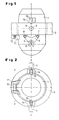
- the tiltable converter shown in Figures 1 and 2 with a vertical Axis x-x in a construction according to the invention comprises a converter vessel 1 and a support ring 2 surrounding this at a radial distance with two in a horizontal one Axis y-y diametrically opposite trunnions 3, 4, the Load transmission between converter vessel 1 and support ring 2 via articulated connections takes place, which together form three force components, namely longitudinal fastening, Cross fastening and cross locking, characterized in that the longitudinal fastening on the converter vessel 1 arranged below the support ring 2 Support brackets 6 and arranged on the underside of the support ring 2 at a distance Spherical bearings 7, 8, each with a triangle as a support member 9 are connectable.
- the support ring 2 and the converter vessel 1 also low degree of freedom interlocking transverse locking elements 10, 11 in Have shape of a hinge, which are designed such that they have a lateral Prevent the converter vessel 1 from tipping away relative to the support ring 2.
- the support member 9 is an approximately triangular flat material fitting, which with the support ring 2 by two spherical spherical bearings spaced apart on its circumference 7, 8, and with the converter vessel 1 by means of a respective spherical spherical bearing formed on a support bracket 6 articulated connected is.
- the converter shown in plan view in FIG. 2 comprises a converter vessel 1, surrounded at a radial distance from a support ring 2 on which a pair of support pins 3, 4 are attached in a diametrical position, the converter can be tilted about the y-y axis take up.
- Support ring 2 and converter vessel 1 are by transverse locking elements 10, 11 in Form of a hinge with the axis z-z hinged together.
- transverse forces between the converter vessel 1 and the support ring 2 due to tilting movements of the converter are additionally supported by load bolts 13 on the converter vessel 1 and these associated stops 14 on the support ring 2 to form a Lateral locking caught.
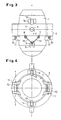
- FIGS. 3 and 5 A further embodiment according to the invention is shown in FIGS. 3 and 5 provides that the articulated connection between the support ring 2 and converter vessel 1 can also have two push-pull rods 15, 15 'which on the one hand with the support ring 2 at two spaced-apart spherical spherical bearings 7, 8, and on the other hand with a spherical bearing assigned to them at a vertical distance are articulated to a support bracket 6 of the converter vessel 1.
- Figure 4 shows an embodiment of the invention with a double arrangement of the locking elements 10, 11 opposite each other. This version has proven to be particularly robust and resilient. In contrast, the design of the Converter according to Figure 6 is particularly simple and inexpensive and is suitable for versions with a comparatively low converter weight.
Landscapes
- Engineering & Computer Science (AREA)
- Chemical & Material Sciences (AREA)
- Manufacturing & Machinery (AREA)
- Materials Engineering (AREA)
- Metallurgy (AREA)
- Organic Chemistry (AREA)
- Carbon Steel Or Casting Steel Manufacturing (AREA)
Abstract
Description
- Längsbefestigung,
- Querbefestigung,
- Querarretierung,
- Fig. 1
- die Ansicht eines erfindungsgemäßen Konverters entlang einer vertikalen Achse,
- Fig. 2
- den Konverter gemäß Fig. 1 in Draufsicht,
- Fig. 3
- eine Ansicht des Konverters mit anderen Befestigungselementen,
- Fig. 4
- den Konverter gemäß Fig. 3 in Draufsicht,
- Fig. 5
- eine Ansicht des Konverters mit sowohl Querbefestigungs- als auch Querarretierungs-Elementen,
- Fig. 6
- den Konverter gemäß Fig. 5 in Draufsicht.
- 1
- Konvertergefäß
- 2
- Tragring
- 3
- Tragzapfen
- 4
- Tragzapfen
- 5
- Gelenklager
- 6
- Stützkonsole
- 7
- Gelenklager
- 8
- Gelenklager
- 9
- Stützglied
- 10
- Querarretierungselement, Scharnierbolzen
- 11
- Querarretierungselement, Scharnierarme
- 13
- Lastbolzen
- 14
- Anschläge
- 15, 15'
- Zug-Druck-Stange
- 16
- Zug-Druck-Stange
Claims (9)
- Kippbarer Konverter, umfassend ein Konvertergefäß (1) mit einer vertikalen Achse (x-x) und einen dieses in radialem Abstand umgebenden Tragring (2) mit zwei in einer horizontalen Achse (y-y) diametral gegenüberliegenden Tragzapfen (3, 4), wobei die Lastübertragung Konvertergefäß/Tragring über Befestigungselemente erfolgt, die miteinander drei Kraftkomponenten ausbilden, nämlich Längsbefestigung, Querbefestigung und Querarretierung, dadurch gekennzeichnet, dass die Längsbefestigung am Konvertergefäß (1) unterhalb des Tragringes (2) angeordnete Stützkonsolen (6) und an der Unterseite des Tragringes (2) im Abstand angeordnete Gelenklager (7, 8) umfasst, die mit je einem Gelenkdreieck als Stützglied (9) verbindbar sind.
- Konverter nach Anspruch 1, dadurch gekennzeichnet, dass die Stützkonsolen (6) und die Gelenklager (7, 8) mit je zwei Paaren von Zug-Druck-Stangen (15, 15') gelenkig verbindbar sind.
- Konverter nach einem der Ansprüche 1 oder 2, dadurch gekennzeichnet, dass die Querarretierung ein an der Unterseite des Tragringes (2) unter Ausbildung einer Gelenk-Verbindung mit dem Konvertergefäß (1) angeordnetes Scharnier (10, 11) mit einer horizontalen Achse (z-z) ist.
- Konverter nach einem oder mehreren der Ansprüche 1 bis 3, dadurch gekennzeichnet, dass die Querbefestigung ein Paar auf der Oberseite des Tragringes (2) angeordnete Lastbolzen (13) umfasst, die zwischen Anschlägen (14) des Konvertergefäßes (1) lastabstützbar geführt sind.
- Konverter nach Anspruch 4, dadurch gekennzeichnet, dass die Querbefestigung (11) mit jeweils einem Paar Zug-Druck-Stangen (16) ausgebildet ist, die unterhalb des Tragringes (2), diesen gelenkig mit dem Konvertergefäß (1) verbindbar, in je einem Gelenklager (7, 8) einerseits am Tragring (2), und andererseits am Konvertergefäß (1) angelenkt sind.
- Konverter nach einem oder mehreren der Ansprüche 1 bis 5, dadurch gekennzeichnet, dass das Stützglied (9) ein etwa dreieckiges Flachmaterial-Formstück ist, welches mit dem Tragring (2) durch zwei an seinem Umfang beabstandet angeordnete sphärische Gelenklager (7, 8), und mit dem Konverterbehälter (1) durch jeweils ein an diesem angeordnetes, an einer Stützkonsole (6) ausgebildetes sphärisches Gelenklager gelenkig verbunden ist.
- Konverter nach einem oder mehreren der Ansprüche 1 bis 6, dadurch gekennzeichnet, dass die als Stützglied (9) ausgebildete Gelenkverbindung zwischen Tragring (2) und Konvertergefäß (1) Zug-Druck-Stangen (16) aufweist, die einerseits mit dem Tragring (2) an zwei beabstandeten sphärischen Gelenklagern (7, 8), und andererseits mit einem diesen im vertikalen Abstand zugeordneten Gelenklager (5) an einer Stützkonsole (6) des Konvertergefäßes (1) gelenkig verbunden sind.
- Konverter nach einem oder mehreren der Ansprüche 1 bis 7, dadurch gekennzeichnet, dass an der Oberseite des Tragringes (2) in einer zur Konverterachse (x-x) parallelen Ebene ein Lastbolzen (13) mit abgerundetem Kopfteil befestigt ist, welchem am Konvertergefäß (1) zwei mit beidseitigem Freiheitsgrad angeordnete Anschläge (14) zu beiden Seiten zugeordnet sind.
- Konverter nach einem oder mehreren der Ansprüche 1 bis 8, dadurch gekennzeichnet, dass der allseitige Freiheitsgrad beispielsweise zwischen einer Bohrung (11) und einem zuordenbaren Führungsbolzen (10) maximal 2 mm beträgt.
Applications Claiming Priority (2)
| Application Number | Priority Date | Filing Date | Title |
|---|---|---|---|
| DE10059303 | 2000-11-29 | ||
| DE2000159303 DE10059303A1 (de) | 2000-11-29 | 2000-11-29 | Kippbarer Konverter |
Publications (2)
| Publication Number | Publication Date |
|---|---|
| EP1211328A2 true EP1211328A2 (de) | 2002-06-05 |
| EP1211328A3 EP1211328A3 (de) | 2003-12-17 |
Family
ID=7665132
Family Applications (1)
| Application Number | Title | Priority Date | Filing Date |
|---|---|---|---|
| EP01126266A Withdrawn EP1211328A3 (de) | 2000-11-29 | 2001-11-06 | Kippbarer Konverter mit Stützkonsolen und Gelenklager zur Montage |
Country Status (2)
| Country | Link |
|---|---|
| EP (1) | EP1211328A3 (de) |
| DE (1) | DE10059303A1 (de) |
Cited By (4)
| Publication number | Priority date | Publication date | Assignee | Title |
|---|---|---|---|---|
| WO2009074044A1 (en) * | 2007-12-03 | 2009-06-18 | Cisdi Engineering Co., Ltd. | A pre-stressed stopper mechanism of a converter |
| DE102013224072A1 (de) | 2012-12-21 | 2014-06-26 | Sms Siemag Ag | Befestigungssystem für kippbare metallurgische Behandlungsgefäße |
| WO2023006733A1 (en) | 2021-07-28 | 2023-02-02 | Sms Group Gmbh | Suspension device for a converter |
| US11761047B2 (en) | 2021-07-28 | 2023-09-19 | Sms Group Gmbh | Suspension device for a converter |
Family Cites Families (4)
| Publication number | Priority date | Publication date | Assignee | Title |
|---|---|---|---|---|
| DE1946295C3 (de) * | 1969-09-12 | 1975-01-30 | Demag Ag, 4100 Duisburg | Stützvorrichtung für ein kippbares, warmgängiges Gefäß, insbesondere Stahlwerkskonverter |
| DE2739540C3 (de) * | 1977-09-02 | 1983-11-03 | Winfried 5963 Wenden Burkhard | Tragringlagerung für ein metallurgisches Gefäß |
| AT357584B (de) * | 1978-11-27 | 1980-07-25 | Voest Alpine Ag | Kippbarer konverter |
| DE9211926U1 (de) * | 1992-09-04 | 1992-12-17 | Voest-Alpine Industrieanlagenbau Ges.m.b.H., Linz | Kippbarer Konverter |
-
2000
- 2000-11-29 DE DE2000159303 patent/DE10059303A1/de not_active Withdrawn
-
2001
- 2001-11-06 EP EP01126266A patent/EP1211328A3/de not_active Withdrawn
Cited By (4)
| Publication number | Priority date | Publication date | Assignee | Title |
|---|---|---|---|---|
| WO2009074044A1 (en) * | 2007-12-03 | 2009-06-18 | Cisdi Engineering Co., Ltd. | A pre-stressed stopper mechanism of a converter |
| DE102013224072A1 (de) | 2012-12-21 | 2014-06-26 | Sms Siemag Ag | Befestigungssystem für kippbare metallurgische Behandlungsgefäße |
| WO2023006733A1 (en) | 2021-07-28 | 2023-02-02 | Sms Group Gmbh | Suspension device for a converter |
| US11761047B2 (en) | 2021-07-28 | 2023-09-19 | Sms Group Gmbh | Suspension device for a converter |
Also Published As
| Publication number | Publication date |
|---|---|
| EP1211328A3 (de) | 2003-12-17 |
| DE10059303A1 (de) | 2002-06-06 |
Similar Documents
| Publication | Publication Date | Title |
|---|---|---|
| DE4327640C2 (de) | Kippbarer Konverter | |
| WO2008092488A1 (de) | Kippbarer konverter | |
| DE102017200671A1 (de) | Pfeiler mit lastverzweigendem Knoten und einstellbaren Auslaufwinkel | |
| DE69509865T2 (de) | Lagerungsvorrichtung mit bidirektionalem Schwingungsdämpfer für einen Hubschrauberrotor | |
| EP1038761B1 (de) | Im Deckenbereich zweier gelenkig miteinander verbundener Fahrzeuge angeordnetes Drehgelenk | |
| EP0351577A2 (de) | Rotor, insbesondere eines Drehflügelflugzeuges | |
| EP0012131B1 (de) | Kippbarer Konverter | |
| DE602004001244T2 (de) | Vorrichtung zur gelenkigen Verbindung | |
| DE10059303A1 (de) | Kippbarer Konverter | |
| DE1605188B2 (de) | Kupplungsvorrichtung fuer die enden zweier miteinander verbundener fahrzeugeinheiten eines schienengebundenen gliederfahrzeugs | |
| DE2739540C3 (de) | Tragringlagerung für ein metallurgisches Gefäß | |
| EP2861772B1 (de) | Horizontalabstützung für einen kippbaren konverter und verfahren zum umbau eines kippbaren konverters | |
| DE3714079C2 (de) | ||
| CH641384A5 (de) | Tragturm fuer metallurgische gefaesse. | |
| DE3824553C1 (en) | Crankshaft bearing for an internal combustion engine | |
| EP3211739B1 (de) | Bündelabstandshalter und freileitung mit einem solchen | |
| WO2013092108A1 (de) | Kippbarer konverter | |
| DE19809441C2 (de) | Wagenheber | |
| DE102009036705B4 (de) | Pritschenlagerung zur Befestigung einer Pritsche an einem Fahrzeugrahmen | |
| DE19952472C5 (de) | Kugelgelenk | |
| DE2439997C2 (de) | Lasthebel für Brückenwaage | |
| DE2142218A1 (de) | Gefäß zur Aufnahme von Metallschmelze | |
| DE102020131145A1 (de) | Gelenkverbindung von Wagenkästen | |
| EP1017609B1 (de) | Pfannenschlaufe | |
| DE2315197C2 (de) | Stütz- und Zentriereinrichtung zur Mittenrückstellung beweglich gelagerter Mittelpufferkupplungen an Schienenfahrzeugen |
Legal Events
| Date | Code | Title | Description |
|---|---|---|---|
| PUAI | Public reference made under article 153(3) epc to a published international application that has entered the european phase |
Free format text: ORIGINAL CODE: 0009012 |
|
| 17P | Request for examination filed |
Effective date: 20011106 |
|
| AK | Designated contracting states |
Kind code of ref document: A2 Designated state(s): AT BE CH CY DE DK ES FI FR GB GR IE IT LI LU MC NL PT SE TR |
|
| AX | Request for extension of the european patent |
Free format text: AL;LT;LV;MK;RO;SI |
|
| PUAL | Search report despatched |
Free format text: ORIGINAL CODE: 0009013 |
|
| AK | Designated contracting states |
Kind code of ref document: A3 Designated state(s): AT BE CH CY DE DK ES FI FR GB GR IE IT LI LU MC NL PT SE TR |
|
| AX | Request for extension of the european patent |
Extension state: AL LT LV MK RO SI |
|
| AKX | Designation fees paid |
Designated state(s): AT BE CH CY DE DK ES FI FR GB GR IE IT LI LU MC NL PT SE TR |
|
| 17Q | First examination report despatched |
Effective date: 20040816 |
|
| STAA | Information on the status of an ep patent application or granted ep patent |
Free format text: STATUS: THE APPLICATION HAS BEEN WITHDRAWN |
|
| 18W | Application withdrawn |
Effective date: 20050113 |