EP1211213A2 - Vorrichtung und Verfahren zum Umschalten zwischen Sammelbetriebsmodus und einfachem Betriebsmodus eines Falzapparats - Google Patents
Vorrichtung und Verfahren zum Umschalten zwischen Sammelbetriebsmodus und einfachem Betriebsmodus eines Falzapparats Download PDFInfo
- Publication number
- EP1211213A2 EP1211213A2 EP01126458A EP01126458A EP1211213A2 EP 1211213 A2 EP1211213 A2 EP 1211213A2 EP 01126458 A EP01126458 A EP 01126458A EP 01126458 A EP01126458 A EP 01126458A EP 1211213 A2 EP1211213 A2 EP 1211213A2
- Authority
- EP
- European Patent Office
- Prior art keywords
- cam
- folder
- cam follower
- folding apparatus
- movable segment
- Prior art date
- Legal status (The legal status is an assumption and is not a legal conclusion. Google has not performed a legal analysis and makes no representation as to the accuracy of the status listed.)
- Granted
Links
Images




Classifications
-
- B—PERFORMING OPERATIONS; TRANSPORTING
- B65—CONVEYING; PACKING; STORING; HANDLING THIN OR FILAMENTARY MATERIAL
- B65H—HANDLING THIN OR FILAMENTARY MATERIAL, e.g. SHEETS, WEBS, CABLES
- B65H45/00—Folding thin material
- B65H45/12—Folding articles or webs with application of pressure to define or form crease lines
- B65H45/16—Rotary folders
- B65H45/162—Rotary folders with folding jaw cylinders
- B65H45/168—Rotary folders with folding jaw cylinders having changeable mode of operation
-
- B—PERFORMING OPERATIONS; TRANSPORTING
- B65—CONVEYING; PACKING; STORING; HANDLING THIN OR FILAMENTARY MATERIAL
- B65H—HANDLING THIN OR FILAMENTARY MATERIAL, e.g. SHEETS, WEBS, CABLES
- B65H45/00—Folding thin material
- B65H45/12—Folding articles or webs with application of pressure to define or form crease lines
- B65H45/28—Folding in combination with cutting
Definitions
- the present invention relates to printing presses and, more particularly, to a folder a printing press.
- Web-fed rotary printing machines print on a continuous web of material, e.g. made of paper.
- the continuous web is then in one Cutting unit cut and folded in signatures.
- One way to fold cut signatures is to use a folder with a rotating folding knife that includes a folding cylinder with folding swords, the provide the signature with a fold.
- the fold is directed from the fold swords towards two rotating folding rollers formed, the signature along the fold at a nip grasp, fold and pass on the folded product, e.g. to one Disk unit.
- folders are used in one Printing machine a method of collecting sheets to make a larger product form.
- the folding sword is used shut down so that it does not fold into the pressure rollers and the needle, that holds the leading edge of the signature is not withdrawn.
- the decommissioning which in Collective mode of operation happens, allowing the product to be on a folding cylinder remain so that the folder is equipped with additional sheets, as the folding cylinder executes further rotations.
- the two sheets can then be released from the needle and used the Folded swords are folded.
- the collective mode is the counterpart to simple operating mode during which the folding knives do not stand still and none Products can stay on the cylinder so that every needle with every turn is withdrawn. Switching from collective mode to simple Operating mode or vice versa is called changeover.
- a way of moving the needles on the folder with a rotating folder consists in the use of a rotating cam, on its guideway or Cam track scan a cam.
- the cam followers move along a closed guideway limited in the radial direction.
- this rotating cam is also known as a cam box.
- Fig. 1 shows the simple Operating mode in a 3 to 2 folder 10 with a rotating folder from the State of the art with a cam box for moving the needles.
- the cam does half a turn for every one-third turn of the needles and cam followers.
- the needles 1, 2 and 3 are connected to the cam followers 11, 12 and 13, respectively are activated by these and thus rotate together with them about the axis of the Folder, although the cam followers 11, 12, 13 generally the needles 1, 2, 3 are a few degrees behind due to the structure of the connection.
- the Cam follower 11, 12, 13 and the movement of the rotating cam 20 is under the Folder 10 shown for clarity. If a cam follower 11, 12 or 13 meets one of the two raised sections 21 or 22 in the cam box, the respective needle 1, 2 or 3 is withdrawn. Thus, in section A of FIG. 1 the needle 3 is retracted when the cam follower 13 hits the raised portion 21.
- the signature 100 is then released from the needle 3, inserted and by the Folding rollers 30 folded.
- the needle 2 is withdrawn when the increased Section 22 (which moves faster than cam follower 12) and cam follower 12 meet and the next signature 101 is released, inserted and folded.
- the needle 1 is retracted when the cam follower 12 on the Section 21 hits.
- the next signature 102 is then released by the needle 1.
- the needle 3 is retracted and the raised section 22 hits the cam follower 13.
- the cam followers can comprise two parallel rollers, which in related grooves run slightly offset to each other.
- Fig. 2 shows a collection mode of operation from the prior art, the increased Section 22 was removed and replaced with a non-raised section 23.
- Section I of FIG. 2 does not retract the needle 2 when a signature 104 is Folding rollers 30 happen because the cam follower 12 is on the non-raised portion 23 hits who does not operate the needle 2.
- One of the folding swords, based on another Mechanism has been deactivated, no further insertion process is carried out. So signature 104 remains on folder 10, as signature 105 previously did.
- a new second signature 106 is added to the signature 105, when the cam follower 11 reaches the raised portion 21. The needle 1 then releases the leading edge of signatures 105 and 106.
- US 5,797,319 is a drive device for a folder with one on one Folding knife shaft attached folding knife described in a printing press.
- On Drive gear drives a folding knife shaft gear.
- the drive device comprises also a plunger with an intermediate gear between the gear of the Folding knife shaft and the drive gear and a device for moving the Plungers between a first longitudinal position and a second longitudinal position. In the in the first longitudinal position, the intermediate gear meshes with the folding blade shaft gear, while in the second longitudinal position the intermediate gear is not in register with the Drive gear is.
- the drive device can also have a cam and a switching ring comprise, which are put into operation in response to an axial movement of the plunger become.
- a first stop in the cam track corresponds to the plunger in the first longitudinal position and a second stop in the cam track corresponds to the plunger in the second longitudinal position.
- the device according to the above patent does not address the problem that To prevent retraction of the needles during a changeover, but turns only the insertion movement.
- the device requires a complex one Arrangement of parts.
- US 6,093,139 (which is not necessarily prior art to this application describes a product cutter for flat material.
- a first and second cam followers are assigned to a corresponding first and second cam and move a lever and another lever around a first and a second Pivot axis. Due to the first cam, a product-encompassing element is created on the Surface of a cylinder moved in a direction opposite to the direction of rotation.
- On another lever, which is assigned to the second cam opens and closes this product-reaching element.
- the folder can e.g. in collective mode and / or be operated in simple operating mode.
- the arrangement according to this Patent apparently requires replacement of the cam to switch between Allow collective operating mode and simple operating mode.
- a folder with a cam has a cam follower path, at least one cam follower in the cam follower path and at least one Holding device for holding an edge of a signature, wherein the holding device of which at least one cam follower is actuated. It is characterized in that the cam is a movable segment with a first actuating part and a second Has actuating part which are optionally movable in the cam follower path.
- the folder advantageously allows easy switching from one Collective operating mode to a simple operating mode in a folder with one rotating folding knife.
- the first actuating part preferably comprises a raised section and the second Part is a non-raised curved section with a curved radius that corresponds to one Main portion of the cam follower path corresponds.
- the cam is preferably a cam box and includes the first actuating part preferably a raised section and a corresponding cut out Section.
- the cam preferably has a second raised section which is axially stationary in the cam follower path is arranged.
- the movable segment can move axially along a cam bracket of the cam be moved.
- a pair of bearings preferably pass through slots in the Cam console to control the movement of the movable segment in relation to the Allow cam console.
- the bearing can be moved through a cam segment housing activated by the air cylinders.
- the folder can further comprise at least one holding needle to the lock movable segment in one of two positions.
- movable element has at least two holes to cooperate with one of the at least one holding pin.
- An air cylinder can actuate the holding needle and to solve.
- the folder is preferably a 3 to 2 folder with a rotating folder.
- the folder of a printing press according to the invention can be particularly advantageous be assigned.
- a printing press according to the invention has a folder according to the invention.
- the steps of moving are preferably performed automatically using Air cylinder executed.
- the method preferably includes the step of locking the movable Segments in the collective operating mode or the simple operating mode under Use a holding pin.
- the steps of moving are preferably axial Movement movement of the movable segment carried out.
- FIG. 3 shows a schematic front view of a cam box 200 according to the invention in simple production mode.
- the cam box 200 can have a pin cylinder a 3 to 2 folder with a rotating folder to work together Control movement of the puncture needle, as in relation to the embodiment according to the State of the art from FIG. 1 and FIG. 2 is described.
- the cam box 200 has one raised first section 210 and a second movable cam segment 201, which in axial direction between a simple production mode position and one Collective production mode position can be moved.
- the cam segment 201 can be moved within a cam console 202, which has an upper section and a lower portion 222.
- the cam segment 201 comprises an elevated one Section 211 and a corresponding cut section 212, which in the Generally shaped in the manner of section 210.
- a not raised section with the curved parts 213, 214 is next to the raised portion 211 and the Section 212 arranged.
- the curved section 230, the curved section 210 and the curved segment 201 form the rotating track of the cam box 200 to interact with the cam followers to activate the puncture needles or others the signature-holding devices of the folder with a rotating Folding blades.
- the segment 201 can be between a simple production mode as in FIG. 3 shown where the raised section 211 and section 212 are in the path of the Cam followers are located, and a collective production mode as shown in Fig. 4 move where the raised section 211 and section 212 over the path of the Cam followers have been pushed out to activate with the cam followers the puncture needles or other devices holding the signature.
- a pair of first air cylinders 204 activates a pair of levers 205, which then turn on A pair of holding needles 203 releases, which is pivotable about a pair of pivot pins 250.
- the couple Holding needles 203 in turn release cam segment 201.
- a second pair of air cylinders 206 is inserted Cam segment housing 207, which is connected to the cam segment 201.
- the Cam segment housing 207 is paired with cam segment 201 Bearings 208 connected (see FIG. 5, the housing 207 not for clarification is shown), which are fastened on the cam segment 201, and thus expresses this Cam segment in the cam console forwards.
- the first pair of air cylinders 204 stops, the pair of levers 205 to activate and a pair of springs 209 (see FIG. 5) presses the pair of holding needles 203 into the Cam segment 201, the cam segment 201 in the Collective production mode position is locked.
- FIG. 4 shows a schematic front view of the cam housing 200 in Collect production mode.
- the pair of first cylinders 204 again actuates the pair of levers 205, which then remove the pair of needles 203 using the pivot pins 250 to To release cam segment 201.
- Das Cam segment housing 207 pulls on the bearing pair 208 (see FIG. 5), which on the Cam segment 201 is attached and thus moves the cam segment 201 within the Cam console 202 backwards.
- the first pair of air cylinders 204 stop operating the pair of levers 205 and that Pair of springs 209 (see FIG. 5) presses the pair of needles 203 into the holes 240 in the Cam segment 201, the cam segment 201 in the simple Operating mode position is locked.
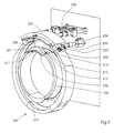
- FIG. 5 shows a schematic rear view of the cam box 200, as shown in FIG (Collective mode), the cam housing 207 is not shown.
- the couple Bearing 208 and the pair of springs 209 are visible.
- the present invention enables automatic switching from simple Operating mode to collective operating mode and vice versa.
Landscapes
- Folding Of Thin Sheet-Like Materials, Special Discharging Devices, And Others (AREA)
- Measuring Pulse, Heart Rate, Blood Pressure Or Blood Flow (AREA)
- Ultra Sonic Daignosis Equipment (AREA)
- Electrotherapy Devices (AREA)
Abstract
Description
- Fig. 1
- zeigt eine schematische Seitenansicht eines 3 zu 2-Falzapparats mit einem rotierenden Falzmesser aus dem Stand der Technik bei der einfachen Produktion; und
- Fig. 2
- zeigt eine schematische Seitenansicht eines 3 zu 2-Falzapparats mit einem rotierenden Falzmesser aus dem Stand der Technik bei der Sammelproduktion.
- Fig. 3
- eine schematische Frontansicht des Nockenkastens des erfindungsgemäßen Falzapparats im einfachen Betriebsmodus,
- Fig. 4
- eine schematische Frontansicht des Nockenkastens aus Fig. 3 im Sammelbetriebsmodus, und
- Fig. 5
- eine schematische Rückansicht des Nockenkastens aus Fig. 4.
- 1,2,3
- Nadel
- 10
- Falzapparat
- 11, 12, 13
- Nockenstößel
- 21, 22
- erhöhter Abschnitt
- 23
- nicht erhöhter Abschnitt
- 30
- Falzwalzen
- 102,104, 105, 106, 107,108
- Signatur
- 200
- Nockenkasten
- 201
- zweites bewegbares Nockensegment
- 202
- Nockenkonsole
- 203
- Paar Haltenadeln
- 204
- Paar erster Luftzylinder
- 205
- Paar Hebel
- 206
- zweites Paar Luftzylinder
- 207
- Nockensegmentgehäuse
- 208
- Paar Lager
- 209
- Paar Federn
- 210
- erster erhöhter Abschnitt
- 211
- erhöhter Abschnitt
- 212
- ausgeschnittener Abschnitt
- 213, 214
- gebogener Abschnitt
- 222
- unterer Abschnitt
- 230
- gebogener Abschnitt
- 240
- Löcher
- 250
- Paar Gelenkzapfen
Claims (18)
- Falzapparat mit
einer Nocke mit einem Nockenstößelpfad, mindestens einem Nockenstößel in dem Nockenstößelpfad und mindestens einer Haltevorrichtung zum Halten einer Kante einer Signatur, wobei die Haltevorrichtung von dem mindestens einem Nockenstößel betätigt wird,
dadurch gekennzeichnet, dass die Nocke ein bewegbares Segment mit einem ersten Betätigungsteil und
einen zweiten Betätigungsteil aufweist, welche wahlweise in den Nockenstößelpfad bewegbar sind. - Falzapparat nach Anspruch 1,
dadurch gekennzeichnet, dass der erste Betätigungsteil einen erhöhten Abschnitt (210, 211) umfasst, und der zweite Teil ein nicht erhöhter gebogener Abschnitt (213, 214) mit einem Kurvenradius ähnlich einem Hauptabschnitt des Nockenstößelpfads ist. - Falzapparat nach Anspruch 1 oder 2,
dadurch gekennzeichnet, dass die Nocke ein Nockenkasten (200) ist. - Falzapparat nach Anspruch 1,2 oder 3,
dadurch gekennzeichnet, dass der erste Betätigungsteil einen erhöhten Abschnitt (210, 211) und einen entsprechenden ausgeschnittenen Abschnitt (212) umfasst. - Falzapparat nach einem der vorhergehenden Ansprüche,
dadurch gekennzeichnet, dass die Nocke einen zweiten erhöhten Abschnitt (211) umfasst, der im Bezug auf den Nockenstößelpfad ortsfest ist. - Falzapparat nach einem der vorhergehenden Ansprüche,
dadurch gekennzeichnet, dass das bewegbare Segment axial entlang der Nockenkonsole (202) der Nocke verschiebbar ist. - Falzapparat nach einem der vorhergehenden Ansprüche,
dadurch gekennzeichnet, dass der Falzapparat des Weiteren ein Paar Lager (208) umfasst, das die Schlitze in der Nockenkonsole (202) passiert, um eine Bewegung des bewegbaren Segments im Bezug auf die Nockenkonsole (202) zu ermöglichen. - Falzapparat nach einem der vorhergehenden Ansprüche,
dadurch gekennzeichnet, dass der Falzapparat des Weiteren mindestens einen Luftzylinder (204) zum Bewegen des bewegbaren Segments umfasst. - Falzapparat nach einem der vorhergehenden Ansprüche,
dadurch gekennzeichnet, dass der Falzapparat des Weiteren mindestens eine Haltenadel (203) zum Arretieren des bewegbaren Segments in einer der beiden Positionen umfasst. - Falzapparat nach Anspruch 9,
dadurch gekennzeichnet, dass das bewegbare Segment mindestens zwei Löcher (240) zum Zusammenwirken mit einer der Haltenadeln (203) umfasst. - Falzapparat nach einem der vorhergehenden Ansprüche,
dadurch gekennzeichnet, dass der Falzapparat des Weiteren einen Luftzylinder (204) zum Schalten der mindestens einen Haltenadel (203) umfasst. - Falzapparat nach einem der vorhergehenden Ansprüche,
dadurch gekennzeichnet, dass der Falzapparat ein 3 zu 2-Falzapparat mit einem rotierenden Falzmesser ist. - Druckmaschine mit einem Falzapparat,
gekennzeichnet durch
einen Falzapparat gemäß einem der vorhergehenden Ansprüche. - Verfahren zum Umschalten eines Falzapparates vom einfachen Betriebsmodus in den Sammelbetriebsmodus, wobei der Falzapparat von einer Nocke betätigt wird,
gekennzeichnet durchBewegen eines bewegbaren Segments der Nocke, so dass ein erhöhter Abschnitt (210, 211) des bewegbaren Segments in dem Nockenstößelpfad der Nocke liegt, um einen einfachen Betriebsmodus des Falzapparates zum ermöglichen, undBewegen des bewegbaren Segments der Nocke, so dass ein nicht erhöhter Abschnitt des bewegbaren Segments in dem Nockenstößelpfad der Nocke liegt, um einen Sammelbetriebsmodus des Falzapparats zu ermöglichen. - Verfahren nach Anspruch 14,
dadurch gekennzeichnet, dass die Schritte des Bewegens unter Verwendung von Luftzylindern (204, 206) ausgeführt werden. - Verfahren nach Anspruch 14 oder 15,
dadurch gekennzeichnet, dass der Schritt des Arretierens des bewegbaren Segments im Sammelbetriebsmodus oder einfachen Betriebsmodus die Verwendung einer Haltenadel (203) umfasst. - Verfahren nach Anspruch 14, 15 oder 16,
dadurch gekennzeichnet, dass die Schritte des Bewegens durch eine axiale Schiebebewegung des bewegbaren Segments ausgeführt werden. - Verfahren zum Betreiben eines Falzapparats mit einem rotierenden Falzmesser
gekennzeichnet durch
die folgenden Verfahrensschritte:Bewegen eines Nockenstößels um einen Nockenstößelpfad einer Nocke;Loslassen und Halten der Vorderkanten von Signaturen auf dem Falzapparat mit einem rotierenden Falzmesser in Abhängigkeit von dem Nockenstößel, der sich auf dem Nockenstößelpfad bewegt; undBewegen eines bewegbaren Segments der Nocke durch eine Betätigungsvorrichtung, um den Nockenstößelpfad zu verändern und den Falzapparat mit einem rotierenden Messer vom einfachen Betriebsmodus auf Sammelbetriebsmodus umzuschalten.
Applications Claiming Priority (2)
| Application Number | Priority Date | Filing Date | Title |
|---|---|---|---|
| US728323 | 1985-04-29 | ||
| US09/728,323 US6547232B2 (en) | 2000-12-01 | 2000-12-01 | Device and method for switching between collect and straight modes on a folder |
Publications (3)
| Publication Number | Publication Date |
|---|---|
| EP1211213A2 true EP1211213A2 (de) | 2002-06-05 |
| EP1211213A3 EP1211213A3 (de) | 2003-09-17 |
| EP1211213B1 EP1211213B1 (de) | 2005-03-02 |
Family
ID=24926378
Family Applications (1)
| Application Number | Title | Priority Date | Filing Date |
|---|---|---|---|
| EP01126458A Expired - Lifetime EP1211213B1 (de) | 2000-12-01 | 2001-11-09 | Vorrichtung und Verfahren zum Umschalten zwischen Sammelbetriebsmodus und einfachem Betriebsmodus eines Falzapparats |
Country Status (5)
| Country | Link |
|---|---|
| US (1) | US6547232B2 (de) |
| EP (1) | EP1211213B1 (de) |
| JP (1) | JP2002173266A (de) |
| AT (1) | ATE289972T1 (de) |
| DE (2) | DE10155036A1 (de) |
Families Citing this family (5)
| Publication number | Priority date | Publication date | Assignee | Title |
|---|---|---|---|---|
| DE102004047492B4 (de) * | 2004-09-23 | 2006-07-20 | Jost-Werke Gmbh & Co. Kg | Verfahren zum Übertragen von elektrischer, pneumatischer oder hydraulischer Energie sowie ein Energieübertragungssystem |
| FR2905081B1 (fr) * | 2006-08-28 | 2010-04-30 | Goss Systemes Graphiques Nante | Plieuse a came masque retractable pour changement de mode de fonctionnement. |
| WO2009137488A1 (en) * | 2008-05-05 | 2009-11-12 | Goss International Americas, Inc. | Three-around broadsheet newspaper printing press and methods |
| WO2010059842A1 (en) * | 2008-11-21 | 2010-05-27 | Goss International Americas, Inc. | Variable cutoff alignment apparatus and method of aligning printing cylinders during a cutoff change |
| DE102013102728A1 (de) * | 2013-03-18 | 2014-09-18 | Manroland Web Systems Gmbh | Falzeinrichtung einer Druckmaschine und Verfahren zum Betreiben der Falzeinrichtung |
Family Cites Families (12)
| Publication number | Priority date | Publication date | Assignee | Title |
|---|---|---|---|---|
| US3038719A (en) * | 1959-01-22 | 1962-06-12 | Miehle Goss Dexter Inc | Cutting and folding mechanism |
| US3865361A (en) * | 1973-09-11 | 1975-02-11 | John C Motter Printing Press C | Folder cylinder |
| DE3828372C2 (de) * | 1988-08-20 | 1995-12-21 | Frankenthal Ag Albert | Falzapparat |
| DE4041613A1 (de) * | 1990-02-19 | 1991-08-22 | Frankenthal Ag Albert | Falzapparat |
| US5088708A (en) * | 1990-12-05 | 1992-02-18 | Rockwell International Corporation | Folding cylinder assembly having one piece cam |
| DE4117205A1 (de) * | 1991-05-27 | 1992-12-03 | Frankenthal Ag Albert | Falzapparat |
| FR2726259B1 (fr) * | 1994-10-27 | 1997-01-17 | Heidelberg Harris Sa | Dispositif de changement de mode d'un cylindre d'accumulation d'une plieuse |
| DE29502957U1 (de) * | 1995-02-22 | 1995-04-06 | MAN Roland Druckmaschinen AG, 63075 Offenbach | Zylinder in einem Falzwerk mit vertellbarem Durchmesser |
| EP0764604B1 (de) | 1995-09-19 | 2000-05-17 | Goss Graphic Systems, Inc. | Antriebsvorrichtung für eine Falzmaschine in einer Druckmaschine |
| US6093139A (en) | 1998-01-27 | 2000-07-25 | Heidelberger Druckmaschinen Ag | Folding apparatus for rotary printing presses |
| US6250622B1 (en) * | 1999-05-20 | 2001-06-26 | Heidelberger Druckmaschinen Aktiengesellschaft | Cylinder assembly for a folding apparatus of a rotary printing press |
| JP3038212B1 (ja) * | 1999-07-15 | 2000-05-08 | 株式会社東京機械製作所 | 折胴及び折畳装置における針動作タイミング調整装置 |
-
2000
- 2000-12-01 US US09/728,323 patent/US6547232B2/en not_active Expired - Fee Related
-
2001
- 2001-11-09 DE DE10155036A patent/DE10155036A1/de not_active Withdrawn
- 2001-11-09 DE DE50105463T patent/DE50105463D1/de not_active Expired - Lifetime
- 2001-11-09 AT AT01126458T patent/ATE289972T1/de not_active IP Right Cessation
- 2001-11-09 EP EP01126458A patent/EP1211213B1/de not_active Expired - Lifetime
- 2001-12-03 JP JP2001369142A patent/JP2002173266A/ja active Pending
Also Published As
| Publication number | Publication date |
|---|---|
| JP2002173266A (ja) | 2002-06-21 |
| DE10155036A1 (de) | 2002-08-01 |
| EP1211213A3 (de) | 2003-09-17 |
| DE50105463D1 (de) | 2005-04-07 |
| US20020066381A1 (en) | 2002-06-06 |
| EP1211213B1 (de) | 2005-03-02 |
| ATE289972T1 (de) | 2005-03-15 |
| US6547232B2 (en) | 2003-04-15 |
Similar Documents
| Publication | Publication Date | Title |
|---|---|---|
| EP0408912B1 (de) | Verfahren und Vorrichtung zum Herstellen von Papierstapeln | |
| EP0023630B1 (de) | Falzapparat an Rollen-Rotationsdruckmaschinen | |
| EP1925579B1 (de) | Schwertfalzmaschine mit vorgelagertem Taschenfalzwerk und Verfahren zum Falzen von Bogen aus flächigem Bedruckstoff | |
| EP0575787A1 (de) | Falzapparat zum Herstellen von gefalteten Exemplaren aus einer bedruckten Papierbahn | |
| EP0046261A1 (de) | Falzapparat | |
| DE4301093A1 (de) | ||
| DE3404170C2 (de) | Falzapparat an Rollenrotationsdruckmaschinen | |
| DE60111037T2 (de) | Kombination einer rotationsfalzmaschine mit einem falzklappenzylinder für eine druckmaschine | |
| DE4340858C2 (de) | Zylinder | |
| EP0938443B1 (de) | Falzapparat | |
| EP1473125B1 (de) | Vorrichtung zum Bewegen von Buchblöcken in einer Vorrichtung zum Beschneiden von Buchblöcken | |
| EP1211213B1 (de) | Vorrichtung und Verfahren zum Umschalten zwischen Sammelbetriebsmodus und einfachem Betriebsmodus eines Falzapparats | |
| DE69916596T2 (de) | Vorrichtung zur Einstellung der zeitlichen Steuerung der Punkturnadeln in einem Falzzylinder | |
| EP1116560A2 (de) | Schneidevorrichtung mit variabler Abschnittslänge | |
| DE69608386T2 (de) | Antriebsvorrichtung für eine Falzmaschine in einer Druckmaschine | |
| DE1276660B (de) | Vorrichtung zum Falten von Papierbogen od. dgl. | |
| EP1260325A1 (de) | Dreimesserschneidemaschine | |
| EP1106551A2 (de) | Vorrichtung und Verfahren zum Schneiden einer Bahn | |
| DE10211108A1 (de) | Falzapparat mit gruppenweise verstellbaren Falzklappen | |
| EP1156006B1 (de) | Trommelfalzapparat mit einem Falzmesserzylinder | |
| EP0015311A1 (de) | Vorrichtung zum Falten von Faltgutstücken | |
| EP0029528B1 (de) | Rollenrotationsdruckmaschine mit einer Bahnverbindungseinrichtung | |
| DE102007005009A1 (de) | Querperforationseinheit eines Falzapparats einer Druckmaschine sowie Verfahren zum Betreiben einer Querperforationseinheit eines Falzapparats | |
| DE102005017232B4 (de) | Sammelzylinder eines Falzapparats einer Druckmaschine | |
| EP2061714A1 (de) | Falzapparate mit einem falzmesserzylinder und einem falzklappenzylinder |
Legal Events
| Date | Code | Title | Description |
|---|---|---|---|
| PUAI | Public reference made under article 153(3) epc to a published international application that has entered the european phase |
Free format text: ORIGINAL CODE: 0009012 |
|
| AK | Designated contracting states |
Kind code of ref document: A2 Designated state(s): AT BE CH CY DE DK ES FI FR GB GR IE IT LI LU MC NL PT SE TR |
|
| AX | Request for extension of the european patent |
Free format text: AL;LT;LV;MK;RO;SI |
|
| PUAL | Search report despatched |
Free format text: ORIGINAL CODE: 0009013 |
|
| AK | Designated contracting states |
Kind code of ref document: A3 Designated state(s): AT BE CH CY DE DK ES FI FR GB GR IE IT LI LU MC NL PT SE TR |
|
| AX | Request for extension of the european patent |
Extension state: AL LT LV MK RO SI |
|
| RIC1 | Information provided on ipc code assigned before grant |
Ipc: 7B 65H 45/28 A Ipc: 7B 65H 45/16 B |
|
| 17P | Request for examination filed |
Effective date: 20030821 |
|
| 17Q | First examination report despatched |
Effective date: 20040223 |
|
| AKX | Designation fees paid |
Designated state(s): AT BE CH CY DE DK ES FI FR GB GR IE IT LI LU MC NL PT SE TR |
|
| GRAP | Despatch of communication of intention to grant a patent |
Free format text: ORIGINAL CODE: EPIDOSNIGR1 |
|
| RAP1 | Party data changed (applicant data changed or rights of an application transferred) |
Owner name: GOSS INTERNATIONAL AMERICAS, INC. |
|
| GRAS | Grant fee paid |
Free format text: ORIGINAL CODE: EPIDOSNIGR3 |
|
| GRAA | (expected) grant |
Free format text: ORIGINAL CODE: 0009210 |
|
| AK | Designated contracting states |
Kind code of ref document: B1 Designated state(s): AT BE CH CY DE DK ES FI FR GB GR IE IT LI LU MC NL PT SE TR |
|
| PG25 | Lapsed in a contracting state [announced via postgrant information from national office to epo] |
Ref country code: IT Free format text: LAPSE BECAUSE OF FAILURE TO SUBMIT A TRANSLATION OF THE DESCRIPTION OR TO PAY THE FEE WITHIN THE PRESCRIBED TIME-LIMIT;WARNING: LAPSES OF ITALIAN PATENTS WITH EFFECTIVE DATE BEFORE 2007 MAY HAVE OCCURRED AT ANY TIME BEFORE 2007. THE CORRECT EFFECTIVE DATE MAY BE DIFFERENT FROM THE ONE RECORDED. Effective date: 20050302 Ref country code: NL Free format text: LAPSE BECAUSE OF FAILURE TO SUBMIT A TRANSLATION OF THE DESCRIPTION OR TO PAY THE FEE WITHIN THE PRESCRIBED TIME-LIMIT Effective date: 20050302 Ref country code: TR Free format text: LAPSE BECAUSE OF FAILURE TO SUBMIT A TRANSLATION OF THE DESCRIPTION OR TO PAY THE FEE WITHIN THE PRESCRIBED TIME-LIMIT Effective date: 20050302 Ref country code: IE Free format text: LAPSE BECAUSE OF FAILURE TO SUBMIT A TRANSLATION OF THE DESCRIPTION OR TO PAY THE FEE WITHIN THE PRESCRIBED TIME-LIMIT Effective date: 20050302 Ref country code: FI Free format text: LAPSE BECAUSE OF FAILURE TO SUBMIT A TRANSLATION OF THE DESCRIPTION OR TO PAY THE FEE WITHIN THE PRESCRIBED TIME-LIMIT Effective date: 20050302 |
|
| REG | Reference to a national code |
Ref country code: GB Ref legal event code: FG4D Free format text: NOT ENGLISH |
|
| REG | Reference to a national code |
Ref country code: CH Ref legal event code: EP |
|
| REG | Reference to a national code |
Ref country code: IE Ref legal event code: FG4D Free format text: GERMAN |
|
| REF | Corresponds to: |
Ref document number: 50105463 Country of ref document: DE Date of ref document: 20050407 Kind code of ref document: P |
|
| PG25 | Lapsed in a contracting state [announced via postgrant information from national office to epo] |
Ref country code: DK Free format text: LAPSE BECAUSE OF FAILURE TO SUBMIT A TRANSLATION OF THE DESCRIPTION OR TO PAY THE FEE WITHIN THE PRESCRIBED TIME-LIMIT Effective date: 20050602 Ref country code: GR Free format text: LAPSE BECAUSE OF FAILURE TO SUBMIT A TRANSLATION OF THE DESCRIPTION OR TO PAY THE FEE WITHIN THE PRESCRIBED TIME-LIMIT Effective date: 20050602 |
|
| PG25 | Lapsed in a contracting state [announced via postgrant information from national office to epo] |
Ref country code: ES Free format text: LAPSE BECAUSE OF FAILURE TO SUBMIT A TRANSLATION OF THE DESCRIPTION OR TO PAY THE FEE WITHIN THE PRESCRIBED TIME-LIMIT Effective date: 20050613 |
|
| GBT | Gb: translation of ep patent filed (gb section 77(6)(a)/1977) |
Effective date: 20050614 |
|
| REG | Reference to a national code |
Ref country code: CH Ref legal event code: NV Representative=s name: KIRKER & CIE SA |
|
| PG25 | Lapsed in a contracting state [announced via postgrant information from national office to epo] |
Ref country code: PT Free format text: LAPSE BECAUSE OF FAILURE TO SUBMIT A TRANSLATION OF THE DESCRIPTION OR TO PAY THE FEE WITHIN THE PRESCRIBED TIME-LIMIT Effective date: 20050817 |
|
| NLV1 | Nl: lapsed or annulled due to failure to fulfill the requirements of art. 29p and 29m of the patents act | ||
| REG | Reference to a national code |
Ref country code: IE Ref legal event code: FD4D |
|
| PG25 | Lapsed in a contracting state [announced via postgrant information from national office to epo] |
Ref country code: CY Free format text: LAPSE BECAUSE OF FAILURE TO SUBMIT A TRANSLATION OF THE DESCRIPTION OR TO PAY THE FEE WITHIN THE PRESCRIBED TIME-LIMIT Effective date: 20051109 Ref country code: AT Free format text: LAPSE BECAUSE OF NON-PAYMENT OF DUE FEES Effective date: 20051109 |
|
| PG25 | Lapsed in a contracting state [announced via postgrant information from national office to epo] |
Ref country code: BE Free format text: LAPSE BECAUSE OF NON-PAYMENT OF DUE FEES Effective date: 20051130 Ref country code: MC Free format text: LAPSE BECAUSE OF NON-PAYMENT OF DUE FEES Effective date: 20051130 Ref country code: LU Free format text: LAPSE BECAUSE OF NON-PAYMENT OF DUE FEES Effective date: 20051130 |
|
| ET | Fr: translation filed | ||
| PLBE | No opposition filed within time limit |
Free format text: ORIGINAL CODE: 0009261 |
|
| STAA | Information on the status of an ep patent application or granted ep patent |
Free format text: STATUS: NO OPPOSITION FILED WITHIN TIME LIMIT |
|
| 26N | No opposition filed |
Effective date: 20051205 |
|
| BERE | Be: lapsed |
Owner name: GOSS INTERNATIONAL AMERICAS, INC. Effective date: 20051130 |
|
| PG25 | Lapsed in a contracting state [announced via postgrant information from national office to epo] |
Ref country code: SE Free format text: LAPSE BECAUSE OF FAILURE TO SUBMIT A TRANSLATION OF THE DESCRIPTION OR TO PAY THE FEE WITHIN THE PRESCRIBED TIME-LIMIT Effective date: 20050602 |
|
| PGFP | Annual fee paid to national office [announced via postgrant information from national office to epo] |
Ref country code: FR Payment date: 20101202 Year of fee payment: 10 |
|
| PGFP | Annual fee paid to national office [announced via postgrant information from national office to epo] |
Ref country code: DE Payment date: 20101126 Year of fee payment: 10 Ref country code: CH Payment date: 20101124 Year of fee payment: 10 |
|
| PGFP | Annual fee paid to national office [announced via postgrant information from national office to epo] |
Ref country code: GB Payment date: 20101124 Year of fee payment: 10 |
|
| REG | Reference to a national code |
Ref country code: CH Ref legal event code: PL |
|
| GBPC | Gb: european patent ceased through non-payment of renewal fee |
Effective date: 20111109 |
|
| PG25 | Lapsed in a contracting state [announced via postgrant information from national office to epo] |
Ref country code: CH Free format text: LAPSE BECAUSE OF NON-PAYMENT OF DUE FEES Effective date: 20111130 Ref country code: LI Free format text: LAPSE BECAUSE OF NON-PAYMENT OF DUE FEES Effective date: 20111130 |
|
| REG | Reference to a national code |
Ref country code: FR Ref legal event code: ST Effective date: 20120731 |
|
| REG | Reference to a national code |
Ref country code: DE Ref legal event code: R119 Ref document number: 50105463 Country of ref document: DE Effective date: 20120601 |
|
| PG25 | Lapsed in a contracting state [announced via postgrant information from national office to epo] |
Ref country code: GB Free format text: LAPSE BECAUSE OF NON-PAYMENT OF DUE FEES Effective date: 20111109 |
|
| PG25 | Lapsed in a contracting state [announced via postgrant information from national office to epo] |
Ref country code: FR Free format text: LAPSE BECAUSE OF NON-PAYMENT OF DUE FEES Effective date: 20111130 |
|
| PG25 | Lapsed in a contracting state [announced via postgrant information from national office to epo] |
Ref country code: DE Free format text: LAPSE BECAUSE OF NON-PAYMENT OF DUE FEES Effective date: 20120601 |