EP1211140A2 - Gehäuse für ein elektronisches Überwachungsgerät an Fahrzeugteilen - Google Patents
Gehäuse für ein elektronisches Überwachungsgerät an Fahrzeugteilen Download PDFInfo
- Publication number
- EP1211140A2 EP1211140A2 EP01128351A EP01128351A EP1211140A2 EP 1211140 A2 EP1211140 A2 EP 1211140A2 EP 01128351 A EP01128351 A EP 01128351A EP 01128351 A EP01128351 A EP 01128351A EP 1211140 A2 EP1211140 A2 EP 1211140A2
- Authority
- EP
- European Patent Office
- Prior art keywords
- base plate
- housing
- housing body
- housing according
- contact
- Prior art date
- Legal status (The legal status is an assumption and is not a legal conclusion. Google has not performed a legal analysis and makes no representation as to the accuracy of the status listed.)
- Granted
Links
- 238000012806 monitoring device Methods 0.000 title claims abstract description 8
- 239000002184 metal Substances 0.000 claims description 6
- 238000005476 soldering Methods 0.000 claims description 5
- 230000001681 protective effect Effects 0.000 claims description 3
- 239000011324 bead Substances 0.000 claims description 2
- 238000007765 extrusion coating Methods 0.000 claims 1
- 238000000465 moulding Methods 0.000 abstract description 2
- 229910000679 solder Inorganic materials 0.000 description 3
- 238000002347 injection Methods 0.000 description 1
- 239000007924 injection Substances 0.000 description 1
- 238000004519 manufacturing process Methods 0.000 description 1
- 230000035515 penetration Effects 0.000 description 1
Images

Classifications
-
- H—ELECTRICITY
- H05—ELECTRIC TECHNIQUES NOT OTHERWISE PROVIDED FOR
- H05K—PRINTED CIRCUITS; CASINGS OR CONSTRUCTIONAL DETAILS OF ELECTRIC APPARATUS; MANUFACTURE OF ASSEMBLAGES OF ELECTRICAL COMPONENTS
- H05K5/00—Casings, cabinets or drawers for electric apparatus
- H05K5/10—Casings, cabinets or drawers for electric apparatus comprising several parts forming a closed casing
- H05K5/15—Casings, cabinets or drawers for electric apparatus comprising several parts forming a closed casing assembled by resilient members
Definitions
- the invention relates to a housing for an electronic monitoring device on vehicle parts, in particular on a lead accumulator.
- housings for electronic monitoring devices on vehicle parts are made of metal or plastic.
- Metallic housing have a base plate with which the attachment to the vehicle part can.
- Plastic housings can be molded with for the purpose of attachment Tabs or flanges can be provided.
- the invention provides a housing for an electronic monitoring device provided that is inexpensive to manufacture in large series and meets all mechanical and electrical requirements.
- the Housing according to the invention has a supporting metallic base plate and a formed by overmolding the base plate, generally cuboid Housing body.
- the base plate projects with at least one side self-supporting fastening section out of the housing body.
- the housing is particularly suitable for accommodating an electronic charge status indicator for lead accumulators. Due to the cantilevered attachment section is a direct attachment to a suitably designed pole terminal possible. It pole terminals are known in which relatively thick electrical cables are connected towering stud bolts can be connected. If the attachment section with appropriate mounting holes, he can immediately be attached to the studs of the pole clamp. The fastening section then serves at the same time the electrical connection with the particularly positive Battery.
- the base plate is shared with one or more contact sheets punched out of a metal sheet. there are the base plate and the contact plates of an outer holding frame held together after the molding of the base plate on the outside the molded housing body is separated.
- the base plate and the contact plate are also with free punched, vertically bent solder nails connected to the Penetration into corresponding openings of a circuit board are determined on the the electronics of the device is set up.
- Each contact plate preferably has a contact tab that protrudes from the housing body and from one on Molded protective sleeve is surrounded.
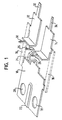
- FIG. 1 The structures shown in FIG. 1 are made from a metal sheet punched. This includes a base plate 10 and two contact plates 12, 14, with the base plate 10 on laterally projecting tabs by holding strips 16 are connected. These holding strips 16 form an outer holding frame which the base plate 10 is held in one plane with the contact plates 12, 14 to be inserted into an injection mold.
- the base plate 10 has two circular punched-out fastening openings 18, 20 and an embossed stiffening bead 22. Furthermore, with the base plate 10 a contact tab 24 is punched out, the free end of which is shaped as a soldering nail 26, which protrudes perpendicular to the base plate 10.
- the contact tab 24 consists of two oppositely oriented, U-shaped sections, which the soldering nail 26th hold in the desired raised position. The from the base plate 10 U-shaped section facing away forms a contact surface which is intended to to come into thermal contact with a temperature sensor element that a printed circuit board is built over it. Through the contact tab 24 is therefore a heat transfer from the positive pole of a lead accumulator over the Base plate 10 guaranteed on the temperature sensor element.
- each contact plate 12, 14 an inner end is angled vertically and carries a vertically protruding solder nail 28, 30.
- the solder nails 26, 28, 30 are Arranged at the same height and intended for this purpose in corresponding openings to penetrate a circuit board on which the electronic monitoring device is constructed, which is preferably a charge status indicator for a lead accumulator.
- Each contact plate 12, 14 also has one after contact tab 32, 34 projecting outside.
- Figure 2 shows a cuboid housing body 36 made of plastic, the by overmolding the base plate 10 and the contact plates 12, 14 with a suitable plastic mass has arisen.
- the holding strip 16 ( Figure 1) of the outer support frame are separated so that the electrical connection between base plate 10 and contact plates 12, 14 is eliminated.
- On a A self-supporting fastening section projects from the narrow side of the housing body 36 forming part 10a of the base plate 10 out.
- the contact lugs 32, 34 of the contact plates 12, 14 protrude from the narrow side. she are each formed by a protective sleeve 38, 40 formed on the housing body 36 surround. As such, the contact tabs 32, 34 can be pushed on immediately appropriate plug-in shoes suitable.
- a circuit board is designated in Figure 2, on which the electronics of the Device is built.
- the circuit board 42 has openings for the soldering nails 26, 28 and 30.
- the housing body 36 is provided with support structures 44 formed on the inside formed for the circuit board 42.
- the side of the cuboid housing opposite the base plate 10 36 is open and is closed by an attachable cover 46.
- the Cover 46 has latching openings 48 which are formed with latching lugs 50 on Housing body 36 cooperate to the attached cover 46 with the To keep housing body 36 connected.
Landscapes
- Engineering & Computer Science (AREA)
- Microelectronics & Electronic Packaging (AREA)
- Casings For Electric Apparatus (AREA)
- Coupling Device And Connection With Printed Circuit (AREA)
- Connection Of Batteries Or Terminals (AREA)
- Mounting Of Printed Circuit Boards And The Like (AREA)
- Fittings On The Vehicle Exterior For Carrying Loads, And Devices For Holding Or Mounting Articles (AREA)
- Secondary Cells (AREA)
Abstract
Description
- Figur 1 in Perspektivansicht eine Grundplatte und zwei Kontaktbleche, die gemeinsam aus einer Metallplatte ausgestanzt und durch einen äußeren Halterahmen verbunden sind; und
- Figur 2 eine Explosionsansicht eines elektronischen Überwachungsgeräts mit dem erfindungsgemäßen Gehäuse.
Claims (11)
- Gehäuse für ein elektronisches Überwachungsgerät an Fahrzeugteilen, insbesondere an einem Blei-Akkumulator, gekennzeichnet durch:wobei die Grundplatte auf wenigstens einer Seite aus dem Gehäusekörper mit einem freitragenden Befestigungsabschnitt herausragt.a) eine tragende metallische Grundplatte;b) einen durch Umspritzen der Grundplatte gebildeten allgemein quaderförmigen Gehäusekörper;
- Gehäuse nach Anspruch 1, dadurch gekennzeichnet, daß die Grundplatte aus einem Metallblech ausgestanzt ist.
- Gehäuse nach Anspruch 1 oder 2, dadurch gekennzeichnet, daß mit der Grundplatte wenigstens ein Kontaktblech aus dem Metallblech ausgestanzt ist, das wenigstens eine Kontaktfahne aufweist, die aus dem Gehäusekörper herausragt.
- Gehäuse nach Anspruch 3, dadurch gekennzeichnet, daß die Kontaktfahne von einer am Gehäusekörper angeformten Schutzhülse umgeben ist.
- Gehäuse nach einem der vorstehenden Ansprüche, dadurch gekennzeichnet, daß die Grundplatte wenigstens einen freigestanzten und senkrecht innerhalb des Gehäusekörpers hochgebogenen Lötnagel aufweist.
- Gehäuse nach einem der vorstehenden Ansprüche 3 bis 5, dadurch gekennzeichnet, daß die Kontaktplatte wenigstens einen freigestanzten und senkrecht innerhalb des Gehäusekörpers hochgebogenen Lötnagel aufweist.
- Gehäuse nach einem der vorstehenden Ansprüche, dadurch gekennzeichnet, daß der Gehäusekörper innenseitig angeformte Stützstrukturen für eine Leiterplatte aufweist.
- Gehäuse nach einem der vorstehenden Ansprüche, dadurch gekennzeichnet, daß der Gehäusekörper gegenüber der Grundplatte offen und durch einen aufgesetzten Deckel verschließbar ist.
- Gehäuse nach einem der vorstehenden Ansprüche, dadurch gekennzeichnet, daß der Befestigungsabschnitt der Grundplatte wenigstens eine geprägte Versteifungssicke aufweist.
- Gehäuse nach einem der vorstehenden Ansprüche, dadurch gekennzeichnet, daß der Befestigungsabschnitt wenigstens ein Befestigungsloch für den Durchgang eines Schraubbolzens aufweist, der an einer Polklemme befestigt ist.
- Gehäuse nach einem der vorstehenden Ansprüche, dadurch gekennzeichnet, daß die Grundplatte eine hochgebogene Kontaktfahne aufweist, die eine Anlagefläche für ein auf einer Leiterplatte aufgebautes Temperatur-Sensorelement bildet.
Applications Claiming Priority (2)
| Application Number | Priority Date | Filing Date | Title |
|---|---|---|---|
| DE20020392U DE20020392U1 (de) | 2000-12-01 | 2000-12-01 | Gehäuse für ein elektronisches Überwachungsgerät an Fahrzeugteilen |
| DE20020392U | 2000-12-01 |
Publications (3)
| Publication Number | Publication Date |
|---|---|
| EP1211140A2 true EP1211140A2 (de) | 2002-06-05 |
| EP1211140A3 EP1211140A3 (de) | 2003-11-12 |
| EP1211140B1 EP1211140B1 (de) | 2005-09-14 |
Family
ID=7949528
Family Applications (1)
| Application Number | Title | Priority Date | Filing Date |
|---|---|---|---|
| EP01128351A Expired - Lifetime EP1211140B1 (de) | 2000-12-01 | 2001-11-30 | Gehäuse für ein elektronisches Überwachungsgerät an Fahrzeugteilen |
Country Status (4)
| Country | Link |
|---|---|
| US (1) | US6850412B2 (de) |
| EP (1) | EP1211140B1 (de) |
| JP (1) | JP2002216859A (de) |
| DE (2) | DE20020392U1 (de) |
Cited By (2)
| Publication number | Priority date | Publication date | Assignee | Title |
|---|---|---|---|---|
| EP1640495A1 (de) * | 2004-09-20 | 2006-03-29 | Samsung Electronics Co., Ltd. | Verriegelungsvorrichtung und Trockner mit einer solchen Vorrichtung |
| DE102011009156A1 (de) * | 2011-01-22 | 2012-07-26 | Conti Temic Microelectronic Gmbh | Sensor Baugruppe |
Families Citing this family (12)
| Publication number | Priority date | Publication date | Assignee | Title |
|---|---|---|---|---|
| DE10134380B4 (de) * | 2001-07-14 | 2020-11-12 | HELLA GmbH & Co. KGaA | Gehäuse mit darin untergebrachter elektrischer Schaltung |
| DE10352854B4 (de) * | 2003-05-12 | 2020-02-13 | Continental Teves Ag & Co. Ohg | Befestigungsmittel für einen Sensor oder ein Sensorgehäuse |
| WO2004099722A2 (de) * | 2003-05-12 | 2004-11-18 | Continental Teves Ag & Co. Ohg | Befestigungsmittel für einen sensor oder ein sensorgehäuse |
| JP4786159B2 (ja) * | 2004-09-22 | 2011-10-05 | 日産自動車株式会社 | 電池収納容器及びその組立方法 |
| US7903430B2 (en) * | 2008-05-17 | 2011-03-08 | Kevin Yang | Recessed light ballast mount |
| US8096825B2 (en) * | 2009-03-25 | 2012-01-17 | Belkin International Inc. | Electrical coupler system and method for manufacture thereof |
| FR2953287B1 (fr) * | 2009-11-27 | 2017-07-21 | Mc Aci | Dispositif de mesure de grandeurs parietales |
| JP5766450B2 (ja) * | 2011-01-28 | 2015-08-19 | 矢崎総業株式会社 | 端子取付構造及び電子機器 |
| US9948049B2 (en) * | 2016-04-13 | 2018-04-17 | Paccar Inc | Starter post relocation assembly |
| CN106224337B (zh) * | 2016-07-29 | 2019-04-12 | 海南金盘电气有限公司 | 一种板件连接用卡弹片 |
| CN107819215B (zh) * | 2016-09-14 | 2024-04-09 | 泰科电子(上海)有限公司 | 连接器 |
| CN207052813U (zh) * | 2017-05-12 | 2018-02-27 | 泰科电子(上海)有限公司 | 插座壳体组件及插座 |
Family Cites Families (15)
| Publication number | Priority date | Publication date | Assignee | Title |
|---|---|---|---|---|
| US4518982A (en) * | 1981-02-27 | 1985-05-21 | Motorola, Inc. | High current package with multi-level leads |
| FR2503932A1 (fr) * | 1981-04-08 | 1982-10-15 | Thomson Csf | Boitiers a cosses plates pour composants semi-conducteurs de moyenne puissance et procede de fabrication |
| US4626962A (en) * | 1985-05-30 | 1986-12-02 | Motorola, Inc. | Circuit board assembly with built in wire gripper |
| US4782240A (en) * | 1986-06-26 | 1988-11-01 | Davidson Samuel L | Safety battery connector |
| US4924152A (en) * | 1988-06-13 | 1990-05-08 | Jon Flickinger | Thermoplastic ballast housing in a novel three-dimensional printed circuit board |
| DE8816054U1 (de) | 1988-12-24 | 1989-08-17 | Dynamit Nobel Ag, 5210 Troisdorf | Elektrisches Gerät |
| DE4313429A1 (de) * | 1993-04-27 | 1994-11-03 | Bosch Gmbh Robert | Elektrisches Gerät, insbesondere Schalt- und Steuergerät für Kraftfahrzeuge |
| DE4329083A1 (de) | 1993-08-30 | 1995-03-02 | Telefunken Microelectron | Baugruppe zur Aufnahme elektronischer Bauelemente |
| DE4437664A1 (de) | 1994-10-21 | 1996-04-25 | Bosch Gmbh Robert | Elektrisches Gerät und Verfahren zu dessen Herstellung |
| DE29506697U1 (de) | 1994-11-22 | 1995-07-06 | Doduco GmbH + Co Dr. Eugen Dürrwächter, 75181 Pforzheim | Aus Kunststoff gespritztes Gehäuseteil mit starren, metallischen, eingespritzten Zuleitungen |
| DE9420980U1 (de) | 1994-11-25 | 1995-02-23 | AMI DODUCO GmbH, 75181 Pforzheim | Zum Aufnehmen von elektronischen und/oder mikromechanischen Bauteilen bestimmtes Gehäuse aus einem Hartkunststoff, ins welches Leiterbahnen hineinführen |
| DE19709243C1 (de) * | 1997-03-06 | 1998-06-10 | Siemens Ag | Steuergerät für ein Kraftfahrzeug |
| US5872332A (en) * | 1997-06-27 | 1999-02-16 | Delco Electronics Corp. | Molded housing with EMI shield |
| DE19834740C2 (de) | 1998-08-01 | 2003-03-13 | Iq Battery Res & Dev Gmbh | Kraftfahrzeugbatterie mit integrierter Überwachungsvorrichtung und Verfahren zur Überwachung einer Kraftfahrzeugbatterie |
| US6347958B1 (en) * | 2000-09-18 | 2002-02-19 | Real Power Cap Company | Connecting device to vehicle battery terminals |
-
2000
- 2000-12-01 DE DE20020392U patent/DE20020392U1/de not_active Expired - Lifetime
-
2001
- 2001-11-27 JP JP2001360289A patent/JP2002216859A/ja active Pending
- 2001-11-30 DE DE50107413T patent/DE50107413D1/de not_active Expired - Lifetime
- 2001-11-30 EP EP01128351A patent/EP1211140B1/de not_active Expired - Lifetime
- 2001-11-30 US US09/998,105 patent/US6850412B2/en not_active Expired - Lifetime
Non-Patent Citations (1)
| Title |
|---|
| None |
Cited By (3)
| Publication number | Priority date | Publication date | Assignee | Title |
|---|---|---|---|---|
| EP1640495A1 (de) * | 2004-09-20 | 2006-03-29 | Samsung Electronics Co., Ltd. | Verriegelungsvorrichtung und Trockner mit einer solchen Vorrichtung |
| DE102011009156A1 (de) * | 2011-01-22 | 2012-07-26 | Conti Temic Microelectronic Gmbh | Sensor Baugruppe |
| US9212936B2 (en) | 2011-01-22 | 2015-12-15 | Conti Temic Microelectronic Gmbh | Sensor assembly |
Also Published As
| Publication number | Publication date |
|---|---|
| DE20020392U1 (de) | 2001-04-26 |
| JP2002216859A (ja) | 2002-08-02 |
| US20020088275A1 (en) | 2002-07-11 |
| DE50107413D1 (de) | 2005-10-20 |
| US6850412B2 (en) | 2005-02-01 |
| EP1211140A3 (de) | 2003-11-12 |
| EP1211140B1 (de) | 2005-09-14 |
Similar Documents
| Publication | Publication Date | Title |
|---|---|---|
| EP1145610B1 (de) | Elektronisches steuergerät | |
| DE69614267T2 (de) | Batterie verbinder | |
| DE4215041C3 (de) | Elektronisches Steuergerät | |
| EP1211140B1 (de) | Gehäuse für ein elektronisches Überwachungsgerät an Fahrzeugteilen | |
| EP0446323B1 (de) | Gehäuse für eine elektronische schaltung | |
| DE19822511B4 (de) | Auf einer Oberfläche befestigbare elektronische Bauelemente | |
| DE102006018716A1 (de) | Anordnung zur Kontaktierung von Leistungshalbleitern an einer Kühlfläche | |
| DE19632820A1 (de) | Verteilerplatte für elektrische Anschlüsse | |
| DE10304889A1 (de) | Elektronikleiterplattengehäuse und Verfahren zur Herstellung einer Elektronikschaltungseinheit | |
| DE3345435C2 (de) | Elektrischer Steckverbinder, insbesondere Miniatursteckverbinder | |
| DE102009018426A1 (de) | Leiterplatten-Halteaufbau und Antennenvorrichtung | |
| DE3841893A1 (de) | Lastschaltmodul fuer kraftfahrzeuge | |
| DE102005047479A1 (de) | Aufbau zum Verbinden eines Drahtes mit einer Elementaufnahmeeinheit | |
| DE19731411A1 (de) | Haltevorrichtung für elektrische Lüfter, insbesondere Kleinstlüfter | |
| DE10308612B3 (de) | Durch eine Trennwand führende elektrische Verbindung | |
| DE4313429A1 (de) | Elektrisches Gerät, insbesondere Schalt- und Steuergerät für Kraftfahrzeuge | |
| DE102009054767A1 (de) | Abschlusselement für ein Gehäuse | |
| DE2752847A1 (de) | Gehaeuse mit einem darin angeordneten elektrischen bauelement | |
| DE2539379B2 (de) | Vorrichtung zum Anschließen und Haltern eines Transistors an eine gedruckte Schaltung | |
| DE202010000903U1 (de) | Vorrichtung zur Zugentlastung und Gehäusewand-Durchführung von Litzen und Encoder | |
| DE102019134369B4 (de) | Leadframe für Drahtbauteile mit Kulissenstruktur | |
| DE102005026233B4 (de) | Elektrisches Leistungsmodul | |
| DE10013116A1 (de) | Vorrichtung zur lagerichtigen Befestigung einer Leiterplatte | |
| EP1037474B1 (de) | Elektronisches Gerät, insbesondere Fermeldevermittlungsanlage | |
| DE9215676U1 (de) | Innerhalb eines Kommunikationsendgerätes angeordneter Tonrufwandler |
Legal Events
| Date | Code | Title | Description |
|---|---|---|---|
| PUAI | Public reference made under article 153(3) epc to a published international application that has entered the european phase |
Free format text: ORIGINAL CODE: 0009012 |
|
| AK | Designated contracting states |
Kind code of ref document: A2 Designated state(s): AT BE CH CY DE DK ES FI FR GB GR IE IT LI LU MC NL PT SE TR |
|
| AX | Request for extension of the european patent |
Free format text: AL;LT;LV;MK;RO;SI |
|
| PUAL | Search report despatched |
Free format text: ORIGINAL CODE: 0009013 |
|
| AK | Designated contracting states |
Kind code of ref document: A3 Designated state(s): AT BE CH CY DE DK ES FI FR GB GR IE IT LI LU MC NL PT SE TR |
|
| AX | Request for extension of the european patent |
Extension state: AL LT LV MK RO SI |
|
| 17P | Request for examination filed |
Effective date: 20040309 |
|
| AKX | Designation fees paid |
Designated state(s): DE FR GB |
|
| GRAP | Despatch of communication of intention to grant a patent |
Free format text: ORIGINAL CODE: EPIDOSNIGR1 |
|
| GRAS | Grant fee paid |
Free format text: ORIGINAL CODE: EPIDOSNIGR3 |
|
| GRAA | (expected) grant |
Free format text: ORIGINAL CODE: 0009210 |
|
| AK | Designated contracting states |
Kind code of ref document: B1 Designated state(s): DE FR GB |
|
| RBV | Designated contracting states (corrected) |
Designated state(s): DE FR GB |
|
| REG | Reference to a national code |
Ref country code: GB Ref legal event code: FG4D Free format text: NOT ENGLISH |
|
| REF | Corresponds to: |
Ref document number: 50107413 Country of ref document: DE Date of ref document: 20051020 Kind code of ref document: P |
|
| GBT | Gb: translation of ep patent filed (gb section 77(6)(a)/1977) |
Effective date: 20051108 |
|
| ET | Fr: translation filed | ||
| PLBE | No opposition filed within time limit |
Free format text: ORIGINAL CODE: 0009261 |
|
| STAA | Information on the status of an ep patent application or granted ep patent |
Free format text: STATUS: NO OPPOSITION FILED WITHIN TIME LIMIT |
|
| 26N | No opposition filed |
Effective date: 20060615 |
|
| PGFP | Annual fee paid to national office [announced via postgrant information from national office to epo] |
Ref country code: FR Payment date: 20091123 Year of fee payment: 9 Ref country code: GB Payment date: 20091125 Year of fee payment: 9 |
|
| GBPC | Gb: european patent ceased through non-payment of renewal fee |
Effective date: 20101130 |
|
| REG | Reference to a national code |
Ref country code: FR Ref legal event code: ST Effective date: 20110801 |
|
| PG25 | Lapsed in a contracting state [announced via postgrant information from national office to epo] |
Ref country code: FR Free format text: LAPSE BECAUSE OF NON-PAYMENT OF DUE FEES Effective date: 20101130 |
|
| PG25 | Lapsed in a contracting state [announced via postgrant information from national office to epo] |
Ref country code: GB Free format text: LAPSE BECAUSE OF NON-PAYMENT OF DUE FEES Effective date: 20101130 |
|
| PGFP | Annual fee paid to national office [announced via postgrant information from national office to epo] |
Ref country code: DE Payment date: 20151127 Year of fee payment: 15 |
|
| REG | Reference to a national code |
Ref country code: DE Ref legal event code: R119 Ref document number: 50107413 Country of ref document: DE |
|
| PG25 | Lapsed in a contracting state [announced via postgrant information from national office to epo] |
Ref country code: DE Free format text: LAPSE BECAUSE OF NON-PAYMENT OF DUE FEES Effective date: 20170601 |