EP1211059A2 - Hydraulische Steuerung für eine hydraulisch betätigbare Kupplungsbremskombination insbesondere an der Exzenterwelle einer mechanischen Presse - Google Patents
Hydraulische Steuerung für eine hydraulisch betätigbare Kupplungsbremskombination insbesondere an der Exzenterwelle einer mechanischen Presse Download PDFInfo
- Publication number
- EP1211059A2 EP1211059A2 EP01127201A EP01127201A EP1211059A2 EP 1211059 A2 EP1211059 A2 EP 1211059A2 EP 01127201 A EP01127201 A EP 01127201A EP 01127201 A EP01127201 A EP 01127201A EP 1211059 A2 EP1211059 A2 EP 1211059A2
- Authority
- EP
- European Patent Office
- Prior art keywords
- pressure
- valve
- control
- hydraulic
- control valve
- Prior art date
- Legal status (The legal status is an assumption and is not a legal conclusion. Google has not performed a legal analysis and makes no representation as to the accuracy of the status listed.)
- Granted
Links
Images

Classifications
-
- B—PERFORMING OPERATIONS; TRANSPORTING
- B30—PRESSES
- B30B—PRESSES IN GENERAL
- B30B15/00—Details of, or accessories for, presses; Auxiliary measures in connection with pressing
- B30B15/14—Control arrangements for mechanically-driven presses
- B30B15/142—Control arrangements for mechanically-driven presses controlling the brake or the clutch
-
- B—PERFORMING OPERATIONS; TRANSPORTING
- B30—PRESSES
- B30B—PRESSES IN GENERAL
- B30B15/00—Details of, or accessories for, presses; Auxiliary measures in connection with pressing
- B30B15/10—Brakes specially adapted for presses
Definitions
- the invention is based on a hydraulic control for actuation a clutch brake combination especially the eccentric shaft of a mechanical Press is provided and the the features from the preamble of Claim 1 has.
- Such a hydraulic control is known from WO 00/02720. At this hydraulic control will primarily be a larger amount Pressure fluid is required if the hydraulic cylinder releases the brake and Closing the clutch moves and when the high clutch pressure builds up and the pressure medium is compressed. During the rest of a press cycle little or no pressure fluid is required.
- a hydraulic accumulator belongs to the pressure medium source, the within the cycle time in which the hydraulic cylinder has little pressure medium is needed, is charged by the hydraulic pump and then when a lot of pressure medium is needed, releases pressure medium.
- the inlet connection of a safety valve arrangement is which, for example, monitor two switching positions
- Directional control valves exist in a flow path leading from the pressure medium source the hydraulic cylinder can be built.
- the pressure control valve is an electrically pilot operated pressure control valve, the control piston of which is on the one hand by a pressure set by the electric pilot valve and is controlled by the pressure at the control connection.
- Pressure valves generally tend to swing. This tendency can only be avoided by appropriate damping can be avoided. But this makes the time to build one Pressure relatively long. The control quality is relatively low. In this respect is through a pressure control valve does not always meet the requirements.
- the aim of the invention is therefore a hydraulic control with the features evolve from the preamble of claim 1 so that it is a has high dynamics and thus short pressure build-up and pressure reduction times and a high control quality enables.
- a control according to the invention for a hydraulically actuatable clutch / brake combination is by means of the proportional directional valve, the electrical Pressure sensor and the control electronics an electro-hydraulic pressure control circuit built up.
- Such a control loop is distinguished from a hydromechanical one working pressure control valve by a higher dynamic and thus by shorter pressure change times and a higher control quality, a lower temperature and viscosity dependency, lower overshoot and lower adjustable pressure, which can go down to atmospheric pressure.
- a valve position of the control valve is particularly preferred can be monitored in terms of its use as a press safety valve. This is based on the rule that a pressure medium supply to the Only then can the hydraulic cylinder release the brake and engage the clutch may be if two directional control valves are working properly. For the cyclical Control of the correct function are the two directional control valves switching position monitoring. In a training according to claim 2 is now in addition to the control valve, there is only one additional switch position monitored Directional control valve necessary to comply with the regulation.
- control electronics are advantageously and the pressure sensor integrated into the control valve.
- the control valve is between the Safety valve assembly and the hydraulic cylinder, so that the in the hydraulic cylinder prevailing working pressure directly at that with the hydraulic cylinder connected working connection of the control valve can be tapped.
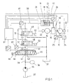
- the ram 10 of a press can be seen is connected to an eccentric shaft 12 via a coupling rod 11.
- a clutch-brake combination 13 from an electric motor 14 a drive shaft 15 are driven with a flywheel or braked become.
- Such clutch-brake combinations are general, for example known from DE-PS 1 207 725 or US-A 3,200,917, so that there is a further description is unnecessary. If no external force is applied, then by a spring assembly 16 released the clutch and the brake is effective. against the The spring arrangement can hydraulically release the brake and engage the clutch become.
- a single-acting hydraulic cylinder 18, the interior of which serves by a piston 19, to which a piston rod 17 is attached, in a fully cylindrical, pressure chamber 20 on the piston rod side and into a ring-cylindrical one piston-side receiving space 21 for the trained as a helical compression spring Spring arrangement 15 is divided.
- the pressure chamber 20 is relieved of pressure Brake with a determined by the bias of the helical compression spring 15 Force operated. If the pressure in the pressure chamber 20 rises, it initially decreases the braking force until finally the pressure one of the preload Helical compression spring assumes 15 equivalent value. Then the piston begins 19 and the piston rod 17 to move. The brake is released.
- eccentric shaft is a rotary encoder or a speed sensor 22 and with a rotary encoder or a speed sensor 23 is coupled to the drive shaft.
- An acceleration sensor is used to detect the states of the press ram 10 24 and / or a displacement sensor 25.
- a further displacement sensor 26 is provided, with which the position of the piston rod 17 can be detected.
- the hydraulic cylinder 18 is supplied with pressure medium from a pressure medium source, essentially a hydraulic pump 35 and a hydraulic accumulator 36 includes.
- the hydraulic pump 35 with a constant displacement is operated by an electric motor driven and sucks from a tank 37 per unit of time a relative small amount of pressure medium, which it delivers into a pressure line 38, to which also the hydraulic accumulator 36 is connected.
- the feeding of pressure medium into the pressure chamber 20 and the outflow of Pressure medium from the pressure chamber is shown in both exemplary embodiments by an electrically proportionally adjustable directional valve and at least one controlled another electrically switchable directional valve.
- a proportional directional valve 40 with one with the pressure line 38 connected pressure port 41, one connected to the tank 37 Tank connection 42 and with a consumer connection 43 available.
- the directional valve 40 is from a spring-centered center position with a negative overlap of the three connections mentioned, by controlling an electromagnet 44 or an electromagnet 45 continuously in opposite directions adjustable, with an opening cross-section when adjusted in one direction between the pressure connection and the work connection and with an adjustment in the opposite direction an opening cross-section between the Work connection and the tank connection is continuously increased.
- the connection the working connection to the other connection is already completely closed after a short distance.
- the way of the control piston of the directional valve 40 is detected by a displacement sensor 46.
- two 4/2-way switching valves 48 and 49 are inserted as safety valves, which each have a tank connection connected to the tank 37 and has a first consumer connection which is connected to a pressure chamber 20 of the Hydraulic cylinder 18 leading hydraulic line 50 is connected.
- Both valves 48 and 49 have a pressure connection, the pressure connection of the valve 48 with the consumer connection of the directional valve 40 and the pressure connection of the valve 49 is connected to a second consumer connection of the valve 48.
- On second consumer connection of the valve 49 is like its first consumer connection placed on the hydraulic line 50.
- the two valves 48 and 49 take a rest position under the action of a spring 51 one in which each connects the hydraulic line 50 to the tank 37.
- the other two connections (pressure connection and second consumer connection) each directional control valve 48 and 49 are shut off in the rest position of these valves.
- both directional control valves 48 and 49 are in their working position, brought into this by energization of one electromagnet 52 each , there are two further connections of the directional valve 48 and the other connections of the directional valve that are in series 49 a connection between the pressure chamber 20 and the consumer connection 43 of the directional valve 40.
- the pressure chamber 20 of the hydraulic cylinder 18 relieved of pressure.
- Each of the two valves 48 and 49 is with one Switch position transmitter 53 equipped, which emits a signal when a valve switches. If such a signal is omitted, although the device is to be switched over, the Plant shut down.
- a pressure transducer 60 is connected to the hydraulic line 50, of which the pressure in the pressure chamber 20 of the hydraulic cylinder 18 can be detected.
- the load cell 60 can also be connected directly to the consumer connection 43 of the Directional control valve 40 sit, since there at least when valves 48 and 49 are switched there is approximately the same pressure as in line 50.
- the electrical output signal the load cell 60 and the sensors 22, 23, 24, 25 and 26 are given to control electronics 61, of which via an amplifier Electromagnets 44 and 45 of the directional valve 40 can be controlled.
- the control electronics 61 enables in conjunction with the rotation angle or speed sensors 22 and 23 the eccentric shaft 12 and on the drive shaft 15 a further control of the coupling process.
- a slip control for example is conceivable Switching time minimization or wear optimization. It is also conceivable, for example an acceleration control during the coupling or braking process with the help of sensors 24 and 25.
- the second safety valve is due to the continuously adjustable directional valve 70 realized that, like the directional control valve 40 from FIG. 1, a pressure connection 41, a tank connection 42 directly connected to the tank 37 and two with the line 50 has connected consumer connections 43.
- the directional valve 70 is now directly upstream of the pressure chamber 20. Of course it would even a single consumer connection connected to line 50 is sufficient.
- the load cell 60 which is directly in a consumer connection 43rd taps the pressure, and the control electronics 61.
- the position of the control piston the directional control valve 70 can be detected by a displacement sensor 46. Also monitored a switch position transmitter 53, the directional valve 70.
- the directional control valve 70 assumes an end position under the action of a spring 71, in which the line 50 and thus the pressure chamber 20 of the hydraulic cylinder 18 via a Relieved consumer port 43 and the tank port 42 to the tank 37 are.
- the directional valve 70 can be moved from the end position by an electromagnet 45 out continuously in one direction, the opening cross-section is made smaller and smaller between the two connections 42 and 43, before after a phase of negative overlap between the connections the tank connection is closed, an opening cross-section between the Pressure port 41 and a consumer port 43 opened more and more becomes.
- the safety valve 48 has a pressure connection connected to the pressure line 38, a tank connection connected to the tank 37, one to the hydraulic line 50 connected first consumer connection and one with the pressure connection 41 of the directional control valve 70 connected second consumer connection and assumes a rest position under the action of a spring 51, in which the first Consumer connection with the tank connection, that is, the hydraulic line 50 with the Tank 37 is connected.
- the other two connections (pressure connection and second consumer connection) of the directional control valve 48 are blocked in the rest position.
- the pressure connection and the second consumer connection connected and the other two connections shut off. This relieves the pressure on each of the two directional valves 48 and 70 the pressure chamber 20 alone to the tank. So both have to Directional control valves have been brought out of their rest position so that an inflow of Pressure medium to the pressure chamber 20 is possible.
Landscapes
- Engineering & Computer Science (AREA)
- Mechanical Engineering (AREA)
- Hydraulic Clutches, Magnetic Clutches, Fluid Clutches, And Fluid Joints (AREA)
- Control Of Presses (AREA)
Abstract
Description
- Figur 1
- ein erstes Ausführungsbeispiel, bei dem das Proportional-Wegeventil zwischen der Druckmittelquelle und zwei Sicherheitsventilen angeordnet ist und
- Figur 2
- das zweites Ausführungsbeispiel, bei dem das Proportional-Wegeventil auch als Sicherheitsventil benutzt wird.
Claims (6)
- Hydraulische Steuerung für eine hydraulisch betätigbare Kupplungsbremskombination (13) insbesondere an der Exzenterwelle (12) einer mechanischen Presse mit einer eine Hydropumpe (35) und bevorzugt auch einen Hydrospeicher (36) aufweisenden Druckmittelquelle zur Versorgung eines die Kupplung und/oder die Bremse betätigenden Hydrozylinders (18) mit Druckmittel, mit einer Sicherheitsventilanordnung (48, 49), die einen Druckanschluß aufweist, über den ein Strömungspfad von der Druckmittelquelle (35, 36) zum Hydrozylinder (18) führt,
und mit einem proportional verstellbaren Regelventil (40, 70), mit dem der Druck einstellbar ist, von dem der Hydrozylinder (18) beaufschlagt ist,
dadurch gekennzeichnet, daß ein elektrischer Drucksensor (60) vorhanden ist, von dem der den Hydrozylinder (18) beaufschlagende Druck erfaßbar ist,
daß eine Regelelektronik (61) vorhanden ist, dem ein dem erfaßten Druck entsprechendes elektrisches Signal des Drucksensors (60) zugeführt wird
und daß das Regelventil (40, 70) ein elektrisch ansteuerbares Proportional-Wegeventil ist, das von der Regelelektronik (61) entsprechend dem erfaßten Ist-Druck und dem gewünschten Soll-Druck angesteuert wird. - Hydraulische Steuerung nach Anspruch 1, dadurch gekennzeichnet, daß eine Ventilstellung des Regelventils (70) im Sinne von dessen Verwendung als Sicherheitsventil überwacht wird.
- Hydraulische Steuerung nach Anspruch 2, dadurch gekennzeichnet, daß das Regelventil (70) mit einem Wegaufnehmer (46) für die Ventilposition ausgestattet ist und daß die Überwachung der Ventilstellung mittels Auswertung des Ausgangssignals des Wegaufnehmers (46) geschieht.
- Hydraulische Steuerung nach Anspruch 2, dadurch gekennzeichnet, daß das Regelventil (70) mit einem Ventilstellungsgeber (53) ausgestattet ist, mit dem die bestimmte Ventilstellung erfaßbar ist.
- Hydraulische Steuerung nach einem vorhergehenden Anspruch, dadurch gekennzeichnet, daß die Regelelektronik (61) und das Regelventil (70) zu einer Baueinheit zusammengefaßt sind.
- Hydraulische Steuerung nach einem vorhergehenden Anspruch, dadurch gekennzeichnet, daß der Drucksensor (60) und das Regelventil (70) zu einer Baueinheit zusammengefaßt sind.
Applications Claiming Priority (4)
| Application Number | Priority Date | Filing Date | Title |
|---|---|---|---|
| DE10060083 | 2000-12-02 | ||
| DE10060083 | 2000-12-02 | ||
| DE10062229 | 2000-12-13 | ||
| DE10062229A DE10062229A1 (de) | 2000-12-02 | 2000-12-13 | Hydraulische Steuerung für eine hydraulisch betätigbare Kupplungsbremskombination insbesondere an der Exzenterwelle einer mechanischen Presse |
Publications (3)
| Publication Number | Publication Date |
|---|---|
| EP1211059A2 true EP1211059A2 (de) | 2002-06-05 |
| EP1211059A3 EP1211059A3 (de) | 2003-04-16 |
| EP1211059B1 EP1211059B1 (de) | 2006-08-16 |
Family
ID=26007867
Family Applications (1)
| Application Number | Title | Priority Date | Filing Date |
|---|---|---|---|
| EP20010127201 Expired - Lifetime EP1211059B1 (de) | 2000-12-02 | 2001-11-16 | Hydraulische Steuerung für eine hydraulisch betätigbare Kupplungsbremskombination insbesondere an der Exzenterwelle einer mechanischen Presse |
Country Status (3)
| Country | Link |
|---|---|
| EP (1) | EP1211059B1 (de) |
| DE (1) | DE50110744D1 (de) |
| ES (1) | ES2267653T3 (de) |
Cited By (2)
| Publication number | Priority date | Publication date | Assignee | Title |
|---|---|---|---|---|
| DE102008051209A1 (de) * | 2008-10-14 | 2010-04-15 | Ortlinghaus-Werke Gmbh | Steuerungssystem zur Einflußnahme auf die Stößeldynamik bei Pressmaschinen |
| EP3067192A1 (de) * | 2015-03-09 | 2016-09-14 | Ortlinghaus-Werke GmbH | Steuervorrichtung, System und Verfahren zum Betrieb einer Kupplung oder Bremse |
Citations (8)
| Publication number | Priority date | Publication date | Assignee | Title |
|---|---|---|---|---|
| US3200917A (en) * | 1963-05-14 | 1965-08-17 | Ortlinghaus Geb | Air cooled compact clutch and brake |
| DE2935702A1 (de) * | 1979-09-04 | 1981-03-12 | Herion-Werke Kg, 7012 Fellbach | Schaltungsanordnung. |
| WO1986000849A1 (en) * | 1984-07-19 | 1986-02-13 | Zf-Herion-Systemtechnik Gmbh | Pressure-adjusting system for a hydraulically-operated clutch and/or brake for the drive shaft of a press |
| US4580674A (en) * | 1980-10-31 | 1986-04-08 | L. Schuler Gmbh | Control arrangement for the actuating pressure applied to a clutch and/or brake of a mechanical press |
| DD256851A1 (de) * | 1986-12-31 | 1988-05-25 | Warnke Umformtech Veb K | Einrichtung zur steuerung des momentenverlaufes druckmittelbetaetigter reibungskupplungen bzw. -bremsen an pressen |
| DE4314801A1 (de) * | 1993-05-05 | 1994-11-10 | Rexroth Mannesmann Gmbh | Hydraulische Anlage, insbesondere für eine Abkantpresse |
| EP0829342A1 (de) * | 1996-02-02 | 1998-03-18 | Goizper, S. Coop. | Hydraulisches system zum controllieren von bremsen, kupplungen und bremskupplungen |
| DE19831144A1 (de) * | 1998-07-11 | 2000-01-13 | Mannesmann Rexroth Ag | Hydraulische Steuerung für eine hydraulisch betätigbare Kupplungsbremskombination für die Antriebswelle einer mechanischen Presse |
-
2001
- 2001-11-16 DE DE50110744T patent/DE50110744D1/de not_active Expired - Lifetime
- 2001-11-16 ES ES01127201T patent/ES2267653T3/es not_active Expired - Lifetime
- 2001-11-16 EP EP20010127201 patent/EP1211059B1/de not_active Expired - Lifetime
Patent Citations (8)
| Publication number | Priority date | Publication date | Assignee | Title |
|---|---|---|---|---|
| US3200917A (en) * | 1963-05-14 | 1965-08-17 | Ortlinghaus Geb | Air cooled compact clutch and brake |
| DE2935702A1 (de) * | 1979-09-04 | 1981-03-12 | Herion-Werke Kg, 7012 Fellbach | Schaltungsanordnung. |
| US4580674A (en) * | 1980-10-31 | 1986-04-08 | L. Schuler Gmbh | Control arrangement for the actuating pressure applied to a clutch and/or brake of a mechanical press |
| WO1986000849A1 (en) * | 1984-07-19 | 1986-02-13 | Zf-Herion-Systemtechnik Gmbh | Pressure-adjusting system for a hydraulically-operated clutch and/or brake for the drive shaft of a press |
| DD256851A1 (de) * | 1986-12-31 | 1988-05-25 | Warnke Umformtech Veb K | Einrichtung zur steuerung des momentenverlaufes druckmittelbetaetigter reibungskupplungen bzw. -bremsen an pressen |
| DE4314801A1 (de) * | 1993-05-05 | 1994-11-10 | Rexroth Mannesmann Gmbh | Hydraulische Anlage, insbesondere für eine Abkantpresse |
| EP0829342A1 (de) * | 1996-02-02 | 1998-03-18 | Goizper, S. Coop. | Hydraulisches system zum controllieren von bremsen, kupplungen und bremskupplungen |
| DE19831144A1 (de) * | 1998-07-11 | 2000-01-13 | Mannesmann Rexroth Ag | Hydraulische Steuerung für eine hydraulisch betätigbare Kupplungsbremskombination für die Antriebswelle einer mechanischen Presse |
Cited By (4)
| Publication number | Priority date | Publication date | Assignee | Title |
|---|---|---|---|---|
| DE102008051209A1 (de) * | 2008-10-14 | 2010-04-15 | Ortlinghaus-Werke Gmbh | Steuerungssystem zur Einflußnahme auf die Stößeldynamik bei Pressmaschinen |
| DE102008051209B4 (de) * | 2008-10-14 | 2012-02-16 | Ortlinghaus-Werke Gmbh | Steuerungssystem zur Einflußnahme auf die Stößeldynamik bei Pressmaschinen |
| EP2177346A3 (de) * | 2008-10-14 | 2013-01-30 | Ortlinghaus-Werke GmbH | Steuerungssystem zur Einflussnahme auf die Stösseldynamik bei Pressmaschinen |
| EP3067192A1 (de) * | 2015-03-09 | 2016-09-14 | Ortlinghaus-Werke GmbH | Steuervorrichtung, System und Verfahren zum Betrieb einer Kupplung oder Bremse |
Also Published As
| Publication number | Publication date |
|---|---|
| EP1211059B1 (de) | 2006-08-16 |
| DE50110744D1 (de) | 2006-09-28 |
| ES2267653T3 (es) | 2007-03-16 |
| EP1211059A3 (de) | 2003-04-16 |
Similar Documents
| Publication | Publication Date | Title |
|---|---|---|
| DE60120061T2 (de) | Hydrauliksystem mit gekreuzter Energierückgewinnung | |
| DE19849311A1 (de) | Fahrkettenriemenspannungsführungssystem | |
| WO2000007796A1 (de) | Hydrostatisches antriebssystem für eine spritzgiessmaschine und verfahren zum betreiben eines solchen antriebssystems | |
| DE2528094A1 (de) | Steuersystem fuer hydrostatische getriebe | |
| DE3709504C2 (de) | Ventileinrichtung | |
| DE19781771B3 (de) | Gegendruck-Steuerkreis für hydraulische Antriebsvorrichtung | |
| DE3644769C2 (de) | ||
| EP2655895B1 (de) | Hydraulischer antrieb | |
| DE4036564A1 (de) | Hydraulische einrichtung zur steuerung eines arbeitszylinders einer presse | |
| EP1097039B1 (de) | Hydraulische steuerung für eine hydraulisch betätigbare kupplungsbremskombination für die antriebswelle einer mechanischen presse | |
| EP0216776B1 (de) | Druckbeeinflussungseinrichtung für eine hydraulisch betätigbare kupplung und/oder bremse der antriebswelle einer presse | |
| DE4405234C1 (de) | Vorrichtung zur Summenleistungsregelung von wenigstens zwei hydrostatischen Verstellpumpen | |
| WO1986004963A1 (en) | Proportional valve with variable pre-loading of the balance spring non-proportionally to the load pressure | |
| WO1995034399A1 (de) | Hydrauliksteuerung für eine teilende werkzeugmaschine | |
| WO1998053226A1 (de) | Hydrauliknotsteuerung zur einstellung eines konstanten klemmverhältnisses bei einem stufenlos verstellbaren umschlingungsgetriebe | |
| EP1211059B1 (de) | Hydraulische Steuerung für eine hydraulisch betätigbare Kupplungsbremskombination insbesondere an der Exzenterwelle einer mechanischen Presse | |
| DE3630681C2 (de) | Bremssystem für Förderanlagen | |
| DE3711233A1 (de) | Antriebseinrichtung mit einer primaerenergiequelle, einem getriebe und einer pumpe | |
| WO2000026563A1 (de) | Hydrostatisches getriebe | |
| EP0836559B1 (de) | Inchbremseinrichtung mit miteinander verbundenen brems- und inchventilen | |
| EP0561153A1 (de) | Vorrichtung zur Leistungregelung von wenigstens zwei hydrostatischen Verstellpumpen | |
| DE3404927A1 (de) | Hydraulische steuereinrichtung fuer die einspritzeinheit einer kunststoff-spritzgiessmaschine | |
| DE2532768B2 (de) | Hydraulische Servomotoranlage | |
| DE2943642A1 (de) | Vorrichtung zum steuern eines einfach wirkenden arbeitszylinders, insbesondere eines pressenarbeitszylinders | |
| DE10062229A1 (de) | Hydraulische Steuerung für eine hydraulisch betätigbare Kupplungsbremskombination insbesondere an der Exzenterwelle einer mechanischen Presse |
Legal Events
| Date | Code | Title | Description |
|---|---|---|---|
| PUAI | Public reference made under article 153(3) epc to a published international application that has entered the european phase |
Free format text: ORIGINAL CODE: 0009012 |
|
| AK | Designated contracting states |
Kind code of ref document: A2 Designated state(s): AT BE CH CY DE DK ES FI FR GB GR IE IT LI LU MC NL PT SE TR |
|
| AX | Request for extension of the european patent |
Free format text: AL;LT;LV;MK;RO;SI |
|
| RAP1 | Party data changed (applicant data changed or rights of an application transferred) |
Owner name: BOSCH REXROTH AG |
|
| PUAL | Search report despatched |
Free format text: ORIGINAL CODE: 0009013 |
|
| AK | Designated contracting states |
Designated state(s): AT BE CH CY DE DK ES FI FR GB GR IE IT LI LU MC NL PT SE TR |
|
| AX | Request for extension of the european patent |
Extension state: AL LT LV MK RO SI |
|
| 17P | Request for examination filed |
Effective date: 20030915 |
|
| AKX | Designation fees paid |
Designated state(s): DE ES FR IT SE |
|
| GRAP | Despatch of communication of intention to grant a patent |
Free format text: ORIGINAL CODE: EPIDOSNIGR1 |
|
| GRAS | Grant fee paid |
Free format text: ORIGINAL CODE: EPIDOSNIGR3 |
|
| GRAA | (expected) grant |
Free format text: ORIGINAL CODE: 0009210 |
|
| AK | Designated contracting states |
Kind code of ref document: B1 Designated state(s): DE ES FR IT SE |
|
| PG25 | Lapsed in a contracting state [announced via postgrant information from national office to epo] |
Ref country code: IT Free format text: LAPSE BECAUSE OF FAILURE TO SUBMIT A TRANSLATION OF THE DESCRIPTION OR TO PAY THE FEE WITHIN THE PRESCRIBED TIME-LIMIT;WARNING: LAPSES OF ITALIAN PATENTS WITH EFFECTIVE DATE BEFORE 2007 MAY HAVE OCCURRED AT ANY TIME BEFORE 2007. THE CORRECT EFFECTIVE DATE MAY BE DIFFERENT FROM THE ONE RECORDED. Effective date: 20060816 |
|
| REF | Corresponds to: |
Ref document number: 50110744 Country of ref document: DE Date of ref document: 20060928 Kind code of ref document: P |
|
| REG | Reference to a national code |
Ref country code: SE Ref legal event code: TRGR |
|
| ET | Fr: translation filed | ||
| REG | Reference to a national code |
Ref country code: ES Ref legal event code: FG2A Ref document number: 2267653 Country of ref document: ES Kind code of ref document: T3 |
|
| PLBE | No opposition filed within time limit |
Free format text: ORIGINAL CODE: 0009261 |
|
| STAA | Information on the status of an ep patent application or granted ep patent |
Free format text: STATUS: NO OPPOSITION FILED WITHIN TIME LIMIT |
|
| 26N | No opposition filed |
Effective date: 20070518 |
|
| PGFP | Annual fee paid to national office [announced via postgrant information from national office to epo] |
Ref country code: SE Payment date: 20071126 Year of fee payment: 7 |
|
| PGFP | Annual fee paid to national office [announced via postgrant information from national office to epo] |
Ref country code: FR Payment date: 20071120 Year of fee payment: 7 |
|
| EUG | Se: european patent has lapsed | ||
| REG | Reference to a national code |
Ref country code: FR Ref legal event code: ST Effective date: 20090731 |
|
| PG25 | Lapsed in a contracting state [announced via postgrant information from national office to epo] |
Ref country code: SE Free format text: LAPSE BECAUSE OF NON-PAYMENT OF DUE FEES Effective date: 20081117 |
|
| PG25 | Lapsed in a contracting state [announced via postgrant information from national office to epo] |
Ref country code: FR Free format text: LAPSE BECAUSE OF NON-PAYMENT OF DUE FEES Effective date: 20081130 |
|
| PGFP | Annual fee paid to national office [announced via postgrant information from national office to epo] |
Ref country code: ES Payment date: 20181218 Year of fee payment: 18 Ref country code: IT Payment date: 20181122 Year of fee payment: 18 |
|
| PGFP | Annual fee paid to national office [announced via postgrant information from national office to epo] |
Ref country code: DE Payment date: 20190124 Year of fee payment: 18 |
|
| REG | Reference to a national code |
Ref country code: DE Ref legal event code: R119 Ref document number: 50110744 Country of ref document: DE |
|
| PG25 | Lapsed in a contracting state [announced via postgrant information from national office to epo] |
Ref country code: IT Free format text: LAPSE BECAUSE OF NON-PAYMENT OF DUE FEES Effective date: 20191116 Ref country code: DE Free format text: LAPSE BECAUSE OF NON-PAYMENT OF DUE FEES Effective date: 20200603 |
|
| REG | Reference to a national code |
Ref country code: ES Ref legal event code: FD2A Effective date: 20210527 |
|
| PG25 | Lapsed in a contracting state [announced via postgrant information from national office to epo] |
Ref country code: ES Free format text: LAPSE BECAUSE OF NON-PAYMENT OF DUE FEES Effective date: 20191117 |