EP1211059A2 - Hydraulic control system for a hydraulically actuated clutch-brake combination in particular for the eccentric shaft of a mechanical press - Google Patents
Hydraulic control system for a hydraulically actuated clutch-brake combination in particular for the eccentric shaft of a mechanical press Download PDFInfo
- Publication number
- EP1211059A2 EP1211059A2 EP01127201A EP01127201A EP1211059A2 EP 1211059 A2 EP1211059 A2 EP 1211059A2 EP 01127201 A EP01127201 A EP 01127201A EP 01127201 A EP01127201 A EP 01127201A EP 1211059 A2 EP1211059 A2 EP 1211059A2
- Authority
- EP
- European Patent Office
- Prior art keywords
- pressure
- valve
- control
- hydraulic
- control valve
- Prior art date
- Legal status (The legal status is an assumption and is not a legal conclusion. Google has not performed a legal analysis and makes no representation as to the accuracy of the status listed.)
- Granted
Links
Images

Classifications
-
- B—PERFORMING OPERATIONS; TRANSPORTING
- B30—PRESSES
- B30B—PRESSES IN GENERAL
- B30B15/00—Details of, or accessories for, presses; Auxiliary measures in connection with pressing
- B30B15/14—Control arrangements for mechanically-driven presses
- B30B15/142—Control arrangements for mechanically-driven presses controlling the brake or the clutch
-
- B—PERFORMING OPERATIONS; TRANSPORTING
- B30—PRESSES
- B30B—PRESSES IN GENERAL
- B30B15/00—Details of, or accessories for, presses; Auxiliary measures in connection with pressing
- B30B15/10—Brakes specially adapted for presses
Definitions
- the invention is based on a hydraulic control for actuation a clutch brake combination especially the eccentric shaft of a mechanical Press is provided and the the features from the preamble of Claim 1 has.
- Such a hydraulic control is known from WO 00/02720. At this hydraulic control will primarily be a larger amount Pressure fluid is required if the hydraulic cylinder releases the brake and Closing the clutch moves and when the high clutch pressure builds up and the pressure medium is compressed. During the rest of a press cycle little or no pressure fluid is required.
- a hydraulic accumulator belongs to the pressure medium source, the within the cycle time in which the hydraulic cylinder has little pressure medium is needed, is charged by the hydraulic pump and then when a lot of pressure medium is needed, releases pressure medium.
- the inlet connection of a safety valve arrangement is which, for example, monitor two switching positions
- Directional control valves exist in a flow path leading from the pressure medium source the hydraulic cylinder can be built.
- the pressure control valve is an electrically pilot operated pressure control valve, the control piston of which is on the one hand by a pressure set by the electric pilot valve and is controlled by the pressure at the control connection.
- Pressure valves generally tend to swing. This tendency can only be avoided by appropriate damping can be avoided. But this makes the time to build one Pressure relatively long. The control quality is relatively low. In this respect is through a pressure control valve does not always meet the requirements.
- the aim of the invention is therefore a hydraulic control with the features evolve from the preamble of claim 1 so that it is a has high dynamics and thus short pressure build-up and pressure reduction times and a high control quality enables.
- a control according to the invention for a hydraulically actuatable clutch / brake combination is by means of the proportional directional valve, the electrical Pressure sensor and the control electronics an electro-hydraulic pressure control circuit built up.
- Such a control loop is distinguished from a hydromechanical one working pressure control valve by a higher dynamic and thus by shorter pressure change times and a higher control quality, a lower temperature and viscosity dependency, lower overshoot and lower adjustable pressure, which can go down to atmospheric pressure.
- a valve position of the control valve is particularly preferred can be monitored in terms of its use as a press safety valve. This is based on the rule that a pressure medium supply to the Only then can the hydraulic cylinder release the brake and engage the clutch may be if two directional control valves are working properly. For the cyclical Control of the correct function are the two directional control valves switching position monitoring. In a training according to claim 2 is now in addition to the control valve, there is only one additional switch position monitored Directional control valve necessary to comply with the regulation.
- control electronics are advantageously and the pressure sensor integrated into the control valve.
- the control valve is between the Safety valve assembly and the hydraulic cylinder, so that the in the hydraulic cylinder prevailing working pressure directly at that with the hydraulic cylinder connected working connection of the control valve can be tapped.
- the ram 10 of a press can be seen is connected to an eccentric shaft 12 via a coupling rod 11.
- a clutch-brake combination 13 from an electric motor 14 a drive shaft 15 are driven with a flywheel or braked become.
- Such clutch-brake combinations are general, for example known from DE-PS 1 207 725 or US-A 3,200,917, so that there is a further description is unnecessary. If no external force is applied, then by a spring assembly 16 released the clutch and the brake is effective. against the The spring arrangement can hydraulically release the brake and engage the clutch become.
- a single-acting hydraulic cylinder 18, the interior of which serves by a piston 19, to which a piston rod 17 is attached, in a fully cylindrical, pressure chamber 20 on the piston rod side and into a ring-cylindrical one piston-side receiving space 21 for the trained as a helical compression spring Spring arrangement 15 is divided.
- the pressure chamber 20 is relieved of pressure Brake with a determined by the bias of the helical compression spring 15 Force operated. If the pressure in the pressure chamber 20 rises, it initially decreases the braking force until finally the pressure one of the preload Helical compression spring assumes 15 equivalent value. Then the piston begins 19 and the piston rod 17 to move. The brake is released.
- eccentric shaft is a rotary encoder or a speed sensor 22 and with a rotary encoder or a speed sensor 23 is coupled to the drive shaft.
- An acceleration sensor is used to detect the states of the press ram 10 24 and / or a displacement sensor 25.
- a further displacement sensor 26 is provided, with which the position of the piston rod 17 can be detected.
- the hydraulic cylinder 18 is supplied with pressure medium from a pressure medium source, essentially a hydraulic pump 35 and a hydraulic accumulator 36 includes.
- the hydraulic pump 35 with a constant displacement is operated by an electric motor driven and sucks from a tank 37 per unit of time a relative small amount of pressure medium, which it delivers into a pressure line 38, to which also the hydraulic accumulator 36 is connected.
- the feeding of pressure medium into the pressure chamber 20 and the outflow of Pressure medium from the pressure chamber is shown in both exemplary embodiments by an electrically proportionally adjustable directional valve and at least one controlled another electrically switchable directional valve.
- a proportional directional valve 40 with one with the pressure line 38 connected pressure port 41, one connected to the tank 37 Tank connection 42 and with a consumer connection 43 available.
- the directional valve 40 is from a spring-centered center position with a negative overlap of the three connections mentioned, by controlling an electromagnet 44 or an electromagnet 45 continuously in opposite directions adjustable, with an opening cross-section when adjusted in one direction between the pressure connection and the work connection and with an adjustment in the opposite direction an opening cross-section between the Work connection and the tank connection is continuously increased.
- the connection the working connection to the other connection is already completely closed after a short distance.
- the way of the control piston of the directional valve 40 is detected by a displacement sensor 46.
- two 4/2-way switching valves 48 and 49 are inserted as safety valves, which each have a tank connection connected to the tank 37 and has a first consumer connection which is connected to a pressure chamber 20 of the Hydraulic cylinder 18 leading hydraulic line 50 is connected.
- Both valves 48 and 49 have a pressure connection, the pressure connection of the valve 48 with the consumer connection of the directional valve 40 and the pressure connection of the valve 49 is connected to a second consumer connection of the valve 48.
- On second consumer connection of the valve 49 is like its first consumer connection placed on the hydraulic line 50.
- the two valves 48 and 49 take a rest position under the action of a spring 51 one in which each connects the hydraulic line 50 to the tank 37.
- the other two connections (pressure connection and second consumer connection) each directional control valve 48 and 49 are shut off in the rest position of these valves.
- both directional control valves 48 and 49 are in their working position, brought into this by energization of one electromagnet 52 each , there are two further connections of the directional valve 48 and the other connections of the directional valve that are in series 49 a connection between the pressure chamber 20 and the consumer connection 43 of the directional valve 40.
- the pressure chamber 20 of the hydraulic cylinder 18 relieved of pressure.
- Each of the two valves 48 and 49 is with one Switch position transmitter 53 equipped, which emits a signal when a valve switches. If such a signal is omitted, although the device is to be switched over, the Plant shut down.
- a pressure transducer 60 is connected to the hydraulic line 50, of which the pressure in the pressure chamber 20 of the hydraulic cylinder 18 can be detected.
- the load cell 60 can also be connected directly to the consumer connection 43 of the Directional control valve 40 sit, since there at least when valves 48 and 49 are switched there is approximately the same pressure as in line 50.
- the electrical output signal the load cell 60 and the sensors 22, 23, 24, 25 and 26 are given to control electronics 61, of which via an amplifier Electromagnets 44 and 45 of the directional valve 40 can be controlled.
- the control electronics 61 enables in conjunction with the rotation angle or speed sensors 22 and 23 the eccentric shaft 12 and on the drive shaft 15 a further control of the coupling process.
- a slip control for example is conceivable Switching time minimization or wear optimization. It is also conceivable, for example an acceleration control during the coupling or braking process with the help of sensors 24 and 25.
- the second safety valve is due to the continuously adjustable directional valve 70 realized that, like the directional control valve 40 from FIG. 1, a pressure connection 41, a tank connection 42 directly connected to the tank 37 and two with the line 50 has connected consumer connections 43.
- the directional valve 70 is now directly upstream of the pressure chamber 20. Of course it would even a single consumer connection connected to line 50 is sufficient.
- the load cell 60 which is directly in a consumer connection 43rd taps the pressure, and the control electronics 61.
- the position of the control piston the directional control valve 70 can be detected by a displacement sensor 46. Also monitored a switch position transmitter 53, the directional valve 70.
- the directional control valve 70 assumes an end position under the action of a spring 71, in which the line 50 and thus the pressure chamber 20 of the hydraulic cylinder 18 via a Relieved consumer port 43 and the tank port 42 to the tank 37 are.
- the directional valve 70 can be moved from the end position by an electromagnet 45 out continuously in one direction, the opening cross-section is made smaller and smaller between the two connections 42 and 43, before after a phase of negative overlap between the connections the tank connection is closed, an opening cross-section between the Pressure port 41 and a consumer port 43 opened more and more becomes.
- the safety valve 48 has a pressure connection connected to the pressure line 38, a tank connection connected to the tank 37, one to the hydraulic line 50 connected first consumer connection and one with the pressure connection 41 of the directional control valve 70 connected second consumer connection and assumes a rest position under the action of a spring 51, in which the first Consumer connection with the tank connection, that is, the hydraulic line 50 with the Tank 37 is connected.
- the other two connections (pressure connection and second consumer connection) of the directional control valve 48 are blocked in the rest position.
- the pressure connection and the second consumer connection connected and the other two connections shut off. This relieves the pressure on each of the two directional valves 48 and 70 the pressure chamber 20 alone to the tank. So both have to Directional control valves have been brought out of their rest position so that an inflow of Pressure medium to the pressure chamber 20 is possible.
Landscapes
- Engineering & Computer Science (AREA)
- Mechanical Engineering (AREA)
- Hydraulic Clutches, Magnetic Clutches, Fluid Clutches, And Fluid Joints (AREA)
- Control Of Presses (AREA)
Abstract
Description
Die Erfindung geht aus von einer hydraulischen Steuerung, die zur Betätigung einer Kupplungsbremskombination insbesondere der Exzenterwelle einer mechanischen Presse vorgesehen ist und die die Merkmale aus dem Oberbegriff des Patentanspruchs 1 aufweist.The invention is based on a hydraulic control for actuation a clutch brake combination especially the eccentric shaft of a mechanical Press is provided and the the features from the preamble of Claim 1 has.
Eine derartige hydraulische Steuerung ist aus der WO 00/02720 bekannt. Bei dieser hydraulischen Steuerung wird in erster Linie dann eine größere Menge Druckmittel benötigt, wenn sich der Hydrozylinder beim Lösen der Bremse und Schließen der Kupplung bewegt und wenn der hohe Kupplungsdruck aufgebaut und dazu das Druckmittel komprimiert wird. In der übrigen Zeit eines Pressenzyklus wird keine oder nur eine geringe Druckmittelmenge benötigt. Um eine kleine Hydropumpe verwenden zu können, gehört zur Druckmittelquelle ein Hydrospeicher, der innerhalb der Zykluszeit, in der vom Hydrozylinder wenig Druckmittel benötigt wird, von der Hydropumpe aufgeladen wird und dann, wenn viel Druckmittel benötigt wird, Druckmittel abgibt.Such a hydraulic control is known from WO 00/02720. At this hydraulic control will primarily be a larger amount Pressure fluid is required if the hydraulic cylinder releases the brake and Closing the clutch moves and when the high clutch pressure builds up and the pressure medium is compressed. During the rest of a press cycle little or no pressure fluid is required. To a small one To be able to use a hydraulic pump, a hydraulic accumulator belongs to the pressure medium source, the within the cycle time in which the hydraulic cylinder has little pressure medium is needed, is charged by the hydraulic pump and then when a lot of pressure medium is needed, releases pressure medium.
Bei der bekannten hydraulischen Steuerung liegt der Zulaufanschluß einer Sicherheitsventilanordnung, die zum Beispiel aus zwei schaltstellungsüberwachten Wegeventilen besteht, in einem Strömungspfad, der von der Druckmittelquelle zu dem Hydrozylinder aufgebaut werden kann. Außerdem ist ein 3-Wege-Druckregelventil mit einem mit der Druckmittelquelle verbindbaren Druckanschluß, mit einem Tankanschluß und mit einem Regelanschluß vorhanden, der mit dem Zulaufanschluß der Sicherheitsventilanordnung verbunden ist. Das Druckregelventil ist ein elektrisch vorgesteuertes Druckregelventil, dessen Regelkolben einerseits durch einen durch das elektrische Pilotventil eingestellten Druck und durch den Druck am Regelanschluß gesteuert wird. Druckventile neigen im allgemeinen zum Schwingen. Diese Neigung kann nur durch eine entsprechende Bedämpfung vermieden werden kann. Dadurch aber wird die Zeit zum Aufbau eines Drucks relativ lang. Die Regelgüte ist verhältnismäßig niedrig. Insofern ist durch ein Druckregelventil nicht in allen Fällen den gestellten Anforderungen zu genügen.In the known hydraulic control system, the inlet connection of a safety valve arrangement is which, for example, monitor two switching positions Directional control valves exist in a flow path leading from the pressure medium source the hydraulic cylinder can be built. There is also a 3-way pressure control valve with a pressure connection that can be connected to the pressure medium source, with a tank connection and with a control connection available with the Inlet connection of the safety valve assembly is connected. The pressure control valve is an electrically pilot operated pressure control valve, the control piston of which is on the one hand by a pressure set by the electric pilot valve and is controlled by the pressure at the control connection. Pressure valves generally tend to swing. This tendency can only be avoided by appropriate damping can be avoided. But this makes the time to build one Pressure relatively long. The control quality is relatively low. In this respect is through a pressure control valve does not always meet the requirements.
Ziel der Erfindung ist es somit, eine hydraulische Steuerung mit den Merkmalen aus dem Oberbegriff des Patentanspruchs 1 so weiterzuentwickeln, daß sie eine hohe Dynamik besitzt und damit kurze Druckaufbau- und Druckabbauzeiten und eine hohe Regelgüte ermöglicht.The aim of the invention is therefore a hydraulic control with the features evolve from the preamble of claim 1 so that it is a has high dynamics and thus short pressure build-up and pressure reduction times and a high control quality enables.
Dieses Ziel wird dadurch erreicht, daß die hydraulische Steuerung außer mit den Merkmalen aus dem Oberbegriff zusätzlich mit den Merkmalen aus dem kennzeichnenden Teil des Patentanspruchs 1 ausgestattet ist.This goal is achieved in that the hydraulic control except with the Features from the generic term additionally with the features from the identifying Part of claim 1 is equipped.
Bei einer erfindungsgemäßen Steuerung für eine hydraulisch betätigbare Kupplungsbremskombination ist mittels des Proportional-Wegeventils, des elektrischen Drucksensors und der Regelelektronik ein elektrohydraulischer Druckregelkreis aufgebaut. Ein solcher Regelkreis zeichnet sich gegenüber einem hydromechanisch arbeitenden Druckregelventil durch eine höhere Dynamik und damit durch kürzere Druckänderungszeiten und eine höhere Regelgüte, eine geringere Temperatur- und Viskositätsabhängigkeit, geringere Überschwinger und einen niedriger einstellbaren Druck aus, der bis auf Atmosphärendruck heruntergehen kann.In a control according to the invention for a hydraulically actuatable clutch / brake combination is by means of the proportional directional valve, the electrical Pressure sensor and the control electronics an electro-hydraulic pressure control circuit built up. Such a control loop is distinguished from a hydromechanical one working pressure control valve by a higher dynamic and thus by shorter pressure change times and a higher control quality, a lower temperature and viscosity dependency, lower overshoot and lower adjustable pressure, which can go down to atmospheric pressure.
Vorteilhafte Ausgestaltungen einer erfindungsgemäßen hydraulischen Steuerung kann man den Unteransprüchen entnehmen.Advantageous configurations of a hydraulic control according to the invention can be found in the subclaims.
Besonders bevorzugt ist gemäß Patentanspruch 2 eine Ventilstellung des Regelventils im Sinne von dessen Verwendung als Pressensicherheitsventil überwachbar. Dem liegt die Vorschrift zugrunde, daß eine Druckmittelversorgung des die Bremse lösenden und die Kupplung einrückenden Hydrozylinders nur dann möglich sein darf, wenn zwei Wegeventile ordnungsgemäß funktionieren. Für die zyklische Kontrolle der ordnungsgemäßen Funktion sind die beiden Wegeventile schaltstellungsüberwacht. Bei einer Ausbildung gemäß Patentanspruch 2 ist nun neben dem Regelventil nur noch ein einziges weiteres schaltstellungüberwachtes Wegeventil notwendig, um der Vorschrift genüge zu leisten.According to claim 2, a valve position of the control valve is particularly preferred can be monitored in terms of its use as a press safety valve. This is based on the rule that a pressure medium supply to the Only then can the hydraulic cylinder release the brake and engage the clutch may be if two directional control valves are working properly. For the cyclical Control of the correct function are the two directional control valves switching position monitoring. In a training according to claim 2 is now in addition to the control valve, there is only one additional switch position monitored Directional control valve necessary to comply with the regulation.
Vorteilhafterweise werden gemäß den Patentansprüchen 5 und 6 die Regelelektronik und der Drucksensor in das Regelventil integriert. Für eine Druckerfassung ohne lange Leitung ist es dann günstig, wenn sich das Regelventil zwischen der Sicherheitsventilanordnung und dem Hydrozylinder befindet, so daß der im Hydrozylinder herrschende Arbeitsdruck unmittelbar an dem mit dem Hydrozylinder verbunden Arbeitsanschluß des Regelventils abgegriffen werden kann.According to patent claims 5 and 6, the control electronics are advantageously and the pressure sensor integrated into the control valve. For a pressure detection Without a long line, it is then advantageous if the control valve is between the Safety valve assembly and the hydraulic cylinder, so that the in the hydraulic cylinder prevailing working pressure directly at that with the hydraulic cylinder connected working connection of the control valve can be tapped.
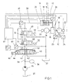
Zwei Ausführungsbeispiele einer erfindungsgemäßen hydraulischen Steuerung für eine hydraulisch betätigbare Kupplungsbremskombination für die Antriebswelle einer mechanischen Presse sind in den Figuren dargestellt. Anhand dieser Figuren wird die Erfindung nun näher erläutert.Two exemplary embodiments of a hydraulic control according to the invention for a hydraulically operated clutch / brake combination for the drive shaft a mechanical press are shown in the figures. Based on these figures the invention will now be explained in more detail.
Es zeigen
- Figur 1
- ein erstes Ausführungsbeispiel, bei dem das Proportional-Wegeventil zwischen der Druckmittelquelle und zwei Sicherheitsventilen angeordnet ist und
- Figur 2
- das zweites Ausführungsbeispiel, bei dem das Proportional-Wegeventil auch als Sicherheitsventil benutzt wird.
- Figure 1
- a first embodiment in which the proportional directional valve is arranged between the pressure medium source and two safety valves and
- Figure 2
- the second embodiment in which the proportional directional control valve is also used as a safety valve.
In den beiden Figuren 1 und 2 ist der Stößel 10 einer Presse zu erkennen, der
über eine Koppelstange 11 mit einer Exzenterwelle 12 verbunden ist. Diese kann
mit Hilfe einer Kupplung-Brems-Kombination 13 von einem Elektromotor 14 über
eine Antriebswelle 15 mit Schwungrad angetrieben werden oder aber abgebremst
werden. Derartige Kupplungs-Brems-Kombinationen sind allgemein, zum Beispiel
aus der DE-PS 1 207 725 oder der US-A 3 200 917 bekannt, so daß sich hier eine
nähere Beschreibung erübrigt. Wird keine äußere Kraft aufgebracht, so ist durch
eine Federanordnung 16 die Kupplung gelöst und die Bremse wirksam. Gegen die
Federanordnung kann hydraulisch die Bremse gelöst und die Kupplung eingerückt
werden. Dazu dient ein einseitig wirkender Hydrozylinder 18, dessen Inneres
durch einen Kolben 19, an dem eine Kolbenstange 17 befestigt ist, in einen vollzylindrischen,
kolbenstangenabseitigen Druckraum 20 und in einen ringzylindrischen
kolbenseitigen Aufnahmeraum 21 für die als Schraubendruckfeder ausgebildete
Federanordnung 15 aufgeteilt ist. Bei von Druck entlasteten Druckraum 20 ist die
Bremse mit einer durch die Vorspannung der Schraubendruckfeder 15 bestimmten
Kraft betätigt. Bei einem Druckanstieg im Druckraum 20 verringert sich zunächst
die Bremskraft, bis schließlich der Druck einen der Vorspannung der
Schraubendruckfeder 15 äquivalenten Wert annimmt. Dann beginnen der Kolben
19 und die Kolbenstange 17 sich zu bewegen. Die Bremse ist gelöst. Nach kurzem
Hub, währenddessen der Druck im Druckraum 20 wegen der steigenden
Spannung der Schraubendruckfeder 15 geringfügig zunimmt, legen sich Teile der
Kupplung 13 aneinander. Das über die Kupplung 13 übertragbare Drehmoment
hängt nun von der Höhe des Druckes im Druckraum 20 ab.In the two Figures 1 and 2, the
Mit der Exzenterwelle ist ein Drehwinkelgeber oder ein Drehzahlgeber 22 und mit
der Antriebswelle ein Drehwinkelgeber oder ein Drehzahlgeber 23 gekoppelt. Zur
Erfassung von Zuständen des Pressenstößels 10 dient ein Beschleunigungssensor
24 und/oder ein Wegsensor 25. Schließlich ist ein weiterer Wegsensor 26 vorgesehen,
mit dem die Position der Kolbenstange 17 erfaßt werden kann.With the eccentric shaft is a rotary encoder or a
Der Hydrozylinder 18 wird mit Druckmittel von einer Druckmittelquelle aus gespeist,
die im wesentlichen eine Hydropumpe 35 und einen Hydrospeicher 36
umfaßt. Die Hydropumpe 35 mit konstantem Hubvolumen wird von einem Elektromotor
angetrieben und saugt aus einem Tank 37 pro Zeiteinheit eine relativ
kleine Druckmittelmenge an, die sie in einen Druckleitung 38 abgibt, an die auch
der Hydrospeicher 36 angeschlossen ist.The
Die Einspeisung von Druckmittel in den Druckraum 20 und den Ablauf von
Druckmittel aus dem Druckraum wird bei beiden gezeigten Ausführungsbeispielen
durch ein elektrisch proportional verstellbares Wegeventil und wenigstens ein
weiteres elektrisch umschaltbares Wegeventil gesteuert. Bei dem Ausführungsbeispiel
nach Figur 1 ist ein Proportional-Wegeventil 40 mit einem mit der Druckleitung
38 verbundenen Druckanschluß 41, einem mit dem Tank 37 verbundenen
Tankanschluß 42 und mit einem Verbraucheranschluß 43 vorhanden. Das Wegeventil
40 ist von einer federzentrierten Mittelstellung mit negativer Überdeckung
der drei genannten Anschlüsse aus, durch Ansteuerung eines Elektromagneten
44 bzw. eines Elektromagneten 45 nach entgegengesetzten Richtungen stetig
verstellbar, wobei bei einer Verstellung in die eine Richtung ein Öffnungsquerschnitt
zwischen dem Druckanschluß und dem Arbeitsanschluß und bei einer Verstellung
in die entgegengesetzte Richtung ein Öffnungsquerschnitt zwischen dem
Arbeitsanschluß und dem Tankanschluß stetig vergrößert wird. Die Verbindung
des Arbeitsanschlusses zum jeweiligen anderen Anschluß wird dagegen schon
nach kurzem Weg vollständig geschlossen. Der Weg des Steuerkolbens des Wegeventils
40 wird durch einen Weggeber 46 erfaßt.The feeding of pressure medium into the
Zwischen den Verbraucheranschluß 43 des Wegeventils 40 und dem Hydrozylinder
18 sind als Sicherheitsventile zwei 4/2-Wege-Schaltventile 48 und 49 eingefügt,
die von denen jedes einen mit dem Tank37 verbunden Tankanschluß und
einen ersten Verbraucheranschluß aufweist, der an eine zum Druckraum 20 des
Hydrozylinders 18 führende Hydroleitung 50 angeschlossen ist. Beide Ventile 48
und 49 haben einen Druckanschluß, wobei der Druckanschluß des Ventils 48 mit
dem Verbraucheranschluß des Wegeventils 40 und der Druckanschluß des Ventils
49 mit einem zweiten Verbraucheranschluß des Ventils 48 verbunden ist. Ein
zweiter Verbraucheranschluß des Ventils 49 ist wie dessen erster Verbraucheranschluß
an die Hydroleitung 50 gelegt.Between the
Die beiden Ventile 48 und 49 nehmen unter der Wirkung einer Feder 51 eine Ruhestellung
ein, in der jedes für sich die Hydroleitung 50 mit dem Tank 37 verbindet.
Die beiden weiteren Anschlüsse (Druckanschluß und zweiter Verbraucheranschluß)
jedes Wegeventils 48 und 49 sind in der Ruhestellung dieser Ventile abgesperrt.
Befinden sich dagegen beide Wegeventile 48 und 49 in ihrer Arbeitsstellung,
in diese durch Bestromung von jeweils einem Elektromagneten 52 gebracht
werden können, so besteht über die beiden weiteren Anschlüsse des Wegeventils
48 und die in Serie dazu liegenden weiteren Anschlüsse des Wegeventils
49 eine Verbindung zwischen dem Druckraum 20 und dem Verbraucheranschluß
43 des Wegeventils 40. Somit ist, wenn sich auch nur eines der beiden
Wegeventile in seiner Ruhestellung befindet, der Druckraum 20 des Hydrozylinders
18 von Druck entlastet. Jedes der beiden Ventile 48 und 49 ist mit einem
Schaltstellungsgeber 53 ausgestattet, der ein Signal abgibt, wenn ein Ventil umschaltet.
Unterbleibt ein solches Signal, obwohl umgeschaltet werden soll, wird die
Anlage stillgesetzt.The two
An die Hydroleitung 50 ist eine Druckmeßdose 60 angeschlossen, von der somit
der Druck in dem Druckraum 20 des Hydrozylinders 18 erfaßbar ist. Alternativ
kann die Druckmeßdose 60 auch unmittelbar am Verbraucheranschluß 43 des
Wegeventils 40 sitzen, da dort bei geschalteten Ventilen 48 und 49 wenigstens
annähernd der gleiche Druck wie in der Leitung 50 herrscht. Das elektrische Ausgangssignal
der Druckmeßdose 60 sowie der Sensoren 22, 23, 24, 25 und 26
werden an eine Regelelektronik 61 gegeben, von der über einen Verstärker die
Elektromagnete 44 und 45 des Wegeventils 40 angesteuert werden.A
Im Ruhezustand der Presse wird der Pressenstößel 10 durch die Bremse der
Kupplungsbremskombination, oberen Totpunkt gehalten. Zu Beginn eines Pressenzyklus
werden die beiden Sicherheitsventil 48 und 49 umgeschaltet. Die Regelelektronik
steuert nun den Öffnungsquerschnitt zwischen den Anschlüssen 41
und 43 des Wegeventils 40 so, daß sich der Kolben 19 des Hydrozylinders 18 mit
einer gewünschten und über den Wegaufnehmer 26 rückgemeldeten Geschwindigkeit
bewegt und dabei die Bremse löst und die Kupplungsteile aneinanderfährt.
Das Auftreffen der Kupplungsteile aufeinander mit einer kontrollierten, also reduzierter
Geschwindigkeit läßt dabei keine oder nur kleine Drucküberschwinger entstehen.
Anschließend wird durch Zufuhr von Druckmittel von der Druckmittelquelle
über die Anschlüsse 41 und 43 des Wegeventils 40 in den Druckraum 20 und
durch Abfuhr von Druckmittel aus dem Druckraum über die beiden Anschlüsse 43
und 42 des Wegeventils 40 zum Tank 37 der Druck in dem Druckraum 20 entsprechend
einem gewünschten Druckprofil geregelt. Die Regelelektronik 61 ermöglicht
in Verbindung mit den Drehwinkel- oder Drehzahlsensoren 22 und 23 an
der Exzenterwelle 12 und an der Antriebswelle 15 eine weiterführende Regelung
des Kupplungsvorganges. Denkbar ist zum Beispiel eine Schlupfregelung zur
Schaltzeitminimierung oder Verschleißoptimierung. Ebenso denkbar ist zum Beispiel
eine Beschleunigungsregelung während des Kuppel- oder Bremsvorganges
mit Hilfe der Sensoren 24 und 25.In the idle state of the press, the
Wie beim Beginn eines Pressenzyklus kann auch an dessen Ende der Druck in
dem Druckraum 20 geregelt und der Kolben geregelt zurückgefahren werden.As at the beginning of a press cycle, the pressure in
the
Bei dem Ausführungsbeispiel nach Figur 2 ist nur ein einziges 4/2-Wege-Schaltventil,
das mit 48 bezeichnet sein möge, als Sicherheitsventil verwendet.
Das zweite Sicherheitsventil ist durch das vorhandene stetig verstellbare Wegeventil
70 realisiert, das wie das Wegeventil 40 aus Figur 1 einen Druckanschluß
41, einen unmittelbar mit dem Tank 37 verbunden Tankanschluß 42 und zwei mit
der Leitung 50 verbundene Verbraucheranschlüsse 43 aufweist. Das Wegeventil
70 ist also nun unmittelbar dem Druckraum 20 vorgeschaltet. Natürlich würde
auch ein einziger mit der Leitung 50 verbundener Verbraucheranschluß genügen.
Mit dem Wegeventil 70 zu einer Baueinheit zusammengefaßt und in dieses integriert
ist die Druckmeßdose 60, die unmittelbar in einem Verbraucheranschluß 43
den Druck abgreift, und die Regelelektronik 61. Die Position des Steuerkolbens
des Wegeventils 70 ist durch einen Weggeber 46 erfaßbar. Außerdem überwacht
ein Schaltstellungsgeber 53 das Wegeventil 70.In the embodiment according to FIG. 2 there is only a single 4/2-way switching valve,
which may be designated 48, used as a safety valve.
The second safety valve is due to the continuously adjustable
Das Wegeventil 70 nimmt unter der Wirkung einer Feder 71 eine Endstellung ein,
in der die Leitung 50 und damit der Druckraum 20 des Hydrozylinders 18 über einen
Verbraucheranschluß 43 und den Tankanschluß 42 zum Tank 37 entlastet
sind. Durch einen Elektromagneten 45 kann das Wegeventil 70 aus der Endstellung
heraus stetig in die eine Richtung verstellt werden, wobei der Öffnungsquerschnitt
zwischen den beiden Anschlüssen 42 und 43 immer kleiner gemacht wird,
ehe nach einer Phase negativer Überdeckung zwischen den Anschlüssen, nach
der der Tankanschluß abgesperrt ist, ein Öffnungsquerschnitt zwischen dem
Druckanschluß 41 und einem Verbraucheranschluß 43 immer mehr aufgemacht
wird.The
Das Sicherheitsventil 48 hat einen mit der Druckleitung 38 verbundenen Druckanschluß,
einen mit dem Tank 37 verbundenen Tankanschluß, einen mit der Hydroleitung
50 verbundenen ersten Verbraucheranschluß und einen mit dem Druckanschluß
41 des Wegeventils 70 verbundenen zweiten Verbraucheranschluß und
nimmt unter der Wirkung einer Feder 51 eine Ruhestellung ein, in der der erste
Verbraucheranschluß mit dem Tankanschluß, also die Hydroleitung 50 mit dem
Tank 37 verbunden ist. Die beiden weiteren Anschlüsse (Druckanschluß und
zweiter Verbraucheranschluß) des Wegeventils 48 sind in der Ruhestellung abgesperrt.
Nach Umschaltung des Wegeventils 48 sind der Druckanschluß und der
zweite Verbraucheranschluß miteinander verbunden und die beiden anderen Anschlüsse
abgesperrt. Somit entlastet in der Ruhestellung jedes der beiden Wegeventile
48 und 70 den Druckraum 20 für sich allein zum Tank. Also müssen beide
Wegeventile aus ihre Ruhestellung gebracht worden sein, damit ein Zufluß von
Druckmittel zum Druckraum 20 möglich ist.The
Beim Ausführungsbeispiel nach Figur 2 ist beim Kupplungs- und beim Bremsvorgang
ein Regelung der Geschwindigkeit des Kolbens19 und des Drucks im Druckraum
20 in derselben Weise wie bei dem Ausführungsbeispiel nach Figur 1 mit
dem proportional verstellbaren Wegeventil 70, der Regelelektronik 61 und den
verschieden Sensoren möglich. Darüber hinaus erfüllt das zur Regelung benutzte
Wegeventil auch die Funktion eines Sicherheitsventils. Das Sicherheitsventil 48
kann in Zwischenplattenbauweise unmittelbar am Wegeventil 70 sitzen: Insgesamt
erhält man somit einen kompakten Steuerungsmodul mit den benötigten
Ventilen, der Regelelektronik und der Druckmeßdose.In the embodiment of Figure 2 is the clutch and braking
a control of the speed of the
Claims (6)
und mit einem proportional verstellbaren Regelventil (40, 70), mit dem der Druck einstellbar ist, von dem der Hydrozylinder (18) beaufschlagt ist,
dadurch gekennzeichnet, daß ein elektrischer Drucksensor (60) vorhanden ist, von dem der den Hydrozylinder (18) beaufschlagende Druck erfaßbar ist,
daß eine Regelelektronik (61) vorhanden ist, dem ein dem erfaßten Druck entsprechendes elektrisches Signal des Drucksensors (60) zugeführt wird
und daß das Regelventil (40, 70) ein elektrisch ansteuerbares Proportional-Wegeventil ist, das von der Regelelektronik (61) entsprechend dem erfaßten Ist-Druck und dem gewünschten Soll-Druck angesteuert wird.Hydraulic control for a hydraulically actuated clutch / brake combination (13), in particular on the eccentric shaft (12) of a mechanical press with a hydraulic pump (35) and preferably also a hydraulic accumulator (36) to supply a hydraulic cylinder that actuates the clutch and / or the brake ( 18) with pressure medium, with a safety valve arrangement (48, 49) which has a pressure connection via which a flow path leads from the pressure medium source (35, 36) to the hydraulic cylinder (18),
and with a proportionally adjustable control valve (40, 70) with which the pressure can be set by which the hydraulic cylinder (18) is acted upon,
characterized in that there is an electrical pressure sensor (60) from which the pressure acting on the hydraulic cylinder (18) can be detected,
that control electronics (61) are present, to which an electrical signal corresponding to the detected pressure of the pressure sensor (60) is supplied
and that the control valve (40, 70) is an electrically controllable proportional directional control valve which is controlled by the control electronics (61) in accordance with the detected actual pressure and the desired set pressure.
Applications Claiming Priority (4)
| Application Number | Priority Date | Filing Date | Title |
|---|---|---|---|
| DE10060083 | 2000-12-02 | ||
| DE10060083 | 2000-12-02 | ||
| DE10062229 | 2000-12-13 | ||
| DE10062229A DE10062229A1 (en) | 2000-12-02 | 2000-12-13 | Hydraulic control for a hydraulically actuated clutch / brake combination, in particular on the eccentric shaft of a mechanical press |
Publications (3)
| Publication Number | Publication Date |
|---|---|
| EP1211059A2 true EP1211059A2 (en) | 2002-06-05 |
| EP1211059A3 EP1211059A3 (en) | 2003-04-16 |
| EP1211059B1 EP1211059B1 (en) | 2006-08-16 |
Family
ID=26007867
Family Applications (1)
| Application Number | Title | Priority Date | Filing Date |
|---|---|---|---|
| EP20010127201 Expired - Lifetime EP1211059B1 (en) | 2000-12-02 | 2001-11-16 | Hydraulic control system for a hydraulically actuated clutch-brake combination in particular for the eccentric shaft of a mechanical press |
Country Status (3)
| Country | Link |
|---|---|
| EP (1) | EP1211059B1 (en) |
| DE (1) | DE50110744D1 (en) |
| ES (1) | ES2267653T3 (en) |
Cited By (2)
| Publication number | Priority date | Publication date | Assignee | Title |
|---|---|---|---|---|
| DE102008051209A1 (en) * | 2008-10-14 | 2010-04-15 | Ortlinghaus-Werke Gmbh | Control system for influencing the ram dynamics in press machines |
| EP3067192A1 (en) * | 2015-03-09 | 2016-09-14 | Ortlinghaus-Werke GmbH | Control device, system and method for operating a clutch or brake |
Citations (8)
| Publication number | Priority date | Publication date | Assignee | Title |
|---|---|---|---|---|
| US3200917A (en) * | 1963-05-14 | 1965-08-17 | Ortlinghaus Geb | Air cooled compact clutch and brake |
| DE2935702A1 (en) * | 1979-09-04 | 1981-03-12 | Herion-Werke Kg, 7012 Fellbach | Eccentric press clutch and brake control circuit - has distribution valve assembly with operation dependent on pressure of clutch and brake respectively |
| WO1986000849A1 (en) * | 1984-07-19 | 1986-02-13 | Zf-Herion-Systemtechnik Gmbh | Pressure-adjusting system for a hydraulically-operated clutch and/or brake for the drive shaft of a press |
| US4580674A (en) * | 1980-10-31 | 1986-04-08 | L. Schuler Gmbh | Control arrangement for the actuating pressure applied to a clutch and/or brake of a mechanical press |
| DD256851A1 (en) * | 1986-12-31 | 1988-05-25 | Warnke Umformtech Veb K | DEVICE FOR CONTROLLING THE MOMENT PROCESSING OF PRESSURE-RELATED FRICTION COUPLINGS OR BZW. BRAKING TO PRESSES |
| DE4314801A1 (en) * | 1993-05-05 | 1994-11-10 | Rexroth Mannesmann Gmbh | Hydraulic system, in particular for a folding press |
| EP0829342A1 (en) * | 1996-02-02 | 1998-03-18 | Goizper, S. Coop. | Hydraulic system for controlling brakes, clutches and brakes-clutches |
| DE19831144A1 (en) * | 1998-07-11 | 2000-01-13 | Mannesmann Rexroth Ag | Hydraulic control for a hydraulically operated clutch / brake combination for the drive shaft of a mechanical press |
-
2001
- 2001-11-16 DE DE50110744T patent/DE50110744D1/en not_active Expired - Lifetime
- 2001-11-16 EP EP20010127201 patent/EP1211059B1/en not_active Expired - Lifetime
- 2001-11-16 ES ES01127201T patent/ES2267653T3/en not_active Expired - Lifetime
Patent Citations (8)
| Publication number | Priority date | Publication date | Assignee | Title |
|---|---|---|---|---|
| US3200917A (en) * | 1963-05-14 | 1965-08-17 | Ortlinghaus Geb | Air cooled compact clutch and brake |
| DE2935702A1 (en) * | 1979-09-04 | 1981-03-12 | Herion-Werke Kg, 7012 Fellbach | Eccentric press clutch and brake control circuit - has distribution valve assembly with operation dependent on pressure of clutch and brake respectively |
| US4580674A (en) * | 1980-10-31 | 1986-04-08 | L. Schuler Gmbh | Control arrangement for the actuating pressure applied to a clutch and/or brake of a mechanical press |
| WO1986000849A1 (en) * | 1984-07-19 | 1986-02-13 | Zf-Herion-Systemtechnik Gmbh | Pressure-adjusting system for a hydraulically-operated clutch and/or brake for the drive shaft of a press |
| DD256851A1 (en) * | 1986-12-31 | 1988-05-25 | Warnke Umformtech Veb K | DEVICE FOR CONTROLLING THE MOMENT PROCESSING OF PRESSURE-RELATED FRICTION COUPLINGS OR BZW. BRAKING TO PRESSES |
| DE4314801A1 (en) * | 1993-05-05 | 1994-11-10 | Rexroth Mannesmann Gmbh | Hydraulic system, in particular for a folding press |
| EP0829342A1 (en) * | 1996-02-02 | 1998-03-18 | Goizper, S. Coop. | Hydraulic system for controlling brakes, clutches and brakes-clutches |
| DE19831144A1 (en) * | 1998-07-11 | 2000-01-13 | Mannesmann Rexroth Ag | Hydraulic control for a hydraulically operated clutch / brake combination for the drive shaft of a mechanical press |
Cited By (4)
| Publication number | Priority date | Publication date | Assignee | Title |
|---|---|---|---|---|
| DE102008051209A1 (en) * | 2008-10-14 | 2010-04-15 | Ortlinghaus-Werke Gmbh | Control system for influencing the ram dynamics in press machines |
| DE102008051209B4 (en) * | 2008-10-14 | 2012-02-16 | Ortlinghaus-Werke Gmbh | Control system for influencing the ram dynamics in press machines |
| EP2177346A3 (en) * | 2008-10-14 | 2013-01-30 | Ortlinghaus-Werke GmbH | Control system for influence on the ram dynamics in press machines |
| EP3067192A1 (en) * | 2015-03-09 | 2016-09-14 | Ortlinghaus-Werke GmbH | Control device, system and method for operating a clutch or brake |
Also Published As
| Publication number | Publication date |
|---|---|
| ES2267653T3 (en) | 2007-03-16 |
| EP1211059A3 (en) | 2003-04-16 |
| EP1211059B1 (en) | 2006-08-16 |
| DE50110744D1 (en) | 2006-09-28 |
Similar Documents
| Publication | Publication Date | Title |
|---|---|---|
| DE60120061T2 (en) | Hydraulic system with crossed energy recovery | |
| DE19849311A1 (en) | Track chain tension control system | |
| WO2000007796A1 (en) | Hydrostatic drive system for an injection molding machine and a method for operating such a drive system | |
| DE2528094A1 (en) | CONTROL SYSTEM FOR HYDROSTATIC TRANSMISSION | |
| DE3709504C2 (en) | Valve device | |
| DE19781771B3 (en) | Back pressure control circuit for hydraulic drive device | |
| DE4424790A1 (en) | Hydraulic emergency control for a friction clutch arranged between an internal combustion engine and a transmission | |
| DE3644769C2 (en) | ||
| EP2655895B1 (en) | Hydraulic drive | |
| DE4036564A1 (en) | Hydraulic system for control of press RAM - provides fast approach with high forming load by use of nested cylinders controlled by multiway proportional valve | |
| EP1097039B1 (en) | Hydraulic control system for a hydraulically actuated clutch brake combination for the drive shaft of a mechanical press | |
| EP0216776B1 (en) | Pressure-adjusting system for a hydraulically-operated clutch and/or brake for the drive shaft of a press | |
| DE4405234C1 (en) | Arrangement for the cumulative power regulation of at least two hydrostatic variable-displacement pumps | |
| WO1986004963A1 (en) | Proportional valve with variable pre-loading of the balance spring non-proportionally to the load pressure | |
| WO1995034399A1 (en) | Hydraulic control system for a cutting machine tool | |
| EP0914575A1 (en) | Emergency hydraulic control for adjusting a constant clamping force ratio with regard to a continuously variable transmission | |
| EP1211059B1 (en) | Hydraulic control system for a hydraulically actuated clutch-brake combination in particular for the eccentric shaft of a mechanical press | |
| DE3630681C2 (en) | Brake system for conveyor systems | |
| DE3711233A1 (en) | DRIVE DEVICE WITH A PRIMARY ENERGY SOURCE, A GEARBOX AND A PUMP | |
| WO2000026563A1 (en) | Hydrostatic gear unit | |
| EP0836559B1 (en) | Inching and braking system with interconnected brake and inching valves | |
| EP0561153A1 (en) | Capacity regulating device for at least two hydrostatic variable displacement pumps | |
| DE3404927A1 (en) | Hydraulic control device for the injection unit of a plastics injection moulding machine | |
| DE2532768B2 (en) | Hydraulic servo motor system | |
| DE2943642A1 (en) | DEVICE FOR CONTROLLING A SIMPLY WORKING CYLINDER, IN PARTICULAR A PRESS WORKING CYLINDER |
Legal Events
| Date | Code | Title | Description |
|---|---|---|---|
| PUAI | Public reference made under article 153(3) epc to a published international application that has entered the european phase |
Free format text: ORIGINAL CODE: 0009012 |
|
| AK | Designated contracting states |
Kind code of ref document: A2 Designated state(s): AT BE CH CY DE DK ES FI FR GB GR IE IT LI LU MC NL PT SE TR |
|
| AX | Request for extension of the european patent |
Free format text: AL;LT;LV;MK;RO;SI |
|
| RAP1 | Party data changed (applicant data changed or rights of an application transferred) |
Owner name: BOSCH REXROTH AG |
|
| PUAL | Search report despatched |
Free format text: ORIGINAL CODE: 0009013 |
|
| AK | Designated contracting states |
Designated state(s): AT BE CH CY DE DK ES FI FR GB GR IE IT LI LU MC NL PT SE TR |
|
| AX | Request for extension of the european patent |
Extension state: AL LT LV MK RO SI |
|
| 17P | Request for examination filed |
Effective date: 20030915 |
|
| AKX | Designation fees paid |
Designated state(s): DE ES FR IT SE |
|
| GRAP | Despatch of communication of intention to grant a patent |
Free format text: ORIGINAL CODE: EPIDOSNIGR1 |
|
| GRAS | Grant fee paid |
Free format text: ORIGINAL CODE: EPIDOSNIGR3 |
|
| GRAA | (expected) grant |
Free format text: ORIGINAL CODE: 0009210 |
|
| AK | Designated contracting states |
Kind code of ref document: B1 Designated state(s): DE ES FR IT SE |
|
| PG25 | Lapsed in a contracting state [announced via postgrant information from national office to epo] |
Ref country code: IT Free format text: LAPSE BECAUSE OF FAILURE TO SUBMIT A TRANSLATION OF THE DESCRIPTION OR TO PAY THE FEE WITHIN THE PRESCRIBED TIME-LIMIT;WARNING: LAPSES OF ITALIAN PATENTS WITH EFFECTIVE DATE BEFORE 2007 MAY HAVE OCCURRED AT ANY TIME BEFORE 2007. THE CORRECT EFFECTIVE DATE MAY BE DIFFERENT FROM THE ONE RECORDED. Effective date: 20060816 |
|
| REF | Corresponds to: |
Ref document number: 50110744 Country of ref document: DE Date of ref document: 20060928 Kind code of ref document: P |
|
| REG | Reference to a national code |
Ref country code: SE Ref legal event code: TRGR |
|
| ET | Fr: translation filed | ||
| REG | Reference to a national code |
Ref country code: ES Ref legal event code: FG2A Ref document number: 2267653 Country of ref document: ES Kind code of ref document: T3 |
|
| PLBE | No opposition filed within time limit |
Free format text: ORIGINAL CODE: 0009261 |
|
| STAA | Information on the status of an ep patent application or granted ep patent |
Free format text: STATUS: NO OPPOSITION FILED WITHIN TIME LIMIT |
|
| 26N | No opposition filed |
Effective date: 20070518 |
|
| PGFP | Annual fee paid to national office [announced via postgrant information from national office to epo] |
Ref country code: SE Payment date: 20071126 Year of fee payment: 7 |
|
| PGFP | Annual fee paid to national office [announced via postgrant information from national office to epo] |
Ref country code: FR Payment date: 20071120 Year of fee payment: 7 |
|
| EUG | Se: european patent has lapsed | ||
| REG | Reference to a national code |
Ref country code: FR Ref legal event code: ST Effective date: 20090731 |
|
| PG25 | Lapsed in a contracting state [announced via postgrant information from national office to epo] |
Ref country code: SE Free format text: LAPSE BECAUSE OF NON-PAYMENT OF DUE FEES Effective date: 20081117 |
|
| PG25 | Lapsed in a contracting state [announced via postgrant information from national office to epo] |
Ref country code: FR Free format text: LAPSE BECAUSE OF NON-PAYMENT OF DUE FEES Effective date: 20081130 |
|
| PGFP | Annual fee paid to national office [announced via postgrant information from national office to epo] |
Ref country code: ES Payment date: 20181218 Year of fee payment: 18 Ref country code: IT Payment date: 20181122 Year of fee payment: 18 |
|
| PGFP | Annual fee paid to national office [announced via postgrant information from national office to epo] |
Ref country code: DE Payment date: 20190124 Year of fee payment: 18 |
|
| REG | Reference to a national code |
Ref country code: DE Ref legal event code: R119 Ref document number: 50110744 Country of ref document: DE |
|
| PG25 | Lapsed in a contracting state [announced via postgrant information from national office to epo] |
Ref country code: IT Free format text: LAPSE BECAUSE OF NON-PAYMENT OF DUE FEES Effective date: 20191116 Ref country code: DE Free format text: LAPSE BECAUSE OF NON-PAYMENT OF DUE FEES Effective date: 20200603 |
|
| REG | Reference to a national code |
Ref country code: ES Ref legal event code: FD2A Effective date: 20210527 |
|
| PG25 | Lapsed in a contracting state [announced via postgrant information from national office to epo] |
Ref country code: ES Free format text: LAPSE BECAUSE OF NON-PAYMENT OF DUE FEES Effective date: 20191117 |