EP1211013B1 - Verfahren zum Verbinden eines Befestigungsauges mit dem Boden eines Schwingungsdämpfers und Bausystem, umfassend ein Befestigungsauge und einen Boden - Google Patents
Verfahren zum Verbinden eines Befestigungsauges mit dem Boden eines Schwingungsdämpfers und Bausystem, umfassend ein Befestigungsauge und einen Boden Download PDFInfo
- Publication number
- EP1211013B1 EP1211013B1 EP01125824A EP01125824A EP1211013B1 EP 1211013 B1 EP1211013 B1 EP 1211013B1 EP 01125824 A EP01125824 A EP 01125824A EP 01125824 A EP01125824 A EP 01125824A EP 1211013 B1 EP1211013 B1 EP 1211013B1
- Authority
- EP
- European Patent Office
- Prior art keywords
- shaped groove
- welding
- fixing eyelet
- vibration damper
- shaped
- Prior art date
- Legal status (The legal status is an assumption and is not a legal conclusion. Google has not performed a legal analysis and makes no representation as to the accuracy of the status listed.)
- Expired - Lifetime
Links
Images

Classifications
-
- B—PERFORMING OPERATIONS; TRANSPORTING
- B23—MACHINE TOOLS; METAL-WORKING NOT OTHERWISE PROVIDED FOR
- B23K—SOLDERING OR UNSOLDERING; WELDING; CLADDING OR PLATING BY SOLDERING OR WELDING; CUTTING BY APPLYING HEAT LOCALLY, e.g. FLAME CUTTING; WORKING BY LASER BEAM
- B23K11/00—Resistance welding; Severing by resistance heating
- B23K11/002—Resistance welding; Severing by resistance heating specially adapted for particular articles or work
- B23K11/004—Welding of a small piece to a large or broad piece
- B23K11/0046—Welding of a small piece to a large or broad piece the extremity of a small piece being welded to a base, e.g. cooling studs or fins to tubes or plates
- B23K11/006—Welding a tip to a base, e.g. pen point nibs
-
- F—MECHANICAL ENGINEERING; LIGHTING; HEATING; WEAPONS; BLASTING
- F16—ENGINEERING ELEMENTS AND UNITS; GENERAL MEASURES FOR PRODUCING AND MAINTAINING EFFECTIVE FUNCTIONING OF MACHINES OR INSTALLATIONS; THERMAL INSULATION IN GENERAL
- F16F—SPRINGS; SHOCK-ABSORBERS; MEANS FOR DAMPING VIBRATION
- F16F9/00—Springs, vibration-dampers, shock-absorbers, or similarly-constructed movement-dampers using a fluid or the equivalent as damping medium
- F16F9/32—Details
- F16F9/3207—Constructional features
- F16F9/3235—Constructional features of cylinders
- F16F9/3242—Constructional features of cylinders of cylinder ends, e.g. caps
-
- B—PERFORMING OPERATIONS; TRANSPORTING
- B23—MACHINE TOOLS; METAL-WORKING NOT OTHERWISE PROVIDED FOR
- B23K—SOLDERING OR UNSOLDERING; WELDING; CLADDING OR PLATING BY SOLDERING OR WELDING; CUTTING BY APPLYING HEAT LOCALLY, e.g. FLAME CUTTING; WORKING BY LASER BEAM
- B23K2101/00—Articles made by soldering, welding or cutting
- B23K2101/04—Tubular or hollow articles
- B23K2101/06—Tubes
Definitions
- the invention relates to a compound of a fastening eye with the bottom of a vibration damper by means of welding.
- Fixing eyes are used for mounting vibration dampers for motor vehicles on the vehicle body and / or on the suspension.
- the connection of the fastening eye with the bottom of a vibration damper not only has to withstand large loads, the connection must also be absolutely safe, as in a destruction of this compound, the driving safety of the vehicle would no longer exist.
- fastening eyes it is known to connect fastening eyes to the bottom of a vibration damper by means of welding.
- the fastening eyes are produced as a ring and preferably connected by means of resistance-pressure welding or inert gas welding to the bottom of the vibration damper.
- a disadvantage of the previous welding process is the need for accurate positioning of the fastening eye on the ground, which is possible only with high device complexity, and further disadvantage is only a low fatigue strength to achieve.
- the invention has for its object to reduce the device complexity and to make the welding process safer.
- the advantages achieved by the invention are, in particular, that it is no longer necessary to perform the welding under protective gas.
- This advantage results from the fact that the welding begins when placing the fastening eye on the side edges of the W-shaped groove. Therefore, welding is done from outside to the center. Due to the formation of the groove with a W-shape comes later the V-shaped outwardly opening longitudinal joint of the fastening eye with the middle elevation of the W-shaped groove in combination. This leads to the completion of the weld to a lateral form fit. This positive connection leads to an increased fatigue strength with changing load.
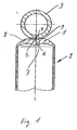
- a vibration damper in particular for motor vehicles, has a damper cylinder 2 provided with a bottom 1. With the bottom 1, a fastening eye 3 is connected by welding. From Fig. 1, the weld preparation of floor 1 and mounting eye 3 can be seen.
- the attachment eye 3 is preferably made of a strip of sheet material by rolling or bending. After rolling or bending, the ends of the flat material form a longitudinal joint 4 which opens out in a V-shape to the outside.
- a W-shaped groove is made in the bottom 1 of the damper cylinder 2 by broaching or milling. This W-shaped groove is composed of two adjacent curves 5, 6 together. The curves 5, 6 are in the exemplary embodiment radii with the same curvature.
- This form leads in the center of the W-shaped groove to a central elevation 7.
- the attachment eye 3 rests on the side edges 8, 9 of the groove.
- the groove is dimensioned such that in this case the elevation 7 does not touch the fastening eye 3.
- the elevation 7 is approximately centrally opposite the V-shaped outwardly opening longitudinal joint 4 of the fastening eye 3. This ensures that the intended resistance-pressure welding the welding process from the outside (den Side edges 8, 9) starting inward to the survey 7 progressively takes place. Since this causes the heating of the elevation 7 only at the very end, there is a positive connection between the elevation 7 and the longitudinal joint. 4
- the finished weld is shown in FIG.
- the selected welding criteria of the longitudinal joint 4 is more or less filled with weld metal.
- the welding together of the damper cylinder 2 on the longitudinal joint 4 is of minor importance for the durability of the welded joint.
Landscapes
- Engineering & Computer Science (AREA)
- Mechanical Engineering (AREA)
- General Engineering & Computer Science (AREA)
- Fluid-Damping Devices (AREA)
- Butt Welding And Welding Of Specific Article (AREA)
- Buildings Adapted To Withstand Abnormal External Influences (AREA)
- Standing Axle, Rod, Or Tube Structures Coupled By Welding, Adhesion, Or Deposition (AREA)
- Vehicle Body Suspensions (AREA)
Description
- Die Erfindung betrifft eine Verbindung eines Befestigungsauges mit dem Boden eines Schwingungsdämpfers mittels Schweißen. Befestigungsaugen dienen zum Befestigen von Schwingungsdämpfern für Kraftfahrzeuge am Kraftfahrzeugaufbau und/oder an der Radaufhängung. Die Verbindung des Befestigungsauges mit dem Boden eines Schwingungsdämpfers muss nicht nur großen Belastungen standhalten, die Verbindung muss auch unbedingt sicher sein, da bei einer Zerstörung dieser Verbindung die Fahrsicherheit des Fahrzeuges nicht mehr gegeben wäre.
- Es ist bekannt, Befestigungsaugen mit dem Boden eines Schwingungsdämpfers mittels Schweißen zu verbinden. Dabei werden die Befestigungsaugen als Ring hergestellt und vorzugsweise mittels Widerstands-Press-Schweißen oder Schutzgasschweißen mit dem Boden des Schwingungsdämpfers verbunden.
- So ist beispielsweise aus der
US-A- 2 106 272 bekannt, einen Befestigungsring mit dem Boden eines Schwingungsdämpfers durch Widerstands-Press-Schweißen zu verbinden. Hierzu wird der Befestigungsring gegen den Boden des Schwingungsdämpfers gepresst, sodass es aufgrund des Kontakts des Befestigungsrings mit dem Boden zu einer Schweißverbindung zwischen den einander kontaktierenden Oberflächen kommt. - Nachteilig bei den bisherigen Schweißverfahren ist die Notwendigkeit einer genauen Positionierung des Befestigungsauges am Boden, die nur unter hohem Vorrichtungsaufwand möglich ist, und weiterhin nachteilig ist nur eine geringe Dauerfestigkeit zu erreichen.
- Der Erfindung liegt die Aufgabe zugrunde, den Vorrichtungsaufwand zu verringern und das Schweißverfahren sicherer zu gestalten.
- Diese Aufgabe wird erfindungsgemäß mit den Merkmalen des Anspruchs 1 und den Merkmalen des Anspruchs 4 gelöst. Vorteilhafte Aus- und Weiterbildungen sind in den Unteransprüchen 2 und 3 sowie im Unteranspruch 5 angegeben.
- Die mit der Erfindung erzielten Vorteile bestehen insbesondere darin, dass es nicht mehr erforderlich ist, die Schweißung unter Schutzgas vorzunehmen. Dieser Vorteil ergibt sich dadurch, dass das Schweißen beim Aufsetzen des Befestigungsauges auf die Seitenkanten der W-förmigen Nut beginnt. Von daher erfolgt das Schweißen von außen zum Zentrum hin. Durch die Ausbildung der Nut mit einer W-Form kommt später der sich V-förmig nach außen öffnende Längsstoß des Befestigungsauges mit der mittleren Erhebung der W-förmigen Nut in Verbindung. Das führt zum Abschluss der Schweißung zu einem seitlichen Formschluss. Dieser Formschluss führt zu einer erhöhten Dauerfestigkeit bei wechselnder Belastung.
- Ein Ausführungsbeispiel der Erfindung ist in der Zeichnung dargestellt und wird im Folgenden näher beschrieben. Es zeigen
- Fig. 1 die Ausbildung der Schweißnahtvorbereitung vor dem Schweißen und
- Fig. 2 einen Schnitt durch den fertig verschweißten Schwingungsdämpfer.
- Ein Schwingungsdämpfer insbesondere für Kraftfahrzeuge weist einen mit einem Boden 1 versehenen Dämpferzylinder 2 auf. Mit dem Boden 1 wird ein Befestigungsauge 3 mittels Schweißen verbunden. Aus Fig. 1 ist die Schweißnahtvorbereitung von Boden 1 und Befestigungsauge 3 erkennbar. Das Befestigungsauge 3 wird vorzugsweise aus einem Streifen Flachmaterial durch Rollen oder Biegen hergestellt. Die Enden des Flachmaterials bilden nach dem Rollen oder Biegen einen sich V-förmig nach außen öffnenden Längsstoß 4. In den Boden 1 des Dämpferzylinders 2 wird durch Räumen oder Fräsen eine W-förmige Nut eingebracht. Diese W-förmige Nut setzt sich aus zwei nebeneinander liegenden Rundungen 5, 6 zusammen. Die Rundungen 5, 6 sind im Ausführungsbeispiel Radien mit gleicher Krümmung. Diese Form führt im Zentrum der W-förmigen Nut zu einer mittleren Erhebung 7. Vor dem Beginn der Schweißung werden Boden 1 und Befestigungsauge 3 in die in Fig. 1 dargestellte Position zueinander gebracht. Dabei liegt das Befestigungsauge 3 auf den Seitenkanten 8, 9 der Nut auf. Die Nut ist so bemessen, dass hierbei die Erhebung 7 das Befestigungsauge 3 nicht berührt. Die Erhebung 7 liegt etwa zentral gegenüber dem sich V-förmig nach außen öffnenden Längsstoß 4 des Befestigungsauges 3. Damit ist gewährleistet, dass beim vorgesehenen Widerstands-Press-Schweißen der Schweißvorgang von außen (den Seitenkanten 8, 9) beginnend nach innen zur Erhebung 7 fortschreitend erfolgt. Da dadurch die Erwärmung der Erhebung 7 erst ganz zum Schluss erfolgt, kommt es zu einem Formschluss zwischen der Erhebung 7 und dem Längsstoß 4.
- Die fertige Schweißung ist in Fig. 2 dargestellt. Je nach den gewählten Schweißkriterien ist der Längsstoß 4 mehr oder weniger mit Schweißgut gefüllt. Das Zusammenschweißen des Dämpferzylinders 2 am Längsstoß 4 ist für die Haltbarkeit der Schweißverbindung von untergeordneter Bedeutung.
-
- 1.
- Boden
- 2.
- Dämpferzylinder
- 3.
- Befestigungsauge
- 4.
- Längsstoß
- 5.
- Rundung
- 6.
- Rundung
- 7.
- Erhebung
- 8.
- Seitenkante
- 9.
- Seitenkante
Claims (5)
- Verfahren zum Verbinden eines Befestigungsauges (3) mit dem Boden (1) eines Schwingungsdämpfers mittels Schweißen, dadurch gekennzeichnet, dass vor dem Schweißen- das Befestigungsauge (3) vorzugsweise durch Rollen oder Biegen aus einem Streifen Flachmaterial hergestellt ist und einen sich V-förmig nach außen öffnenden Längsstoß (4) aufweist,- der Boden (1) eine quer verlaufende, sich aus zwei Rundungen (5, 6) zusammensetzende W-förmige Nut aufweist, deren Tiefe und mittlere Erhebung (7) so bemessen ist, dass das Befestigungsauge (3) auf den Seitenkanten (8, 9) der W-förmigen Nut aufliegt und- der V-förmige Längsstoß (4) des Befestigungsauges (3) zentral oder nahezu zentral über der mittleren Erhebung (7) der W-förmigen Nut liegt.
- Verfahren nach Anspruch 1, dadurch gekennzeichnet, dass das Schweißen durch Widerstands-Press-Schweißen erfolgt.
- Verfahren nach Anspruch 1 oder Anspruch 2, dadurch gekennzeichnet, dass die Rundungen (5, 6) der W-förmigen Nut durch Radien, vorzugsweise Radien mit gleicher Krümmung gebildet werden.
- Bausystem, umfassend ein Befestigungsauge (3) und einen Schwingungsdämpfer mit einem Boden (1), dessen Form abschnittsweise der Form des Befestigungsauges (3) angepasst ist, dadurch gekennzeichnet, dass- das Befestigungsauge (3) vorzugsweise durch Rollen oder Biegen aus einem Streifen Flachmaterial hergestellt ist und einen sich V-förmig nach außen öffnenden Längsstoß (4) aufweist,- der Boden (1) eine quer verlaufende, sich aus zwei Rundungen (5, 6) zusammensetzende W-förmigen Nut aufweist, deren Tiefe und mittlere Erhebung (7) so bemessen ist, dass das Befestigungsauge (3) auf den Seitenkanten (8, 9) der W-förmigen Nut aufliegt und- der V-förmige Längsstoß (4) des Befestigungsauges (3) zentral oder nahezu zentral über der mittleren Erhebung (7) der W-förmigen Nut liegt.
- Bausystem nach Anspruch 4, dadurch gekennzeichnet, dass die Rundungen (5, 6) der W-förmigen Nut durch Radien, vorzugsweise Radien mit gleicher Krümmung gebildet werden.
Applications Claiming Priority (2)
| Application Number | Priority Date | Filing Date | Title |
|---|---|---|---|
| DE10060057 | 2000-12-02 | ||
| DE10060057A DE10060057C2 (de) | 2000-12-02 | 2000-12-02 | Ausbildung eines Befestigungsauges und eines Bodens eines Schwingungsdämpfers |
Publications (3)
| Publication Number | Publication Date |
|---|---|
| EP1211013A2 EP1211013A2 (de) | 2002-06-05 |
| EP1211013A3 EP1211013A3 (de) | 2003-12-03 |
| EP1211013B1 true EP1211013B1 (de) | 2007-08-01 |
Family
ID=7665630
Family Applications (1)
| Application Number | Title | Priority Date | Filing Date |
|---|---|---|---|
| EP01125824A Expired - Lifetime EP1211013B1 (de) | 2000-12-02 | 2001-10-30 | Verfahren zum Verbinden eines Befestigungsauges mit dem Boden eines Schwingungsdämpfers und Bausystem, umfassend ein Befestigungsauge und einen Boden |
Country Status (4)
| Country | Link |
|---|---|
| US (1) | US6572008B2 (de) |
| EP (1) | EP1211013B1 (de) |
| DE (2) | DE10060057C2 (de) |
| ES (1) | ES2287064T3 (de) |
Cited By (1)
| Publication number | Priority date | Publication date | Assignee | Title |
|---|---|---|---|---|
| DE102009022057A1 (de) | 2009-05-20 | 2010-11-25 | Volkswagen Ag | Schwingungsdämpfer |
Families Citing this family (1)
| Publication number | Priority date | Publication date | Assignee | Title |
|---|---|---|---|---|
| CN101098768B (zh) * | 2004-11-30 | 2010-09-29 | 约翰逊控制技术公司 | 连接构件 |
Family Cites Families (16)
| Publication number | Priority date | Publication date | Assignee | Title |
|---|---|---|---|---|
| US2106272A (en) * | 1936-07-15 | 1938-01-25 | Gen Motors Corp | Shock absorber |
| DE1630449A1 (de) * | 1951-01-28 | 1971-06-03 | Fichtel & Sachs Ag | Schwingungsdaempfer oder Federung von teleskopartiger Bauform mit durch Widerstandsschweissung angebrachten Befestigungsaugen |
| US4061320A (en) * | 1976-05-03 | 1977-12-06 | Joe Frank Warner | Two cylinder shock absorber system |
| US4080782A (en) * | 1976-10-04 | 1978-03-28 | Lake City Manufacturing Co. | Swivel for cargo binders and the like |
| DE2735424A1 (de) * | 1977-08-05 | 1979-02-15 | Scharwaechter Gmbh Co Kg | Verfahren zur herstellung gerollter scharniere und nach diesem verfahren hergestelltes scharnier |
| US4561641A (en) * | 1978-09-18 | 1985-12-31 | Clark Equipment Company | Off-highway vehicle ride strut and method |
| GB2093546A (en) * | 1981-02-25 | 1982-09-02 | Allied Piping Prod Co | Branch connection fitting |
| US4996752A (en) * | 1981-04-20 | 1991-03-05 | Clendinen Charles D | Stud and eyelet fastener |
| DE3436712A1 (de) * | 1984-10-06 | 1986-04-17 | Franz 6200 Wiesbaden Müller | Verfahren zur herstellung einer rohrschelle mit angeschweisster mutter und nach diesem verfahren hergestellte rohrschelle |
| JPS6188982A (ja) * | 1984-10-09 | 1986-05-07 | Toyota Motor Corp | シヨツクアブソ−バの製造方法 |
| US4958796A (en) * | 1989-10-12 | 1990-09-25 | John Bernosky | Coupling or connector for securing a load-bearing support to a head of a bolt |
| DE4120899C2 (de) * | 1990-06-26 | 1994-02-10 | Asmo Co Ltd | Kommutator und Verfahren zum Anbringen von Lötmaterial an den Kommutator |
| DE4209218C2 (de) * | 1992-03-21 | 1995-03-16 | Fichtel & Sachs Ag | Schwingungsdämpfer oder Federung in teleskopartiger Baufom |
| SE509901C2 (sv) * | 1994-06-15 | 1999-03-22 | Multidoc Hydraulic Ab | Hydraulisk kolvcylinder |
| DE19634117C1 (de) * | 1996-08-23 | 1998-01-22 | Mannesmann Sachs Ag | Verbindung eines Befestigungsauges mit einer Kolbenstange |
| DE10013638C1 (de) * | 2000-03-18 | 2001-09-20 | Krupp Bilstein Gmbh | Stoßdämpferkolben, bestehend aus zwei Kolbenhälften |
-
2000
- 2000-12-02 DE DE10060057A patent/DE10060057C2/de not_active Expired - Fee Related
-
2001
- 2001-10-30 ES ES01125824T patent/ES2287064T3/es not_active Expired - Lifetime
- 2001-10-30 DE DE50112786T patent/DE50112786D1/de not_active Expired - Lifetime
- 2001-10-30 EP EP01125824A patent/EP1211013B1/de not_active Expired - Lifetime
- 2001-11-28 US US09/996,213 patent/US6572008B2/en not_active Expired - Fee Related
Cited By (1)
| Publication number | Priority date | Publication date | Assignee | Title |
|---|---|---|---|---|
| DE102009022057A1 (de) | 2009-05-20 | 2010-11-25 | Volkswagen Ag | Schwingungsdämpfer |
Also Published As
| Publication number | Publication date |
|---|---|
| US6572008B2 (en) | 2003-06-03 |
| DE50112786D1 (de) | 2007-09-13 |
| DE10060057C2 (de) | 2002-10-24 |
| US20020066772A1 (en) | 2002-06-06 |
| ES2287064T3 (es) | 2007-12-16 |
| DE10060057A1 (de) | 2002-06-13 |
| EP1211013A3 (de) | 2003-12-03 |
| EP1211013A2 (de) | 2002-06-05 |
Similar Documents
| Publication | Publication Date | Title |
|---|---|---|
| EP1698797B1 (de) | Schwingungsdämpfer mit amplitudenabhängiger Dämpfung | |
| DE4345550C2 (de) | Pralldämpfer | |
| DE2938927A1 (de) | Befestigungsvorrichtung fuer teleskopstossdaempfer in aufhaengungen | |
| DE2457938A1 (de) | Sicherheitsgasfeder | |
| EP1270987A2 (de) | Aggregatelager in Buchsenform | |
| EP3328569B1 (de) | Lenkstange oder spurstange mit einem einteiligen verbindungsrohr | |
| DE102011080266A1 (de) | Verfahren zur formschlüssigen Verbindung zweier zumindest teilweise ineinander angeordneter Rohrabschnitte und Verbindungselement zur winkligen Verbindung zweier Rohrabschnitte | |
| DE10015294C2 (de) | Reversibles Deformationselement | |
| EP2748473B1 (de) | Kugelgelenk | |
| DE602004009244T2 (de) | Antriebswelle | |
| DE69505883T2 (de) | Gelenkanordnung für Reaktionsstangen | |
| DE102017209679A1 (de) | Federbeingabel für ein Kraftfahrzeug | |
| DE10060057C2 (de) | Ausbildung eines Befestigungsauges und eines Bodens eines Schwingungsdämpfers | |
| DE10249768B3 (de) | Verfahren zur Herstellung eines Spurstangengehäuses | |
| DE102017212482A1 (de) | Federbeingabel für eine Kraftfahrzeugradaufhängung | |
| EP3964731B1 (de) | Sicherungsbolzen, kettenschloss sowie verfahren zur sicherung eines kettenschlosses | |
| EP1083105B1 (de) | Puffer für Schienenfahrzeuge | |
| DE10109627C1 (de) | Gelenkauge für ein Kolben-Zylinderaggregat | |
| DE19634117C1 (de) | Verbindung eines Befestigungsauges mit einer Kolbenstange | |
| DE3332771A1 (de) | Molekulargelenk fuer achsstreben in fahrzeugen | |
| DE202006002486U1 (de) | Rohr-Boden-Augensystem für Schwingungsdämpfer | |
| DE1239141B (de) | Gehaeuse fuer hydraulische Teleskop-Stossdaempfer | |
| DE102011116038A1 (de) | Biegedrehfeder | |
| EP1857343B1 (de) | Puffer für Schienenfahrzeuge | |
| EP1526013B1 (de) | Federbein |
Legal Events
| Date | Code | Title | Description |
|---|---|---|---|
| PUAI | Public reference made under article 153(3) epc to a published international application that has entered the european phase |
Free format text: ORIGINAL CODE: 0009012 |
|
| AK | Designated contracting states |
Kind code of ref document: A2 Designated state(s): AT BE CH CY DE DK ES FI FR GB GR IE IT LI LU MC NL PT SE TR |
|
| AX | Request for extension of the european patent |
Free format text: AL;LT;LV;MK;RO;SI |
|
| RAP1 | Party data changed (applicant data changed or rights of an application transferred) |
Owner name: THYSSENKRUPP BILSTEIN GMBH |
|
| PUAL | Search report despatched |
Free format text: ORIGINAL CODE: 0009013 |
|
| RIC1 | Information provided on ipc code assigned before grant |
Ipc: 7F 16F 9/32 B Ipc: 7F 16F 9/54 B Ipc: 7B 23K 11/00 A |
|
| AK | Designated contracting states |
Kind code of ref document: A3 Designated state(s): AT BE CH CY DE DK ES FI FR GB GR IE IT LI LU MC NL PT SE TR |
|
| AX | Request for extension of the european patent |
Extension state: AL LT LV MK RO SI |
|
| 17P | Request for examination filed |
Effective date: 20031113 |
|
| AKX | Designation fees paid |
Designated state(s): DE ES FR GB IT |
|
| 17Q | First examination report despatched |
Effective date: 20050204 |
|
| RAP1 | Party data changed (applicant data changed or rights of an application transferred) |
Owner name: THYSSENKRUPP BILSTEIN SUSPENSION GMBH |
|
| GRAP | Despatch of communication of intention to grant a patent |
Free format text: ORIGINAL CODE: EPIDOSNIGR1 |
|
| RTI1 | Title (correction) |
Free format text: METHOD OF CONNECTING OF A FIXING EYE WITH THE BOTTOM OF A VIBRATION DAMPER AND CONSTRUCTION SYSTEM COMPRISING A FIXING EYE AND A BOTTOM |
|
| RTI1 | Title (correction) |
Free format text: METHOD OF CONNECTING OF A FIXING EYE WITH THE BOTTOM OF A VIBRATION DAMPER AND CONSTRUCTION SYSTEM COMPRISING A FIXING EYE AND A BOTTOM |
|
| GRAS | Grant fee paid |
Free format text: ORIGINAL CODE: EPIDOSNIGR3 |
|
| GRAA | (expected) grant |
Free format text: ORIGINAL CODE: 0009210 |
|
| AK | Designated contracting states |
Kind code of ref document: B1 Designated state(s): DE ES FR GB IT |
|
| REG | Reference to a national code |
Ref country code: GB Ref legal event code: FG4D Free format text: NOT ENGLISH |
|
| GBT | Gb: translation of ep patent filed (gb section 77(6)(a)/1977) |
Effective date: 20070801 |
|
| REF | Corresponds to: |
Ref document number: 50112786 Country of ref document: DE Date of ref document: 20070913 Kind code of ref document: P |
|
| ET | Fr: translation filed | ||
| REG | Reference to a national code |
Ref country code: ES Ref legal event code: FG2A Ref document number: 2287064 Country of ref document: ES Kind code of ref document: T3 |
|
| PLBE | No opposition filed within time limit |
Free format text: ORIGINAL CODE: 0009261 |
|
| STAA | Information on the status of an ep patent application or granted ep patent |
Free format text: STATUS: NO OPPOSITION FILED WITHIN TIME LIMIT |
|
| 26N | No opposition filed |
Effective date: 20080506 |
|
| PGFP | Annual fee paid to national office [announced via postgrant information from national office to epo] |
Ref country code: FR Payment date: 20121031 Year of fee payment: 12 Ref country code: DE Payment date: 20121023 Year of fee payment: 12 |
|
| PGFP | Annual fee paid to national office [announced via postgrant information from national office to epo] |
Ref country code: ES Payment date: 20121026 Year of fee payment: 12 Ref country code: IT Payment date: 20121025 Year of fee payment: 12 Ref country code: GB Payment date: 20121019 Year of fee payment: 12 |
|
| GBPC | Gb: european patent ceased through non-payment of renewal fee |
Effective date: 20131030 |
|
| PG25 | Lapsed in a contracting state [announced via postgrant information from national office to epo] |
Ref country code: GB Free format text: LAPSE BECAUSE OF NON-PAYMENT OF DUE FEES Effective date: 20131030 |
|
| REG | Reference to a national code |
Ref country code: DE Ref legal event code: R119 Ref document number: 50112786 Country of ref document: DE Effective date: 20140501 |
|
| REG | Reference to a national code |
Ref country code: FR Ref legal event code: ST Effective date: 20140630 |
|
| PG25 | Lapsed in a contracting state [announced via postgrant information from national office to epo] |
Ref country code: DE Free format text: LAPSE BECAUSE OF NON-PAYMENT OF DUE FEES Effective date: 20140501 Ref country code: IT Free format text: LAPSE BECAUSE OF NON-PAYMENT OF DUE FEES Effective date: 20131030 Ref country code: FR Free format text: LAPSE BECAUSE OF NON-PAYMENT OF DUE FEES Effective date: 20131031 |
|
| REG | Reference to a national code |
Ref country code: ES Ref legal event code: FD2A Effective date: 20141107 |
|
| PG25 | Lapsed in a contracting state [announced via postgrant information from national office to epo] |
Ref country code: ES Free format text: LAPSE BECAUSE OF NON-PAYMENT OF DUE FEES Effective date: 20131031 |