EP1211001A2 - Verfahren zur Herstellung eines Gussteils, Modellform und keramischer Einsatz zum Gebrauch in diesem Verfahren - Google Patents
Verfahren zur Herstellung eines Gussteils, Modellform und keramischer Einsatz zum Gebrauch in diesem Verfahren Download PDFInfo
- Publication number
- EP1211001A2 EP1211001A2 EP01128084A EP01128084A EP1211001A2 EP 1211001 A2 EP1211001 A2 EP 1211001A2 EP 01128084 A EP01128084 A EP 01128084A EP 01128084 A EP01128084 A EP 01128084A EP 1211001 A2 EP1211001 A2 EP 1211001A2
- Authority
- EP
- European Patent Office
- Prior art keywords
- projections
- casting
- ceramic insert
- recesses
- model
- Prior art date
- Legal status (The legal status is an assumption and is not a legal conclusion. Google has not performed a legal analysis and makes no representation as to the accuracy of the status listed.)
- Granted
Links
Images

Classifications
-
- B—PERFORMING OPERATIONS; TRANSPORTING
- B22—CASTING; POWDER METALLURGY
- B22C—FOUNDRY MOULDING
- B22C21/00—Flasks; Accessories therefor
- B22C21/12—Accessories
- B22C21/14—Accessories for reinforcing or securing moulding materials or cores, e.g. gaggers, chaplets, pins, bars
-
- B—PERFORMING OPERATIONS; TRANSPORTING
- B22—CASTING; POWDER METALLURGY
- B22C—FOUNDRY MOULDING
- B22C7/00—Patterns; Manufacture thereof so far as not provided for in other classes
- B22C7/02—Lost patterns
-
- B—PERFORMING OPERATIONS; TRANSPORTING
- B22—CASTING; POWDER METALLURGY
- B22C—FOUNDRY MOULDING
- B22C9/00—Moulds or cores; Moulding processes
- B22C9/02—Sand moulds or like moulds for shaped castings
- B22C9/04—Use of lost patterns
Definitions
- the invention relates to a method for producing a cast part a thermal turbomachine according to the preamble of claim 1, to a model form containing a ceramic insert according to the Preamble of claim 8 and a ceramic insert for use in such a method according to the preamble of the claim 13th
- Castings of thermal turbomachinery are made by known casting processes manufactured. Casting furnaces for such casting processes are, for example, out the documents EP-A1-749 790, US-3,763,926 or US-3,690,367 known.
- a method of manufacturing a complex part of a gas turbine A casting mold is known, for example, from US Pat. No. 5,296,308.
- Wax model of the hollow part to be cast is represented by a model form and made a ceramic insert. Then this model form is removed and around the wax model a ceramic mold through a slip shaped. After the wax has been burned out, the casting can by means of a casting process mentioned above.
- the Document US-5,296,308 proposes protrusions on the ceramic insert to install. On the one hand, this is to achieve that the wall thickness of the part to be cast is within a certain tolerance range. On the other hand can fix the ceramic insert in the mold during the Casting process can be ensured. The use of these projections to the mentioned purposes has generally proven itself.
- the protrusions also have little beneficial side effects.
- These projections create recesses in the wall of the casting. So far, the notch factor of these recesses has been relatively large. The disadvantage is that these recesses are therefore only in certain areas on the component surface can be arranged because of the tensions that occur during of the operation on the component, may be too large under certain circumstances, so that there may be cracks in the affected components.
- the invention is based on the object of a method for the production a casting of a thermal turbomachine by means of a known
- To create casting process the casting of the casting with a Wax model and a ceramic insert is made and being there are protrusions on the insert, which has the notch factor on the recesses of the casting, which are created by the protrusions of the insert, reduced.
- this object is achieved by a method according to the Preamble of claim 1 solved in that cutouts on the casting are made by the protrusions of the ceramic insert, the protrusions forming an angle between the center line and the outer edge the projections have less than 30 °.
- the task will be too by a model form containing a ceramic insert according to the Preamble of claim 8 and a ceramic insert according to the Preamble of claim 13 solved that the projections an angle between the center line and the outer edge of the projections of less than 30 ° exhibit.
- the notch factor is further reduced if the Angle between the center line and the outer edge of the protrusions smaller Is 15 °.
- the projections can be arranged at locations on the casting which it has so far due to increased voltages during operation was not possible. A higher density of the projections is conceivable.
- the fixation is improved distribution or an increased number of projections of the ceramic insert in the model form or in the ceramic Mold improved during the casting process.
- the angle at different Sides of the projection are different in size, i.e. different values to have.
- An advantageous embodiment is when the protrusions are in the model form protrude. For one thing, a clearer contour of the edges of the Cutouts achieved.
- the movement of the ceramic insert in parallel Direction to the wall of the casting is possible to a certain extent. This may a break in the ceramic insert due to it Prevent acting thermal stresses during the casting process.
- the recesses created by the projections on the casting the outer side of the casting partly in a conical or cylindrical Grinding or eroding the shape.
- a cylindrical, conical or round pin is attached to the casting.
- a pen can be soldered or welded.
- the closing the cutouts prevent cooling air from escaping.
- Another The advantage of this closure is that local overheating of the Edges of the recesses is prevented. This can occur when cleaning coated blades occur, for example, by arc cleaning.
- the invention relates to a method for producing a thermal cast part of a thermal turbo machine. It can be specifically, for example, around a guide or rotor blade of a gas turbine or a combustion chamber part.
- FIG. 1 shows a wax model 1 of a turbine blade to be cast.
- This wax model 1 is in a liquid, ceramic material, which is also called slip, immersed. This forms around the wax model 1 the later ceramic casting mold of the casting. Then will the ceramic material dried so that the mold with which the Cast part is produced.
- the wax 4 is removed by a suitable heat treatment, i.e. burned out. In this step, the mold is also fired, i.e. in this way it contains its firmness.
- the casting is made with the so created mold by a known from the prior art Cast furnace manufactured in a manner known per se. Later the ceramic Mold removed in a suitable manner, for example by application an acid or an alkali.
- the turbine blade which is produced from the wax model 1 of FIG. 1 has a cavity in which during the operation of the turbomachine Cooling air can be introduced.
- a ceramic insert 2 which the geometry of the cavity reproduces.
- This wax model 1 is not replaced by another one in FIG shown model form 9, with liquid wax 4 between the Cast model 9 and the ceramic insert 2 located therein which then solidifies.
- Figure 2 shows a section along the line II - II of Figure 1 through the Wax model 1 and the ceramic insert 2.
- the ceramic insert 2 is equipped with projections 3 according to the invention.
- the projections 3 protrude into the wax 4 of the wax model 1.
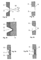
- the projections 3 according to the invention and the recesses 5 which resulting on the casting 6, are closer in Figures 3, 4 and 5 shown.
- the invention proposes that the projections 3 with an angle ⁇ , ⁇ between a center line 10 of the projections 3 and the outer edge of the projections 3 do not exceed 30 ° to manufacture.
- the notch factors on the recesses 5, which are due to the projections 3 arise on the casting 6 (Fig. 4, 5) are thereby advantageous reduced.
- the projections 3 can also be arranged at locations of the casting 6 be to which it is due to increased tensions during the Operation was previously not possible. Also a higher density of the protrusions 3 on the surface is conceivable.
- FIG. 3b of a projection 3 according to the invention is characterized in that the projection 3 over the surface of the Wax model 1 also protrudes in bulges 11 of the model form 9. This will be a length of approximately 1 to 2 mm.
- Such Arrangement is advantageous because there is a clearer demarcation of the edges of the Recess 5 on the finished casting 6 results.
- a thin cast skin or "Frayed" edges can be on the outside of the casting 6 at one Projection 3 according to Fig. 3a arise, which is an additional post-processing the cutouts 5 required.
- the embodiment according to FIG. 3b with protruding projections 3 also has the advantage that the projections 3 after removing the model shape 9 are visible from the outside, so that the resulting recesses 5 easier to find. The subsequent process steps are thus easier and more accurate to carry out.
- the recesses 5 from the outer surface of the Cast part 6 ago a recess 8 wholly or partially ground or eroded.
- This can generally be cylindrical (Fig. 4a) or conical (Fig. 4b) happen.
- the cast skin or "frayed edges" which by the embodiment of Fig. 3a are removed in this way.
- the notch factor at the recesses 5 is thereby reduced.
- This Recess 8 should have a depth of at least 0.1 mm. Usually a depth of 1 to 2 mm is selected.
- FIGS. 5a, b show which additional method steps are necessary are to process the recesses 5 on the finished casting 6.
- the recess 8 will be with a pin 7 which is round, conical or cylindrical and can also have different lengths.
- the pin 7 can in the casting 6 is soldered or welded or by another appropriate process.
- a pin 7 can be the length of the recess 8 correspond, but it can also be longer or shorter.
- the conical recess 8 is closed with a ball. To This ball is avoided by means of a resistance spot welding process to avoid long welding times to the contact surfaces of the recess welded. The ball can then be flush with the component surface be ground so that the remaining part of the recess 8 as a pin 7th crowded.
- Closing the cutouts 8 also reduces consumption the cooling air because it prevents it from escaping. Another advantage of closing is that there is local overheating of the edges of the recesses 5 is prevented. This can be when cleaning coated Blades occur, for example, through arc cleaning.
Landscapes
- Engineering & Computer Science (AREA)
- Mechanical Engineering (AREA)
- Molds, Cores, And Manufacturing Methods Thereof (AREA)
- Turbine Rotor Nozzle Sealing (AREA)
Abstract
Description
- Fig. 1
- ein Wachsmodell einer Turbinenschaufel mit einem Einsatz zeigt,
- Fig. 2
- einen Schnitt gemäss der Linie II - II in der Figur 1 zeigt,
- Fig. 3a,b
- zwei Ausführungsformen von erfindungsgemässen Vorsprüngen gemäss dem Ausschnitt III in der Figur 2 zeigen,
- Fig. 4a,b
- ein fertiges Gussteil, an welchem von der äusseren Oberfläche eine weitere Aussparung angebracht worden ist, darstellen und
- Fig. 5a,b
- die an den fertigen Gusstücken durch die erfindungsgemässen Vorsprünge entstandenen Aussparungen und deren Verschliessen durch Stifte darstellen.
- 1
- Wachsmodell einer Turbinenschaufel
- 2
- Keramischer Einsatz
- 3
- Vorsprung
- 4
- Wachs
- 5
- Aussparung
- 6
- Gussteil
- 7
- Stift
- 8
- Aussparung
- 9
- Modellform
- 10
- Mittellinie des Vorsprungs 3
- 11
- Ausbuchtung
- α
- Winkel zwischen Mittellinie 10 und Aussenkante des Vorsprungs 3
- β
- Winkel zwischen Mittellinie 10 und Aussenkante des Vorsprungs 3
Claims (15)
- Verfahren zur Herstellung eines Gussteils (6) einer thermischen Turbomaschine mit einem bekannten Gussverfahren, wobei das Gussteil (6) mittels einer keramische Gussform hergestellt wird, wobei diese keramische Gussform mittels eines Wachsmodells (1) und mittels eines sich im Wachsmodell (1) befindlichen, keramischen Einsatzes (2) hergestellt wird, und wobei das Wachsmodell (1) durch eine Modellform (9) und den sich in der Modellform (9) befindenden, keramischen Einsatz (2) hergestellt wird und wobei sich an der Aussenseite des keramischen Einsatzes (2) Vorsprünge (3) zur Einhaltung einer Wanddickentoleranz des Gussteils (6) befinden,
dadurch gekennzeichnet, dass
an dem Gussteil (6) Aussparungen (5) durch die Vorsprünge (3) des keramischen Einsatzes (2) hergestellt werden, wobei die Vorsprünge einen Winkel (α, β) zwischen der Mittellinie (10) und der Aussenkante der Vorsprünge (3) von kleiner 30° aufweisen. - Verfahren nach Anspruch 1,
dadurch gekennzeichnet, dass
an dem Gussteil (6) Aussparungen (5) durch die Vorsprünge (3) des keramischen Einsatzes (2) hergestellt werden, wobei die Vorsprünge (3) einen Winkel (α, β) zwischen der Mittellinie (10) und der Aussenkante der Vorsprünge (3) von kleiner 15° aufweisen. - Verfahren nach Anspruch 1 oder 2,
dadurch gekennzeichnet, dass
an dem Gussteil (6) Aussparungen (5) durch die Vorsprünge (3) des keramischen Einsatzes (2) hergestellt werden, wobei die Vorsprünge (3) an verschiedenen Seiten unterschiedliche Winkel (α, β) zwischen der Mittellinie (10) und der Aussenkante der Vorsprünge (3) aufweisen. - Verfahren nach Anspruch 1 oder 2,
dadurch gekennzeichnet, dass
an dem Gussteil (6) Aussparungen (5) durch die Vorsprünge (3) des keramischen Einsatzes (2) hergestellt werden, wobei die Vorsprünge (3) in die Modellform (9) während des Giessverfahrens hineinragen. - Verfahren nach Anspruch 3,
dadurch gekennzeichnet, dass
überstehendes Material, welches sich während des Giessverfahrens um die hervorragenden Vorsprünge (3) an der Oberfläche des Gussteils (6) gebildet hat, entfernt wird. - Verfahren nach einem der Ansprüche 1 bis 4,
dadurch gekennzeichnet, dass
die am Gussteil (6) durch die Vorsprünge (3) entstandenen Aussparungen (5) von der äusseren Seite des Gussteils (6) her teilweise in einer konischen oder zylindrischen Form ganz oder teilweise ausgeschliffen oder erodiert werden, so dass dort Aussparungen (8) entstehen. - Verfahren nach Anspruch 5,
dadurch gekennzeichnet, dass
in die Aussparungen (8) an der äusseren Seite des Gussteils (6) zylindrische, konische oder runde Stifte (7) angebracht, insbesondere gelötet oder geschweisst, werden und auf diese Art die Aussparungen (8) von der äusseren Seite des Gussteils (6) her verschlossen werden. - Modellform (9), enthaltend einen keramischer Einsatz (2), zum Gebrauch in einem Verfahren nach einem der Ansprüche 1 bis 7, mit sich an dem keramischen Einsatz (2) befindenden Vorsprüngen (3), wobei der keramische Einsatz (2) während des Giessverfahrens in der Modellform (9) angeordnet ist,
dadurch gekennzeichnet, dass
die Vorsprünge (3) des keramischen Einsatzes (2) einen Winkel (α, β) zwischen der Mittellinie (10) und der Aussenkante der Vorsprünge (3) von kleiner 30° aufweisen. - Modellform (9) nach Anspruch 8,
dadurch gekennzeichnet, dass
die Vorsprünge (3) des keramischen Einsatzes (2) einen Winkel (α, β) zwischen der Mittellinie (10) und der Aussenkante der Vorsprünge (3) von kleiner 15° aufweisen. - Modellform (9) nach Anspruch 8 oder 9,
dadurch gekennzeichnet, dass
die Winkel (α, β) an verschiedenen Seiten des Vorsprungs (3) unterschiedlich sind. - Modellform (9) nach Anspruch 8 oder 9,
dadurch gekennzeichnet, dass
die Vorsprünge (3) des keramischen Einsatzes (2) über die äussere Oberfläche des zu giessenden Gussteils (6) hinaus in Ausbuchtungen (11), welche in der Modellform (9) angeordnet sind, hineinragen. - Modellform (9) nach Anspruch 9,
dadurch gekennzeichnet, dass
die Ausbuchtungen (11), welche in der Modellform (9) angeordnet sind, die die Vorsprünge (3) aufnehmen, einen flachen Grund haben. - Keramischer Einsatz (2) zum Gebrauch in einem Verfahren nach einem der Ansprüche 1 bis 7 und zum Einsatz in eine Modellform (9) gemäss den Ansprüchen 8 bis 12, mit sich an dem keramischen Einsatz (2) befindenden Vorsprüngen (3),
dadurch gekennzeichnet, dass
die Vorsprünge (3) des keramischen Einsatzes (2) einen Winkel (α, β) zwischen der Mittellinie (10) und der Aussenkante der Vorsprünge (3) von kleiner 30° aufweisen. - Keramischer Einsatz (2) nach Anspruch 13,
dadurch gekennzeichnet, dass
die Vorsprünge (3) des keramischen Einsatzes (2) einen Winkel (α) zwischen der Mittellinie (10) und der Aussenkante der Vorsprünge (3) von kleiner 15° aufweisen. - Keramischer Einsatz (2) nach Anspruch 13 oder 14,
dadurch gekennzeichnet, dass
die Winkel (α, β) an verschiedenen Seiten des Vorsprungs (3) unterschiedlich sind.
Applications Claiming Priority (2)
| Application Number | Priority Date | Filing Date | Title |
|---|---|---|---|
| DE10060141 | 2000-12-04 | ||
| DE10060141A DE10060141A1 (de) | 2000-12-04 | 2000-12-04 | Verfahren zur Herstellung eines Gussteils, Modellform und keramischer Einsatz zum Gebrauch in diesem Verfahren |
Publications (3)
| Publication Number | Publication Date |
|---|---|
| EP1211001A2 true EP1211001A2 (de) | 2002-06-05 |
| EP1211001A3 EP1211001A3 (de) | 2003-07-16 |
| EP1211001B1 EP1211001B1 (de) | 2009-03-25 |
Family
ID=7665686
Family Applications (1)
| Application Number | Title | Priority Date | Filing Date |
|---|---|---|---|
| EP01128084A Expired - Lifetime EP1211001B1 (de) | 2000-12-04 | 2001-11-27 | Verfahren zur Herstellung eines Gussteils, Modellform und keramischer Einsatz zum Gebrauch in diesem Verfahren |
Country Status (4)
| Country | Link |
|---|---|
| US (1) | US6695036B2 (de) |
| EP (1) | EP1211001B1 (de) |
| JP (1) | JP2002178101A (de) |
| DE (2) | DE10060141A1 (de) |
Families Citing this family (3)
| Publication number | Priority date | Publication date | Assignee | Title |
|---|---|---|---|---|
| EP1331361B1 (de) * | 2002-01-17 | 2010-05-12 | Siemens Aktiengesellschaft | Gegossene Turbinenleitschaufel mit Hakensockel |
| GB201415726D0 (en) | 2014-09-05 | 2014-10-22 | Rolls Royce Plc | Casting of engine parts |
| KR101905993B1 (ko) * | 2016-10-31 | 2018-10-10 | 현대자동차주식회사 | 차량용 내장재 및 그 성형 방법 |
Citations (4)
| Publication number | Priority date | Publication date | Assignee | Title |
|---|---|---|---|---|
| US3690367A (en) | 1968-07-05 | 1972-09-12 | Anadite Inc | Apparatus for the restructuring of metals |
| US3763926A (en) | 1971-09-15 | 1973-10-09 | United Aircraft Corp | Apparatus for casting of directionally solidified articles |
| US5296308A (en) | 1992-08-10 | 1994-03-22 | Howmet Corporation | Investment casting using core with integral wall thickness control means |
| EP0749790A1 (de) | 1995-06-20 | 1996-12-27 | Abb Research Ltd. | Verfahren und Herstellung eines gerichtet erstarrten Giesskörpers und Vorrichtung zur Durchführung dieses Verfahrens |
Family Cites Families (5)
| Publication number | Priority date | Publication date | Assignee | Title |
|---|---|---|---|---|
| DE4042499C2 (de) * | 1990-12-21 | 1995-05-04 | Marianne Wieser | Gießform zum Herstellen von Formwerkstücken |
| US5291654A (en) * | 1993-03-29 | 1994-03-08 | United Technologies Corporation | Method for producing hollow investment castings |
| FR2711562B1 (fr) | 1993-10-29 | 1995-12-15 | Sintertech | Procédé de fabrication de pièces frittées conjuguées. |
| DE19636968B4 (de) * | 1996-09-12 | 2008-08-07 | Steinbeis Transferzentrum Arbeitsgemeinschaft Metallguss An Der Fachhochschule Aalen | Verfahren zur Herstellung von metallischen Prototypen |
| US6199746B1 (en) * | 1999-08-02 | 2001-03-13 | General Electric Company | Method for preparing superalloy castings using a metallurgically bonded tapered plug |
-
2000
- 2000-12-04 DE DE10060141A patent/DE10060141A1/de not_active Withdrawn
-
2001
- 2001-11-26 US US09/991,991 patent/US6695036B2/en not_active Expired - Lifetime
- 2001-11-27 DE DE50114786T patent/DE50114786D1/de not_active Expired - Lifetime
- 2001-11-27 EP EP01128084A patent/EP1211001B1/de not_active Expired - Lifetime
- 2001-12-04 JP JP2001370230A patent/JP2002178101A/ja active Pending
Patent Citations (4)
| Publication number | Priority date | Publication date | Assignee | Title |
|---|---|---|---|---|
| US3690367A (en) | 1968-07-05 | 1972-09-12 | Anadite Inc | Apparatus for the restructuring of metals |
| US3763926A (en) | 1971-09-15 | 1973-10-09 | United Aircraft Corp | Apparatus for casting of directionally solidified articles |
| US5296308A (en) | 1992-08-10 | 1994-03-22 | Howmet Corporation | Investment casting using core with integral wall thickness control means |
| EP0749790A1 (de) | 1995-06-20 | 1996-12-27 | Abb Research Ltd. | Verfahren und Herstellung eines gerichtet erstarrten Giesskörpers und Vorrichtung zur Durchführung dieses Verfahrens |
Also Published As
| Publication number | Publication date |
|---|---|
| US20020129924A1 (en) | 2002-09-19 |
| US6695036B2 (en) | 2004-02-24 |
| DE10060141A1 (de) | 2002-06-06 |
| EP1211001A3 (de) | 2003-07-16 |
| JP2002178101A (ja) | 2002-06-25 |
| DE50114786D1 (de) | 2009-05-07 |
| EP1211001B1 (de) | 2009-03-25 |
Similar Documents
| Publication | Publication Date | Title |
|---|---|---|
| DE69323817T2 (de) | Präzisionsgiessen unter Verwendung von Kern mit integrierter Wanddickenkontrollvorrichtung | |
| DE60034138T2 (de) | Mehrteilige kernanordnung für gegossene turbinenschaufel | |
| DE2932940C3 (de) | Luftgekühlte Hohlschaufel für Gasturbinen | |
| DE69826970T2 (de) | Linearreibschweissverfahren | |
| DE2831292C2 (de) | Verfahren zur Herstellung eines verlorenen Kerns zum Gießen einer Turbinenschaufel | |
| EP1155760A1 (de) | Verfahren zur Herstellung eines thermisch belasteten Gussteils | |
| DE69317690T2 (de) | Aufbau zur Herstellung eines Modelles aus hohlen Einzelteilen | |
| DE3312867A1 (de) | Verfahren und vorrichtung zur herstellung eines gegossenen metallgegenstandes | |
| EP1065026A1 (de) | Verfahren zur Herstellung oder zur Reparatur von Kühlkanälen in einstristallinen Komponenten von Gasturbinen | |
| DE69608389T2 (de) | Turbinenschaufel und Giessverfahren mit optimaler Wandstärkenkontrolle | |
| DE69704728T2 (de) | Vorrichtung und Kern zum Giessen von Zylinderblöcken der Bauart "closed deck" | |
| DE2309824A1 (de) | Verfahren zur herstellung einer hohlschaufel | |
| DE69508122T2 (de) | Verfahren zur Herstellung keramischer Giessmasken zum Giessen mit verlorenem Modell | |
| DE1195910B (de) | Verfahren zur Herstellung von gegossenen hohlen Turbinenschaufeln | |
| EP1193006A2 (de) | Verfahren zur Herstellung eines gekühlten Feingussteils | |
| EP2772325B1 (de) | Kühlmittelmantelkern sowie Verfahren zur Herstellung eines Zylinderkurbelgehäuses mit schmaler Stegbreite | |
| EP1211001B1 (de) | Verfahren zur Herstellung eines Gussteils, Modellform und keramischer Einsatz zum Gebrauch in diesem Verfahren | |
| EP2421666A1 (de) | Giessvorrichtung zum herstellen einer turbinenlaufschaufel einer gasturbine und turbinenlaufschaufel | |
| DE3104920C2 (de) | "Wachsmodell für die Feingießtechnik" | |
| DE2936481C2 (de) | Schaufel für ein Gasturbinentriebwerk | |
| DE102006050440A1 (de) | Verfahren zum Herstellen einer Leichtbau-Turbinenschaufel | |
| WO2009112400A1 (de) | Hohlgegossenes gussteil | |
| DE102004028426B4 (de) | Einsatzkern und Verfahren zur Herstellung eines Zylinders für einen Verbrennungsmotor mit dem Einsatzkern | |
| EP3538315B1 (de) | Verfahren zur herstellung eines hohlraums in einer schaufelplattform ; entsprechender schaufel | |
| DE19726111C1 (de) | Verfahren zur gießtechnischen Herstellung einer Turbomaschinenschaufel |
Legal Events
| Date | Code | Title | Description |
|---|---|---|---|
| PUAI | Public reference made under article 153(3) epc to a published international application that has entered the european phase |
Free format text: ORIGINAL CODE: 0009012 |
|
| AK | Designated contracting states |
Kind code of ref document: A2 Designated state(s): AT BE CH CY DE DK ES FI FR GB GR IE IT LI LU MC NL PT SE TR |
|
| AX | Request for extension of the european patent |
Free format text: AL;LT;LV;MK;RO;SI |
|
| RAP1 | Party data changed (applicant data changed or rights of an application transferred) |
Owner name: ALSTOM (SWITZERLAND) LTD |
|
| PUAL | Search report despatched |
Free format text: ORIGINAL CODE: 0009013 |
|
| AK | Designated contracting states |
Designated state(s): AT BE CH CY DE DK ES FI FR GB GR IE IT LI LU MC NL PT SE TR |
|
| AX | Request for extension of the european patent |
Extension state: AL LT LV MK RO SI |
|
| RAP1 | Party data changed (applicant data changed or rights of an application transferred) |
Owner name: ALSTOM TECHNOLOGY LTD |
|
| 17P | Request for examination filed |
Effective date: 20031206 |
|
| AKX | Designation fees paid |
Designated state(s): DE GB |
|
| 17Q | First examination report despatched |
Effective date: 20070201 |
|
| GRAP | Despatch of communication of intention to grant a patent |
Free format text: ORIGINAL CODE: EPIDOSNIGR1 |
|
| GRAS | Grant fee paid |
Free format text: ORIGINAL CODE: EPIDOSNIGR3 |
|
| RIN1 | Information on inventor provided before grant (corrected) |
Inventor name: HOFFS, ALEXANDER Inventor name: BEECK, ALEXANDER, DR. Inventor name: MUECKE, ROLAND Inventor name: RIAZANTSEV, SERGEJ Inventor name: BRANDL, HERBERT |
|
| GRAA | (expected) grant |
Free format text: ORIGINAL CODE: 0009210 |
|
| RIN1 | Information on inventor provided before grant (corrected) |
Inventor name: BRANDL, HERBERT Inventor name: HOFFS, ALEXANDER Inventor name: BEECK, ALEXANDER, DR. Inventor name: MUECKE, ROLAND Inventor name: RIAZANTSEV, SERGEJ |
|
| AK | Designated contracting states |
Kind code of ref document: B1 Designated state(s): DE GB |
|
| REG | Reference to a national code |
Ref country code: GB Ref legal event code: FG4D Free format text: NOT ENGLISH |
|
| REF | Corresponds to: |
Ref document number: 50114786 Country of ref document: DE Date of ref document: 20090507 Kind code of ref document: P |
|
| PLBE | No opposition filed within time limit |
Free format text: ORIGINAL CODE: 0009261 |
|
| STAA | Information on the status of an ep patent application or granted ep patent |
Free format text: STATUS: NO OPPOSITION FILED WITHIN TIME LIMIT |
|
| 26N | No opposition filed |
Effective date: 20091229 |
|
| REG | Reference to a national code |
Ref country code: DE Ref legal event code: R082 Ref document number: 50114786 Country of ref document: DE Representative=s name: ROESLER, UWE, DIPL.-PHYS.UNIV., DE Ref country code: DE Ref legal event code: R081 Ref document number: 50114786 Country of ref document: DE Owner name: GENERAL ELECTRIC TECHNOLOGY GMBH, CH Free format text: FORMER OWNER: ALSTOM TECHNOLOGY LTD., BADEN, CH Ref country code: DE Ref legal event code: R081 Ref document number: 50114786 Country of ref document: DE Owner name: ANSALDO ENERGIA SWITZERLAND AG, CH Free format text: FORMER OWNER: ALSTOM TECHNOLOGY LTD., BADEN, CH |
|
| PGFP | Annual fee paid to national office [announced via postgrant information from national office to epo] |
Ref country code: DE Payment date: 20161121 Year of fee payment: 16 Ref country code: GB Payment date: 20161122 Year of fee payment: 16 |
|
| REG | Reference to a national code |
Ref country code: GB Ref legal event code: 732E Free format text: REGISTERED BETWEEN 20170727 AND 20170802 |
|
| REG | Reference to a national code |
Ref country code: DE Ref legal event code: R082 Ref document number: 50114786 Country of ref document: DE Representative=s name: ROESLER, UWE, DIPL.-PHYS.UNIV., DE Ref country code: DE Ref legal event code: R081 Ref document number: 50114786 Country of ref document: DE Owner name: ANSALDO ENERGIA SWITZERLAND AG, CH Free format text: FORMER OWNER: GENERAL ELECTRIC TECHNOLOGY GMBH, BADEN, CH |
|
| REG | Reference to a national code |
Ref country code: DE Ref legal event code: R119 Ref document number: 50114786 Country of ref document: DE |
|
| GBPC | Gb: european patent ceased through non-payment of renewal fee |
Effective date: 20171127 |
|
| PG25 | Lapsed in a contracting state [announced via postgrant information from national office to epo] |
Ref country code: DE Free format text: LAPSE BECAUSE OF NON-PAYMENT OF DUE FEES Effective date: 20180602 |
|
| PG25 | Lapsed in a contracting state [announced via postgrant information from national office to epo] |
Ref country code: GB Free format text: LAPSE BECAUSE OF NON-PAYMENT OF DUE FEES Effective date: 20171127 |