EP1209441A1 - Three-dimensional shape-measuring instrument with laser scanner - Google Patents
Three-dimensional shape-measuring instrument with laser scanner Download PDFInfo
- Publication number
- EP1209441A1 EP1209441A1 EP01403013A EP01403013A EP1209441A1 EP 1209441 A1 EP1209441 A1 EP 1209441A1 EP 01403013 A EP01403013 A EP 01403013A EP 01403013 A EP01403013 A EP 01403013A EP 1209441 A1 EP1209441 A1 EP 1209441A1
- Authority
- EP
- European Patent Office
- Prior art keywords
- axis
- lifting device
- rotation
- dimensional lifting
- laser beam
- Prior art date
- Legal status (The legal status is an assumption and is not a legal conclusion. Google has not performed a legal analysis and makes no representation as to the accuracy of the status listed.)
- Granted
Links
Images


Classifications
-
- G—PHYSICS
- G01—MEASURING; TESTING
- G01B—MEASURING LENGTH, THICKNESS OR SIMILAR LINEAR DIMENSIONS; MEASURING ANGLES; MEASURING AREAS; MEASURING IRREGULARITIES OF SURFACES OR CONTOURS
- G01B11/00—Measuring arrangements characterised by the use of optical techniques
- G01B11/002—Measuring arrangements characterised by the use of optical techniques for measuring two or more coordinates
-
- G—PHYSICS
- G01—MEASURING; TESTING
- G01B—MEASURING LENGTH, THICKNESS OR SIMILAR LINEAR DIMENSIONS; MEASURING ANGLES; MEASURING AREAS; MEASURING IRREGULARITIES OF SURFACES OR CONTOURS
- G01B11/00—Measuring arrangements characterised by the use of optical techniques
- G01B11/24—Measuring arrangements characterised by the use of optical techniques for measuring contours or curvatures
-
- G—PHYSICS
- G01—MEASURING; TESTING
- G01C—MEASURING DISTANCES, LEVELS OR BEARINGS; SURVEYING; NAVIGATION; GYROSCOPIC INSTRUMENTS; PHOTOGRAMMETRY OR VIDEOGRAMMETRY
- G01C11/00—Photogrammetry or videogrammetry, e.g. stereogrammetry; Photographic surveying
-
- G—PHYSICS
- G01—MEASURING; TESTING
- G01S—RADIO DIRECTION-FINDING; RADIO NAVIGATION; DETERMINING DISTANCE OR VELOCITY BY USE OF RADIO WAVES; LOCATING OR PRESENCE-DETECTING BY USE OF THE REFLECTION OR RERADIATION OF RADIO WAVES; ANALOGOUS ARRANGEMENTS USING OTHER WAVES
- G01S17/00—Systems using the reflection or reradiation of electromagnetic waves other than radio waves, e.g. lidar systems
- G01S17/02—Systems using the reflection of electromagnetic waves other than radio waves
- G01S17/06—Systems determining position data of a target
- G01S17/42—Simultaneous measurement of distance and other co-ordinates
-
- G—PHYSICS
- G01—MEASURING; TESTING
- G01S—RADIO DIRECTION-FINDING; RADIO NAVIGATION; DETERMINING DISTANCE OR VELOCITY BY USE OF RADIO WAVES; LOCATING OR PRESENCE-DETECTING BY USE OF THE REFLECTION OR RERADIATION OF RADIO WAVES; ANALOGOUS ARRANGEMENTS USING OTHER WAVES
- G01S7/00—Details of systems according to groups G01S13/00, G01S15/00, G01S17/00
- G01S7/48—Details of systems according to groups G01S13/00, G01S15/00, G01S17/00 of systems according to group G01S17/00
- G01S7/481—Constructional features, e.g. arrangements of optical elements
- G01S7/4817—Constructional features, e.g. arrangements of optical elements relating to scanning
-
- G—PHYSICS
- G02—OPTICS
- G02B—OPTICAL ELEMENTS, SYSTEMS OR APPARATUS
- G02B26/00—Optical devices or arrangements for the control of light using movable or deformable optical elements
- G02B26/08—Optical devices or arrangements for the control of light using movable or deformable optical elements for controlling the direction of light
- G02B26/10—Scanning systems
- G02B26/101—Scanning systems with both horizontal and vertical deflecting means, e.g. raster or XY scanners
-
- G—PHYSICS
- G01—MEASURING; TESTING
- G01S—RADIO DIRECTION-FINDING; RADIO NAVIGATION; DETERMINING DISTANCE OR VELOCITY BY USE OF RADIO WAVES; LOCATING OR PRESENCE-DETECTING BY USE OF THE REFLECTION OR RERADIATION OF RADIO WAVES; ANALOGOUS ARRANGEMENTS USING OTHER WAVES
- G01S17/00—Systems using the reflection or reradiation of electromagnetic waves other than radio waves, e.g. lidar systems
- G01S17/88—Lidar systems specially adapted for specific applications
- G01S17/89—Lidar systems specially adapted for specific applications for mapping or imaging
Definitions
- the present invention relates to a lifting device three-dimensional scene.
- the present invention relates to a device for three-dimensional bearing, comprising a laser transmitter, means of scanning along first and second axes of rotation to scan the scene at using a laser beam emitted by the laser transmitter, a photosensitive receiver an image of a spot created by the laser beam on the scene, means of focusing of the laser beam backscattered by the scene towards the receiver photosensitive, from the first means of measuring the orientation of the beam to the output of the scanning means, and second means for measuring the distance between the device and the spot by laser telemetry, including a blade separator of the beams emitted and backscattered by the scene.
- Such a device comprises a laser pulse emitter, scanning means comprising two free galvanometric mirrors rotating around two respective axes orthogonal, and encoders to direct the laser beam and determine the orientation of it, depending on the positions of the two mirrors galvanometer.
- scanning means comprising two free galvanometric mirrors rotating around two respective axes orthogonal, and encoders to direct the laser beam and determine the orientation of it, depending on the positions of the two mirrors galvanometer.
- it includes an optical beam splitter by the pulse emitter and the beam backscattered by the scene, which allows measure the distance between the device and the spot created by the laser beam on the scene, by measuring the "flight time" of the laser pulse.
- the device also includes means for measuring the instant of emission of the laser beam and of the means for measuring the instant of reception by a photosensitive receiver of the beam backscattered by the scene.
- a pulse emitted by the laser transmitter is partially reflected by the separator towards the two galvanometric mirrors to create a spot on the stage.
- Part of the impulse received by the scene is then backscattered to the two galvanometric mirrors, then crosses the separator to be received by a telescope focusing its energy on the receiver photosensitive.
- the device When the device applies to measurements spanning a large range of distances, such as conventionally from 1 to 100 meters, the energy of the backscattered beam being inversely proportional to the square of the distance from the spot to the device, the measurement made by the receiver photosensitive can suffer from large beam energy dynamics received by him.
- the invention aims to remedy this drawback by creating a device able to limit and then take into account the energy dynamics of backscattered beams received by the photosensitive receiver.
- the invention therefore relates to a lifting device three-dimensional scene, comprising a laser transmitter, means for scanning along first and second axes of rotation to scan the scene at using a laser beam emitted by the laser transmitter, a photosensitive receiver an image of a spot created by the laser beam on the scene, means of focusing of the laser beam backscattered by the scene towards the receiver photosensitive, from the first means of measuring the orientation of the beam to the output of the scanning means, and second means for measuring the distance between the device and the spot by laser telemetry, said second means measuring device comprising a separating plate for the emitted and backscattered beams by the scene, characterized in that the focusing means comprise a converging optical system associated with a diverging optical system increasing the focal length of the converging optical system forming thus a telephoto lens, and in that the scanning means comprise at least a mirror placed on the path of the emitted and backscattered laser beams, between the focusing means and the scene.
- the device according to the invention makes it possible to compensate for the dynamic of the energy of the backscattered beam received by the photosensitive receiver, in providing focusing means having a large focal length and a low focal length footprint.
- the focal length of the focusing means increases the size of the spot image created on the receiver photosensitive, so that it completely covers it, even when the spot is very far from the device.
- the size of its image at the photosensitive receptor increases inversely proportional to the square of the distance separating the spot from the device, as beam energy.
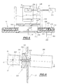
- a lifting device 2 three-dimensional of a scene 4 materialized by a pottery for example, has a housing 6 in which is a window 8 transparent to light beams.
- This housing 6 has two parts.
- a first part, in which the window 8 is located, comprises optical systems and constitutes the opto-mechanical part 10 of the device 2.
- a second part, located below the first part, contains electronic systems, the essential elements of which will be described with reference to FIGS. 8 and 9 and constitutes the electronic part 12 of the device 2.
- This electronic part includes calculation and storage of sufficient data to implement methods of raising, representing, modifying or activating the opto-mechanical part 10, classics.
- the electronic part 12 includes an architecture of on-board microcomputer including a backplane capable of accommodating electronic cards supporting different formats of transmission bus data, such as PCI, ISA buses.
- It also has a compact microcomputer card equipped with a static hard disk, and piloting cards of different elements opto-mechanical part 10 and electronic part 12, which will be described thereafter.
- the electronic part 12 is connected to a device for external control (not shown), such as a laptop or electronic personal organizer, using an ethernet link.
- This platform 14 is enslaved in angular position around a vertical axis 16 cutting it into sound center by a servo device which will be described with reference to the figure 3, thus allowing a scanning of the scene 4 by the device 2.
- the laser transmitter 20, the autofocus system 22, the prismatic blade 24 and the assembly constituted by the separating blade 32 and the semi-reflecting patch 34, are arranged so that the axes 16, 26 and 36 are rigorously coplanar.
- a laser beam emitted by the laser emitter 20 on the axis 26 reaches the prismatic plate 24 after having passed through the focusing assembly 22 automatic. It enters the prismatic plate 24 through a first flat surface 24a of separation, perpendicular to the axis 26.
- This reflected part of the laser beam again reaches the first planar surface 24a at a point of contact between this first planar surface 24a of the prismatic plate 24 and a first end of the optical fiber 28.
- the other end of the optical fiber 28 is connected to a photosensitive receiver 29, determining an instant T 1 of reception of the part of the laser beam reflected by the prismatic plate 24. This instant T 1 is considered thereafter as the instant emission of the laser beam.
- the laser beam After passing through the prismatic plate 24, the laser beam reaches the semi-reflective patch 34 in the center thereof.
- Part of the laser beam is then reflected along the optical axis 36 towards the spherical mirror 38, while the other part of the laser beam is completely absorbed by the light trap 30 after passing through the blade divider 32.
- the laser beam reflected by the separating plate 32 then reaches the spherical mirror 38 at a point J predetermined by off-axis positioning of the spherical mirror on the mount 19.
- the spherical mirror 38 is positioned relative to the mount 19 and to the platform 14, so that the laser beam, after being reflected on the spherical mirror at point J, follows a path included in the plane containing the axes 16, 26 and 36, and meets the galvanometric mirror 42 at point 0 intersection of axes 16 and 44, axis 44 also being orthogonal to the plane in which moves the laser beam.
- point 0 is located in the center of the reflecting surface of the galvanometric mirror 42.
- the laser beam is then reflected by the galvanometric mirror 42, then creates a light spot 52 on stage 4, after having crossed window 8.
- part of it follows substantially the same path as that described above, in opposite direction, up to the assembly constituted by the separating blade 32 and the patch semi-reflective 34, and crosses this assembly along the axis 36, in the direction of the photosensitive receiver 46.
- the laser beam Before reaching the photosensitive receiver 46, the laser beam, having crossed the separating blade 32, passes through the divergent lens 50 and then the interference filter 48.
- the photosensitive receiver 46 determines the instant T 2 of reception of the laser beam backscattered by the scene.
- the calculation of the distance separating the spot 52 from the point 0 as a function of the instants T 1 and T 2 is considered to be known per se.
- the function of the semi-reflecting patch 34 is to direct a part of the laser beam emitted towards the spherical mirror 38 along the optical axis 36. But it also has the function of modifying the energy dynamics of a part of the laser beam backscattered by scene 4 and received by the receiver photosensitive 46.
- the energy of the laser beam backscattered by scene 4 is important, but the diameter of this laser beam passing through the separating plate 32 is less than that of the patch semi-reflective 34.
- the separating blade 32 is in general with a fully reflective central shutter, which has the effect of preventing the measurement of the distance from the spot 52 in this case.
- the separating blade is provided with a pad such as the semi-reflecting patch 34, the part of the beam which crosses the separator plate 32 passes entirely through the semi-reflecting patch 34 and an attenuated part of this beam reaches the photosensitive receiver 46.
- the energy of the laser beam backscattered by scene 4 is weak, since it varies according to inverse of the square of the distance but the diameter of this laser beam and crossing the separating blade 32 is more important and beyond a distance predetermined, it becomes larger than that of the semi-reflecting patch 34.
- part of the beam energy is entirely transmitted by the separating plate 32 to the photosensitive receiver 46, in periphery of the semi-reflecting patch 34. This part entirely transmitted is all the more important as the spot is further from the device and therefore the energy of the backscattered laser beam is low.
- the laser transmitter 20 is micro-laser with a peak power equal to 278 W.
- the spherical mirror 38 has a diameter such that the optical receiving diameter of the device is 40 mm.
- the semi-reflecting patch 34 has a diameter of 6 mm and a reflecting power of 0.5.
- the Albedo of the receiving surface of the photosensitive receiver 46 which represents its backscatter coefficient, is 0.01.
- the first column represents the distance between the spot 52 of the device 2.
- the second column represents the power of the laser beam backscattered by scene 4 at device 2 in the opening defined by the 40 mm optical diameter: we notice that this power is inversely proportional to the distance from the first column.
- the third column represents the power of the part of the beam backscattered onto the photosensitive receiver 46 and transmitted entirely by the separating plate 32, on the periphery of the semi-reflecting patch 34.
- the fourth column represents the power of the part of the beam backscattered onto the photosensitive receiver 46 and partially transmitted by the semi-reflecting patch 34.
- the fifth column of the results table represents the sum of the two previous columns, i.e. the total power received by the photosensitive receiver 46.
- the dynamics of beam received by the photosensitive receiver 46 is less than 3: it varies from 0.08 ⁇ W to 0.23 ⁇ W for distances varying from 1 to 90 meters.
- the section 20p of the wave surface by a plane perpendicular to the direction of displacement of this pulse is circular.
- the prismatic blade 24 introducing a deformation of the wave surface of the pulse by astigmatism, its section 24p becomes elliptical between the prismatic blade 24 and the separator blade 32.
- a reflection on the separating plate 32 does not introduce astigmatism, the section 32pa of the wave surface of the laser pulse between this blade divider 32 and the spherical mirror 38, is always elliptical.
- the spherical mirror 38 disposed off axis with respect to the direction incident of the laser pulse, also introduces deformation by astigmatism of the wave surface of the laser pulse, when reflecting this last on the spherical mirror 38. So, the section 38pa of this wave surface becomes circular again between the spherical mirror 38 and the galvanometric mirror 42.
- the galvanometric mirror 42 does not introduce any deformation by astigmatism of the wave surface of the laser pulses, this reaches the scene 4, creating spot 52 which is circular.
- one of the functions of the spherical mirror 38 off axis is to compensate for the astigmatism introduced by the separating blade 32, when the laser pulse passes through it, as shown in Figure 3.
- the laser pulse backscattered by scene 4 has a surface wave whose section 4p by a plane perpendicular to the direction of displacement of the pulse is circular between scene 4 and the mirror galvanometric 42.
- this section 42p is always circular before reaching the spherical mirror 38.
- the spherical mirror 38 disposed off-axis with respect to the incident direction of the laser pulse, introduces an astigmatism of the pulse wave surface, so that after reflection on the latter and before reaching the separating blade 32, section 38pr of the wave surface of the laser pulse becomes elliptical.
- the separating blade 32 introduces astigmatism when the laser pulse passes through it, compensated by that of the spherical mirror 38, so that the section 32pr of the wave surface of this pulse becomes circular again before reaching the divergent lens 50.
- the divergent lens 50 and the interference filter 48 do not introduce deformation by astigmatism of the wave surface of the pulse, which has as a consequence that the image of the spot 52 at the photosensitive receiver 46 is circular.
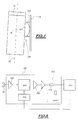
- the assembly 22 for automatic focusing of the device 2 as well as means for fixing the latter to the laser transmitter 20 are shown in the figure 4.
- the automatic focusing assembly 22 has symmetry axial around the vertical axis 16. It has two diverging lenses 60 and 62 fixed, centered on the axis 16, and a converging lens 64, also centered on the axis 16 and being able to move in translation along this axis.
- the two divergent lenses 60 and 62 are arranged in a first tubular mount 66.
- a first part 68 of small section of this mount 66 carries to its free end the divergent lens 60.
- the first cylindrical part 68 of the frame is connected to a second part 70 of larger section, by a transition zone 71 of frustoconical shape.
- the divergent lens 62 is mounted in this second part 70.
- a third part 72 forming a flange is integral with the second cylindrical part 70 at the end thereof opposite the first part 68.
- the mount 66 is mounted in a barrel 74 which has a bore end 76 surrounding the first part of small section 68 of the frame 66 and in which is slidably mounted a sleeve 78 supporting the lens convergent 64.
- the barrel 74 further comprises a bore of larger diameter 80, whose section corresponds to that of the second part 70 of section more important of the mount 66.
- the crown 86 is interposed between the collar 82 and the flange 72 and allows the setting in axial position of the mount 66 carrying the divergent lenses 60.62.
- Three screws 90 for locking the mount 66 arranged at 120 ° are disposed in axial holes 92 formed in the flange 72, extend to inside the crown 86 and are engaged in tapped holes 94 formed in the collar 82 of the barrel 74.
- an axial recess 94 is provided for fixing the laser transmitter 20.
- a base 96 with a diameter smaller than that of the recess 94 and to which the laser emitter 20 is fixed by three screws 98 arranged at 120 °.
- the base 96 is in turn fixed in the bottom of the recess 94 to using three screws 100 with flat heads arranged at 120 ° and engaged in holes axial 102 of larger diameter formed in the base 96 and allowing the radial adjustment of the position of the base and therefore of the laser transmitter 20 relative to the emission axis 16 of the device 2.
- the screws 100 are screwed into the flange 72.
- the recess 94 is delimited by a peripheral rim 104 in which are arranged three screws 106 for radially adjusting the laser transmitter 20.
- the screws 106 arranged at 120 ° each have for example, a knurled head 108 and one end in contact with the lateral surface 110 of the base 96.
- the barrel 74 is surrounded by a magnetic core 112 in which it is for example force fitted.
- the magnetic core 112 is generally cylindrical in shape and is coaxial with the barrel 74 and the mounts 66 and 78 respectively carrying the diverging lenses 60 and 62 and the converging lens 60.
- the magnetic core 112 is in contact by one of its faces with the collar 82 of barrel 74.
- annular groove 114 In the face of the magnetic core 112 opposite the flange 82 is formed an annular groove 114 defining a central projection 116 around which is arranged a coil 118 for actuating a membrane 120 by via a skirt 122 fixed by one of its ends to the membrane 120.
- the flexible membrane 120 is fixed at its periphery to the core magnetic 112 in a conventional manner. It has a hole in the center circular in which the sleeve 78 is engaged and fixed.
- the coil 118 is supplied by a current generator 124 of which the input is connected to the output of a comparator 126 between a generated signal by a PSD type photodiode 128, illuminated by a light beam coming from a light-emitting diode 130 on the path of which is placed the free end of the sleeve 78 carrying the converging lens 64, and a signal corresponding to the distance from spot 52 lighting up scene 4.
- the scanning means represented in FIG. 5 include the galvanometric mirror 42 associated with position control means around orthogonal axes 16 and 44, intersecting at point 0.
- the means for controlling the position of the mirror 42 around the axis vertical 16 allow a sweep in bearing of scene 4 and include a stepper motor 200 associated with a reduction gear 202, arranged under a crown fixed 204 on the periphery thereof.
- Reducer 202 controls rotation around a vertical axis of a pinion 206 passing through the fixed ring 204.
- the pinion 206 drives a movable crown 208 in rotation around the vertical axis 16, by means of a toothed belt 210 bonded to the crown mobile 208.
- the rotation of the movable crown 208 relative to the fixed crown 204 is ensured by a thin ball bearing 212, on a rod, arranged in a groove 213 formed on the periphery of the movable crown 208.
- movable crown 208 On the movable crown 208 are arranged two vertical plates such as plate 15, as well as a plate 223 fixed on these vertical plates.
- the platform 14, described with reference to FIG. 1, includes this plate 223 and the movable crown 208.
- Measuring the rotational displacement around axis 16 of the platform 14 is obtained by means of an optical encoder 214 integral with the crown fixed 204 by means of a fixing ring 216.
- the encoder 214 is an encoder incremental annular, of classical type.
- a cylindrical rim 220 delimiting the axial opening 18 of the plate 223, secured to the movable crown 208.
- the optical encoder 214 is provided with a part mobile 222 blocked on the flange 220 of the plate 223 by fixing screws (not shown). This allows the incremental measurement of the bearing rotation of platform 14.
- the means for controlling the position of the mirror 42 around the axis horizontal 44 allow an elevation scan of scene 4 and include an arm 224 connecting the galvanometric mirror 42 to a scanner galvanometric 226, of conventional type.
- the transmission arm 224 is fixed on the plate 15 by means of first means 228 for adjusting the axis of rotation 44 and allows the transmission around the axis to the mirror 42 44, controlled by the galvanometric scanner 226.
- the galvanometric mirror 42 is both slaved in position around the horizontal axis 44 by means of the galvanometric scanner 226, and slaved in position around the vertical axis 16, by means of the motor 200.
- the frame 19 is fixed to the plate 15, by through second means 229 for adjusting the optical axis 36.
- the first adjustment means 228 shown in FIG. 6 include a cradle 230 formed of a vertical crown portion whose center is positioned on the vertical axis 16, at point 0 located in the center of the mirror galvanometric 42.
- the cradle 230 slides in rotation on a cradle support 232 of the same radius with hollow axis, around a horizontal axis 233, perpendicular to axis 16 and axis 44, parallel to plate 15 and passing through 0.
- the support for cradle 232 is fixed to plate 15.
- the transmission arm 224 is mounted, free to rotate around its axis, inside a sleeve 233 secured to the cradle 230.
- the rotation of the cradle 230 around the horizontal axis 223 in the cradle support 232 causes rotation around this same axis of the assembly constituted by the galvanometric mirror 42, the sleeve 233, the arm 224 and the galvanometric scanner 226, mounted on this cradle 230.
- the second adjustment means 229 shown in top view at FIG. 7 comprises a cradle 234 formed by a portion of the crown horizontal, the center of which is positioned on the vertical axis 16.
- the cradle 234 slides in rotation on a cradle support 236 of same radius, around an axis perpendicular to axis 44 and in the plane containing the vertical axis 16.
- This cradle support 236 is fixed to the plate 15.
- the adjustment means 228 and 229 allow the adjustment of the axis optic 36 and the axis 44 of rotation of the galvanometric mirror 42, by compensation for construction imperfections, such as for example fitting imprecise of the galvanometric mirror 42 on the arm 224 intended to drive it in rotation.
- the scanning means can provide scanning strictly plan.
- the photosensitive receiver 46 is associated with means 300 for reducing the dynamics of the signal supplied at the output of this photosensitive receiver 46. These means 300 are integrated into the part electronics 12 of figure 1.
- the photosensitive receiver 46 comprises a photodiode with avalanche providing a current output whose intensity depends directly on the energy of the laser beam it received.
- the means 300 for reducing the dynamics comprise a transimpedance amplifier 302 supplying an electrical signal as an output the voltage is proportional to the intensity of the current supplied as input by the avalanche photodiode. This electrical signal is transmitted to a programmable voltage 304, conventionally associated with means of programming 306.
- the means 300 for reducing the dynamics also include two fixed gain amplifiers 308 arranged in series, at the output of the attenuator 304.
- the number of amplifiers 308 can be different from two.
- the electrical signal output from the fixed gain amplifiers 308 supplies an impedance matching circuit 310, of the conventional type.
- this impedance matching circuit 310 includes two resistors 312, of 50 Ohms each.
- the electrical signal supplied at the output of this adaptation circuit impedance 310 supplies means 314 for measuring the "flight time" of the laser beam implemented on an integrated circuit.
- These measurement means 314 are of the classic type. They are for example of the type described in the French patent n ° 94 11 847 of the French Atomic Energy Commission. They are particularly adapted to provide the programming means with a numerical value of the energy of the signal transmitted to them by the impedance matching circuit 310.
- the programming means 306 determine and regulate the gain of the attenuator 304 to a value inversely proportional to this value digital supplied by the "flight time” measuring means 314, to supply at the output of the attenuator 304, a signal whose voltage is constant whatever or the energy of the laser beam received by photodiode 46.
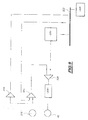
- a temperature probe 316 of the type conventional is arranged in the vicinity of photodiode 46.
- the voltage corresponding to the temperature measured by this probe 316 is transmitted to a conventional analog-to-digital converter 318, for transmitting a numerical value of this temperature to a 320 computer via a data transmission bus 322.
- the computer 320 transmits via the bus 322, a multiplier coefficient to a digital to analog converter multiplier 324 and a digital setpoint value to a converter digital-analog 326.
- the multiplier coefficient depends on the nature of the temperature 316 and the nature of photodiode 46, but is independent of the temperature measured by probe 316, while the numerical value of setpoint supplied to converter 326 depends on the temperature measured by the probe 316 and corresponds to a predetermined gain value of the photodiode 46, at a given temperature.
- This gain value is provided, for example, by a data table conventionally accessible by the computer 320.
- the digital-analog converter multiplier 324 has a reference input and a digital input. he receives, on its reference input, the voltage corresponding to the temperature measured by probe 316 and on its other digital input, the coefficient multiplier.
- a summing amplifier 328 receives this input voltage as an input. correction as well as a setpoint voltage supplied at the converter output digital-analog 326 and therefore directly related to the digital value of setpoint provided by the computer 320.
- This summing amplifier 328 supplies a voltage of command equal to the sum of the correction voltage and the voltage of setpoint. This voltage value keeps a constant gain in photodiode 46, regardless of temperature variations.
- control voltage is then applied to means 330 supply of photodiode 46, of conventional type, for adjusting the voltage of polarization of the photodiode 46 in accordance with the control voltage supplied by summing amplifier 328.
- spherical coordinates of all the points raised include the distance between the center O of the mirror galvanometric 42 spot 52, an angle measuring the bearing orientation of the laser beam at the exit of the scanning means and an angle measuring the orientation in site of this same laser beam.
- the scanning means are piloted 14,42,200,202,204,206,210,212,224,226, as well as the transmitter 20, so that the spot 52 created on stage 4 by the laser beam successively designates at minus part of the points of the selected subset corresponding to said area of interest.
- This area of interest consists of a set of points which are not not necessarily joined.
- the invention illustrated in the example described previously, creates a three-dimensional lifting device capable of performing measurements over a wide range of distance, compensating for the dynamic effect due to beam energy backscattered inversely proportional to the square of the distance between the spot 52 and the device 2, by a large focal length of the focusing means, while with a reduced bulk.
- a second advantage of the device described above is compensate using a spherical mirror arranged off-axis relative to the laser beam emitted and backscattered, the deformations of the wave surface of the beam caused by the separating plate 32, so that the image of spot 52 at level of the photosensitive receiver 46 is circular.
- Another advantage of the device described above is compensate for the deformations of the wave surface of the beam caused by the spherical mirror 38, on the outward path of the laser beam, between the laser emitter 20 and scene 4, using a prismatic blade 24 disposed between the laser transmitter 20 and the separating blade 32.
- Another advantage of the device described above is allow, thanks to a semi-reflecting patch placed on the blade separator 32, to make measurements, even when the spot is very close to the three-dimensional lifting device.
- Another advantage of the device described above is compensate for the significant dynamic range of the laser beams backscattered by the scene 4, linked to the broadcast indicator of said scene 4, by means of reduction of the dynamic range of the signal output from the photosensitive receiver 46.
- Another advantage of the device described above is to allow a sweep in a field of up to 360 °, while allowing passage of electrical connections between the electronic part and the opto-mechanical part of the device, by means of scanning comprising a platform pierced with an axial opening.
- Another advantage of the device described above is to allow a plan scan of scene 4, and therefore to avoid distortions of a whole of points noted on scene 4, by means of means adjustment servo in position of the galvanometric mirror 42 and the means of adjustment of the laser beam reception axis.
- Another advantage of the device described above is to provide good spatial resolution of the measurement on the target, thanks to a set of automatic focusing of the laser beam emitted by the transmitter 20.
- Another advantage of the device described above is implement a method for designating, in the reference frame of the device 2, an area of interest on scene 4, by means of the laser beam, this area of interest not necessarily accessible by an operator or easily materializable.
- This process can be applied for example to designate the route a cut to be made on a pipe.
Abstract
Description
La présente invention concerne un dispositif de relèvement tridimensionnel d'une scène.The present invention relates to a lifting device three-dimensional scene.
Plus particulièrement, la présente invention concerne un dispositif de relèvement tridimensionnel, comprenant un émetteur laser, des moyens de balayage selon des premier et second axes de rotation pour balayer la scène à l'aide d'un faisceau laser émis par l'émetteur laser, un récepteur photosensible d'une image d'un spot créé par le faisceau laser sur la scène, des moyens de focalisation du faisceau laser rétrodiffusé par la scène vers le récepteur photosensible, des premiers moyens de mesure de l'orientation du faisceau à la sortie des moyens de balayage, et des seconds moyens de mesure de la distance entre le dispositif et le spot par télémétrie laser, comprenant une lame séparatrice des faisceaux émis et rétrodiffusé par la scène.More particularly, the present invention relates to a device for three-dimensional bearing, comprising a laser transmitter, means of scanning along first and second axes of rotation to scan the scene at using a laser beam emitted by the laser transmitter, a photosensitive receiver an image of a spot created by the laser beam on the scene, means of focusing of the laser beam backscattered by the scene towards the receiver photosensitive, from the first means of measuring the orientation of the beam to the output of the scanning means, and second means for measuring the distance between the device and the spot by laser telemetry, including a blade separator of the beams emitted and backscattered by the scene.
Un tel dispositif est décrit dans le document US 5 988 862 A. Il comporte un émetteur d'impulsions laser, des moyens de balayage comportant deux miroirs galvanométriques libres en rotation autour de deux axes respectifs orthogonaux, et des codeurs pour diriger le faisceau laser et déterminer l'orientation de celui-ci, en fonction des positions des deux miroirs galvanométriques. De plus, il comporte un séparateur optique du faisceau émis par l'émetteur d'impulsions et du faisceau rétrodiffusé par la scène, ce qui permet d'effectuer une mesure de la distance entre le dispositif et le spot créé par le faisceau laser sur la scène, par mesure du " temps de vol " de l'impulsion laser. Pour ce faire, le dispositif comporte également des moyens de mesure de l'instant d'émission du faisceau laser et des moyens de mesure de l'instant de réception par un récepteur photosensible du faisceau rétrodiffusé par la scène.Such a device is described in document US 5,988,862 A. It comprises a laser pulse emitter, scanning means comprising two free galvanometric mirrors rotating around two respective axes orthogonal, and encoders to direct the laser beam and determine the orientation of it, depending on the positions of the two mirrors galvanometer. In addition, it includes an optical beam splitter by the pulse emitter and the beam backscattered by the scene, which allows measure the distance between the device and the spot created by the laser beam on the scene, by measuring the "flight time" of the laser pulse. To do this, the device also includes means for measuring the instant of emission of the laser beam and of the means for measuring the instant of reception by a photosensitive receiver of the beam backscattered by the scene.
Ainsi, une impulsion émise par l'émetteur laser est partiellement réfléchie par le séparateur vers les deux miroirs galvanométriques pour créer un spot sur la scène. Une partie de l'impulsion reçue par la scène est ensuite rétrodiffusée vers les deux miroirs galvanométriques, puis traverse le séparateur pour être reçue par un télescope focalisant son énergie sur le récepteur photosensible.So, a pulse emitted by the laser transmitter is partially reflected by the separator towards the two galvanometric mirrors to create a spot on the stage. Part of the impulse received by the scene is then backscattered to the two galvanometric mirrors, then crosses the separator to be received by a telescope focusing its energy on the receiver photosensitive.
Lorsque le dispositif s'applique à des mesures s'étendant sur une gamme importante de distances, telles que classiquement de 1 à 100 mètres, l'énergie du faisceau rétrodiffusé étant inversément proportionnelle au carré de la distance séparant le spot du dispositif, la mesure effectuée par le récepteur photosensible peut souffrir d'une grande dynamique de l'énergie des faisceaux reçus par celui-ci.When the device applies to measurements spanning a large range of distances, such as conventionally from 1 to 100 meters, the energy of the backscattered beam being inversely proportional to the square of the distance from the spot to the device, the measurement made by the receiver photosensitive can suffer from large beam energy dynamics received by him.
L'invention vise à remédier à cet inconvénient en créant un dispositif capable de limiter puis de prendre en compte la dynamique de l'énergie des faisceaux rétrodiffusés reçus par le récepteur photosensible.The invention aims to remedy this drawback by creating a device able to limit and then take into account the energy dynamics of backscattered beams received by the photosensitive receiver.
L'invention a donc pour objet un dispositif de relèvement tridimensionnel d'une scène, comprenant un émetteur laser, des moyens de balayage selon des premier et second axes de rotation pour balayer la scène à l'aide d'un faisceau laser émis par l'émetteur laser, un récepteur photosensible d'une image d'un spot créé par le faisceau laser sur la scène, des moyens de focalisation du faisceau laser rétrodiffusé par la scène vers le récepteur photosensible, des premiers moyens de mesure de l'orientation du faisceau à la sortie des moyens de balayage, et des seconds moyens de mesure de la distance entre le dispositif et le spot par télémétrie laser, lesdits seconds moyens de mesure comprenant une lame séparatrice des faisceaux émis et rétrodiffusé par la scène, caractérisé en ce que les moyens de focalisation comportent un système optique convergent associé à un système optique divergent d'augmentation de la distance focale du système optique convergent formant ainsi un téléobjectif, et en ce que les moyens de balayage comportent au moins un miroir disposé sur le trajet des faisceaux laser émis et rétrodiffusé, entre les moyens de focalisation et la scène.The invention therefore relates to a lifting device three-dimensional scene, comprising a laser transmitter, means for scanning along first and second axes of rotation to scan the scene at using a laser beam emitted by the laser transmitter, a photosensitive receiver an image of a spot created by the laser beam on the scene, means of focusing of the laser beam backscattered by the scene towards the receiver photosensitive, from the first means of measuring the orientation of the beam to the output of the scanning means, and second means for measuring the distance between the device and the spot by laser telemetry, said second means measuring device comprising a separating plate for the emitted and backscattered beams by the scene, characterized in that the focusing means comprise a converging optical system associated with a diverging optical system increasing the focal length of the converging optical system forming thus a telephoto lens, and in that the scanning means comprise at least a mirror placed on the path of the emitted and backscattered laser beams, between the focusing means and the scene.
Ainsi, le dispositif selon l'invention permet de compenser la dynamique de l'énergie du faisceau rétrodiffusé reçue par le récepteur photosensible, en fournissant des moyens de focalisation possédant une grande focale et un faible encombrement.Thus, the device according to the invention makes it possible to compensate for the dynamic of the energy of the backscattered beam received by the photosensitive receiver, in providing focusing means having a large focal length and a low focal length footprint.
En effet, l'augmentation de la focale des moyens de focalisation permet d'augmenter la taille de l'image du spot créée sur le récepteur photosensible, de sorte que celle-ci le couvre totalement, même lorsque le spot est très éloigné du dispositif. Lorsque le spot se rapproche, la taille de son image au niveau du récepteur photosensible augmente de façon inversement proportionnelle au carré de la distance séparant le spot du dispositif, comme l'énergie du faisceau.Indeed, increasing the focal length of the focusing means increases the size of the spot image created on the receiver photosensitive, so that it completely covers it, even when the spot is very far from the device. When the spot gets closer, the size of its image at the photosensitive receptor increases inversely proportional to the square of the distance separating the spot from the device, as beam energy.
De cette façon, l'effet de dynamique dû à la gamme importante des distances mesurées est compensé par l'augmentation de la taille de l'image du spot lorsque celui-ci se rapproche, de telle sorte que la densité surfacique d'énergie reçue par le récepteur photosensible reste constante, sans pour autant nuire à l'encombrement du dispositif.In this way, the dynamic effect due to the large range of measured distances is compensated by the increase in the image size of the spot when it approaches, so that the surface density of energy received by the photosensitive receiver remains constant, without affect the size of the device.
Le dispositif de relèvement tridimensionnel selon l'invention peut en outre comporter une ou plusieurs des caractéristiques suivantes :
- le système optique convergent comprend un miroir sphérique de compensation de déformations de la surface d'onde du faisceau provoquées par la lame séparatrice, ce miroir optique étant disposé hors d'axe par rapport aux faisceaux laser émis et rétrodiffusé ;
- les seconds moyens de mesure comprennent en outre, disposée entre l'émetteur laser et la lame séparatrice, une lame prismatique de compensation des déformations de la surface d'onde du faisceau émis provoquées par le miroir sphérique hors d'axe ;
- les seconds moyens de mesure comprenant en outre des moyens de mesure de l'instant d'émission du faisceau laser et des moyens de mesure de l'instant de réception par le récepteur photosensible du faisceau rétrodiffusé par la scène, les moyens de mesure de l'instant d'émission du faisceau laser comportent une fibre optique recevant une partie du faisceau laser réfléchie hors d'axe par la lame prismatique et la transmettant à un récepteur photosensible ;
- le système optique divergent comprend une lentille divergente disposée sur le trajet du faisceau rétrodiffusé, entre la lame séparatrice et le récepteur photosensible ;
- la lame séparatrice comporte une pastille semi-réfléchissante de réduction de la dynamique de l'énergie du faisceau rétrodiffusé par la scène et reçu par le récepteur photosensible ;
- le récepteur photosensible comprend une photodiode à avalanche associée à des moyens de compensation en température ;
- les moyens de compensation en température comportent une sonde de température et sont des moyens de réglage de la tension de polarisation du récepteur photosensible, en fonction de la température mesurée par cette sonde ;
- les moyens de balayage comprennent un miroir plan et des moyens d'asservissement de la position de ce miroir autour desdits premier et second axes de rotation desdits moyens de balayage ;
- le dispositif comprenant une partie opto-mécanique et une partie électronique, le premier axe de rotation est un axe de rotation en gisement, et les moyens d'asservissement autour de cet axe, comportent une plate-forme entraínée en rotation autour de cet axe par un moteur pas à pas et percée d'une ouverture axiale pour le passage de moyens de connexion électrique entre des éléments de la partie opto-mécanique et des éléments de la partie électronique ;
- la plate-forme est disposée sur une couronne fixe par l'intermédiaire de moyens de roulement à billes sur jonc, disposés entre la plate-forme et la couronne fixe ;
- le moteur pas à pas est disposé sous la couronne fixe en périphérie de celle-ci et est associé à un pignon d'entraínement de la plate-forme en rotation autour du premier axe, par l'intermédiaire d'une courroie crantée portée par la plate-forme ;
- le second axe de rotation est un axe de rotation en site, et les moyens d'asservissement autour de cet axe comportent un bras de transmission, dont l'axe est fixé par rapport à la plate-forme, reliant le miroir à un scanner galvanométrique d'entraínement en rotation du miroir autour dudit second axe ;
- les premiers moyens de mesure comportent un codeur optique incrémental annulaire de mesure de l'orientation du faisceau en gisement, porté par la plate-forme ;
- le codeur optique est solidaire de la couronne fixe et est pourvu d'une partie mobile solidaire de la plate-forme ;
- il comporte en outre un ensemble de focalisation automatique du faisceau laser émis par l'émetteur laser et des moyens de fixation de l'émetteur laser sur l'ensemble ;
- lesdits moyens de fixation comportent une embase portant l'émetteur laser et fixée sur l'ensemble de focalisation automatique au moyen de vis engagées dans des trous axiaux de plus grand diamètre ménagés dans l'embase, et des vis de réglage radial de l'émetteur laser sur l'ensemble de focalisation automatique ;
- l'ensemble de focalisation automatique du faisceau laser comporte au moins une lentille divergente disposée sur l'axe d'émission du faisceau laser, une lentille convergente disposée également sur l'axe d'émission et des moyens de déplacement relatif de la lentille convergente et de la lentille divergente le long de l'axe d'émission ;
- lesdits moyens de déplacement relatif comportent un manchon supportant la lentille convergente autour duquel est fixée une membrane souple et des moyens d'actionnement de la membrane en vue du déplacement dudit manchon le long de l'axe ;
- les moyens d'actionnement de la membrane souple comprennent un générateur de courant et une bobine, alimentée en courant par le générateur de courant, fixée sur la membrane souple et disposée dans l'entrefer d'un noyau magnétique, autour de l'axe d'émission ;
- les moyens d'actionnement de la membrane souple comportent des moyens de comparaison entre la position détectée de la lentille convergente et la position souhaitée de la lentille convergente le long de l'axe comportant des moyens d'activation du générateur de courant en fonction de cette différence ;
- l'ensemble de focalisation automatique comporte des moyens optiques de détection de la position de la lentille convergente sur l'axe d'émission;
- il comporte des moyens de réglage des moyens d'asservissement en position du miroir galvanométrique autour de l'axe de rotation en site et des moyens de réglage de l'axe de réception du faisceau laser autour de l'axe de rotation en gisement ;
- les moyens de réglage des moyens d'asservissement en position du miroir galvanométrique et les moyens de réglage de l'axe de réception du faisceau, comprennent chacun un berceau formé d'une portion de couronne et chacun un support de berceau correspondant dans lequel le berceau glisse en rotation autour de l'axe de ladite couronne ;
- l'axe de rotation du berceau des moyens de réglage des moyens d'asservissement en position du miroir galvanométrique est perpendiculaire à l'axe de rotation en site et à l'axe de rotation en gisement, et l'axe de rotation du berceau des moyens de réglage de l'axe de réception est perpendiculaire à l'axe de rotation en site et dans un plan vertical contenant l'axe de rotation en gisement, lesdits axes de rotation des berceaux étant sécants au centre du miroir;
- il comprend en outre des moyens de réduction de la dynamique du signal fourni en sortie du récepteur photosensible ;
- les moyens de réduction de la dynamique du signal comportent un atténuateur de tension à gain programmable et un ensemble d'amplification à gain fixe en sortie de cet atténuateur ; et
- les seconds moyens de mesure de la distance entre le dispositif et le spot comportent un circuit intégré de mesure du "temps de vol" du faisceau laser.
- the converging optical system comprises a spherical mirror for compensating for deformations of the wave surface of the beam caused by the separating plate, this optical mirror being arranged off-axis with respect to the emitted and backscattered laser beams;
- the second measurement means further comprise, disposed between the laser emitter and the separating blade, a prismatic blade for compensating for the deformations of the wave surface of the emitted beam caused by the spherical mirror off axis;
- the second measurement means further comprising means for measuring the instant of emission of the laser beam and means for measuring the instant of reception by the photosensitive receiver of the beam backscattered by the scene, the means for measuring the 'instant of emission of the laser beam comprise an optical fiber receiving part of the laser beam reflected off-axis by the prismatic plate and transmitting it to a photosensitive receiver;
- the divergent optical system comprises a divergent lens disposed on the path of the backscattered beam, between the separating plate and the photosensitive receiver;
- the separating plate comprises a semi-reflecting patch for reducing the energy dynamic of the beam backscattered by the scene and received by the photosensitive receiver;
- the photosensitive receiver comprises an avalanche photodiode associated with temperature compensation means;
- the temperature compensation means include a temperature probe and are means for adjusting the bias voltage of the photosensitive receiver, as a function of the temperature measured by this probe;
- the scanning means comprise a plane mirror and means for controlling the position of this mirror around said first and second axes of rotation of said scanning means;
- the device comprising an opto-mechanical part and an electronic part, the first axis of rotation is an axis of rotation in bearing, and the servo means around this axis, comprise a platform driven in rotation around this axis by a stepping motor with an axial opening for the passage of electrical connection means between elements of the opto-mechanical part and elements of the electronic part;
- the platform is arranged on a fixed crown by means of ball bearing means on a rod, arranged between the platform and the fixed crown;
- the stepping motor is disposed under the fixed crown on the periphery thereof and is associated with a pinion for driving the platform in rotation about the first axis, by means of a toothed belt carried by the platform;
- the second axis of rotation is an axis of rotation in elevation, and the control means around this axis comprise a transmission arm, the axis of which is fixed relative to the platform, connecting the mirror to a galvanometric scanner driving the mirror in rotation about said second axis;
- the first measuring means comprise an annular incremental optical encoder for measuring the orientation of the beam in bearing, carried by the platform;
- the optical encoder is secured to the fixed crown and is provided with a movable part secured to the platform;
- it further comprises an assembly for automatic focusing of the laser beam emitted by the laser transmitter and means for fixing the laser transmitter on the assembly;
- said fixing means comprise a base carrying the laser transmitter and fixed to the automatic focusing assembly by means of screws engaged in axial holes of larger diameter formed in the base, and radial adjustment screws of the transmitter laser on the automatic focusing assembly;
- the automatic focusing assembly of the laser beam comprises at least one diverging lens disposed on the axis of emission of the laser beam, a converging lens also disposed on the axis of emission and means for relative displacement of the converging lens and the diverging lens along the emission axis;
- said relative displacement means comprise a sleeve supporting the converging lens around which a flexible membrane is fixed and means for actuating the membrane in order to move said sleeve along the axis;
- the actuating means of the flexible membrane comprise a current generator and a coil, supplied with current by the current generator, fixed on the flexible membrane and disposed in the air gap of a magnetic core, around the axis d 'program ;
- the actuating means of the flexible membrane include means for comparing the detected position of the converging lens and the desired position of the converging lens along the axis comprising means for activating the current generator as a function of this difference;
- the automatic focusing assembly comprises optical means for detecting the position of the converging lens on the emission axis;
- it comprises means for adjusting the servo-control means in position of the galvanometric mirror around the axis of rotation in elevation and means for adjusting the axis of reception of the laser beam around the axis of rotation in bearing;
- the means for adjusting the servo-control means in position of the galvanometric mirror and the means for adjusting the axis of reception of the beam, each comprise a cradle formed by a portion of crown and each a corresponding cradle support in which the cradle slides in rotation around the axis of said crown;
- the axis of rotation of the cradle of the means for adjusting the servo-control means in position of the galvanometric mirror is perpendicular to the axis of rotation in elevation and to the axis of rotation in bearing, and the axis of rotation of the cradle of the means for adjusting the receiving axis is perpendicular to the axis of rotation in elevation and in a vertical plane containing the axis of rotation in bearing, said axes of rotation of the cradles being intersecting in the center of the mirror;
- it further comprises means for reducing the dynamics of the signal supplied at the output of the photosensitive receiver;
- the signal dynamic reduction means comprise a programmable gain voltage attenuator and a fixed gain amplification assembly at the output of this attenuator; and
- the second means for measuring the distance between the device and the spot comprise an integrated circuit for measuring the "flight time" of the laser beam.
L'invention a également pour objet un procédé de désignation d'une zone d'intérêt sur une scène, mis en oeuvre dans un dispositif de relèvement tridimensionnel du type précité, comportant les étapes suivantes :
- le relevé tridimensionnel d'un ensemble de points de la scène ;
- le stockage des coordonnées de l'ensemble de points relevés ;
- la modélisation et/ou la visualisation dudit ensemble de points,
caractérisé en ce qu'il comporte en outre les étapes suivantes :
- la sélection d'un sous-ensemble d'au moins un point dudit ensemble, définissant ladite zone d'intérêt ; et
- le pilotage des moyens de balayage et de l'émetteur pour que le spot créé sur la scène par le faisceau laser désigne successivement au moins une partie des points du sous-ensemble sélectionné correspondant à ladite zone d'intérêt.
- the three-dimensional survey of a set of points on the scene;
- the storage of the coordinates of the set of points raised;
- modeling and / or visualization of said set of points,
characterized in that it further comprises the following steps:
- selecting a subset of at least one point from said set, defining said area of interest; and
- controlling the scanning means and the transmitter so that the spot created on the scene by the laser beam successively designates at least part of the points of the selected subset corresponding to said area of interest.
L'invention sera mieux comprise à l'aide de la description qui va suivre, donnée uniquement à titre d'exemple et faite en se référant aux dessins annexés sur lesquels :
- la Fig.1 est une vue schématique de la structure générale d'un dispositif selon l'invention ;
- la Fig.2 représente schématiquement la projection, selon la direction de déplacement d'un faisceau laser, de la surface d'onde de celui-ci, au cours de son trajet aller dans le dispositif de la figure 1 ;
- la Fig.3 représente schématiquement la projection, selon la direction de déplacement d'un faisceau laser, de la surface d'onde de celui-ci, au cours de son trajet retour dans le dispositif de la figure 1 ;
- la Fig.4 est une vue schématique d'un ensemble de focalisation automatique, pour le dispositif de la figure 1 ;
- la Fig.5 est une vue schématique partielle de moyens de balayage du dispositif de la figure 1 ;
- la Fig.6 est une vue schématique de côté de premiers moyens de réglage des moyens de balayage de la figure 3 ;
- la Fig.7 est une vue schématique de dessus de seconds moyens de réglage des moyens de balayage, selon la direction I de la figure 3 ;
- la Fig.8 représente un schéma synoptique de moyens électroniques de réduction de la dynamique d'un signal, pour le dispositif de la figure 1 ; et
- la Fig.9 représente un schéma synoptique de moyens d'asservissement en température d'un récepteur photosensible, pour le dispositif de la figure 1.
- Fig.1 is a schematic view of the general structure of a device according to the invention;
- Fig.2 shows schematically the projection, in the direction of movement of a laser beam, of the wave surface thereof, during its outward path in the device of Figure 1;
- Fig.3 shows schematically the projection, in the direction of movement of a laser beam, of the wave surface thereof, during its return path in the device of Figure 1;
- Fig.4 is a schematic view of an automatic focusing assembly, for the device of Figure 1;
- Fig.5 is a partial schematic view of scanning means of the device of Figure 1;
- Fig.6 is a schematic side view of first means for adjusting the scanning means of Figure 3;
- Fig.7 is a schematic top view of second means for adjusting the scanning means, in the direction I of Figure 3;
- Fig.8 shows a block diagram of electronic means for reducing the dynamics of a signal, for the device of Figure 1; and
- Fig.9 shows a block diagram of temperature control means of a photosensitive receiver, for the device of Figure 1.
Comme représenté à la figure 1, un dispositif 2 de relèvement
tridimensionnel d'une scène 4 matérialisée par une poterie par exemple,
comporte un boítier 6 dans lequel est aménagé un hublot 8 transparent aux
faisceaux lumineux.As shown in Figure 1, a
Ce boítier 6 comporte deux parties.This
Une première partie, dans laquelle se trouve le hublot 8, comporte des
systèmes optiques et constitue la partie opto-mécanique 10 du dispositif 2.A first part, in which the
Une seconde partie, située en-dessous de la première partie,
comporte des systèmes électroniques dont les éléments essentiels seront décrits
en référence aux figures 8 et 9 et constitue la partie électronique 12 du dispositif
2.A second part, located below the first part,
contains electronic systems, the essential elements of which will be described
with reference to FIGS. 8 and 9 and constitutes the
Cette partie électronique comporte des capacités de calcul et de
stockage de données suffisantes pour y mettre en oeuvre des procédés de
relèvement, de représentation, de modification ou d'activation de la partie opto-mécanique
10, classiques.This electronic part includes calculation and
storage of sufficient data to implement methods of
raising, representing, modifying or activating the opto-
Notamment, la partie électronique 12 comporte une architecture de
micro-ordinateur embarqué comprenant un fond de panier susceptible d'accueillir
des cartes électroniques supportant différents formats de bus de transmission de
données, tels que des bus PCI, ISA.In particular, the
Elle comporte également une carte de micro-ordinateur compacte
munie d'un disque dur statique, et des cartes de pilotage de différents éléments
de la partie opto-mécanique 10 et de la partie électronique 12, qui seront décrits
par la suite. It also has a compact microcomputer card
equipped with a static hard disk, and piloting cards of different elements
opto-
De plus, la partie électronique 12 est connectée à un organe de
commande extérieure (non représenté), tel qu'un ordinateur portable ou un
organiseur personnel électronique, au moyen d'une liaison de type éthernet.In addition, the
Entre ces deux parties, est disposée une plate-forme 14 circulaire et
horizontale formant support des systèmes optiques du dispositif 2 par
l'intermédiaire de plaques telles que la plaque 15. Cette plate-forme 14 est
asservie en position angulaire autour d'un axe vertical 16 la coupant en son
centre par un dispositif d'asservissement qui sera décrit en référence à la figure
3, permettant ainsi un balayage en gisement de la scène 4 par le dispositif 2.Between these two parts is arranged a
De plus, elle est percée d'une ouverture axiale 18 centrée sur l'axe 16,
permettant le passage de moyens de connexion électriques 18a entre des
éléments de la partie opto-mécanique 10 et des éléments de la partie
électronique 12. Un mode de réalisation détaillé de cette plate-forme 14 sera
décrit en référence à la figure 3.In addition, it is pierced with an
La partie opto-mécanique 10 comporte :
- une monture en forme de poutre 19 fixée sur la plate-
forme 14 par des plaques telles que laplaque 15 et destinée à soutenir une partie des éléments de la partie opto-mécanique 10 ; un émetteur laser 20 de type classique, tel qu'un microlaser, fixé sur cette monture 19 ;un ensemble 22 de focalisation automatique d'un faisceau laser émispar l'émetteur laser 20, fixé sur celui-ci ;- une
lame prismatique 24 disposée sur l'axe 26 d'émission d'un faisceaulaser par l'émetteur 20, en sortie de l'ensemble 22 de focalisation automatique, et fixée sur la monture 19 ; une fibre optique 28 de réception d'une partie du faisceau laser réfléchie hors d'axe par lalame prismatique 24 ;- un récepteur photosensible 29 de type classique raccordé à la
fibre optique 28 ; - un piège à lumière 30 de type classique fixé sur la monture 19 à une
distance prédéterminée de la
lame prismatique 24, pour empêcher la réflexion d'une partie du faisceau laser ayant traversé lalame prismatique 24 et reçue par ce piège ; - une lame séparatrice transparente 32 fixée sur la monture 19 et
disposée entre la
lame prismatique 24 et le piège à lumière 30, sur l'axe d'émission 26 et inclinée d'environ 45° sur ledit axe ; - une pastille semi-réfléchissante 34 disposée sur la surface de la
lame séparatrice 32 en regard de lalame prismatique 24 et centrée sur l'axe d'émission 26, ladite pastille réfléchissant une partie du faisceau émis par l'émetteur 20 ayant traversé lalame prismatique 24 et transmettant en retour, une partie du faisceau rétrodiffusé parla scène 4, le long d'un axe optique 36 parallèle à l'axe longitudinal de la monture 19 ; - un miroir sphérique 38 fixé sur la monture 19, disposé hors d'axe par
rapport à l'axe optique 36 et réfléchissant un faisceau laser émis par l'émetteur
20 en provenance de la
lame séparatrice 32 ou rétrodiffusé parla scène 4 ; le miroir sphérique 38 fait partie d'un système optique convergent. - un miroir galvanométrique 42 asservi en position angulaire autour
d'un
axe 44 perpendiculaire à l'axe 16 coupant ce dernier enun point 0 et dont la position sera précisée par la suite.L'axe 44 est fixe par rapport à la plate-forme 14, pour diriger un faisceau laser réfléchi par le miroir sphérique 38 versla scène 4 et réciproquement pour diriger un faisceau laser rétrodiffusé parla scène 4 vers le miroir sphérique 38 ; - un récepteur photosensible 46 disposé sur l'axe optique 36, sur le
trajet de retour du faisceau laser rétrodiffusé par
la scène 4 et transmis par lalame séparatrice 32 ; un filtre interférentiel 48 de type classique, disposé sur l'axe optique 36, entre lalame séparatrice 32 et le récepteur photosensible 46, pour filtrer le faisceau rétrodiffusé parla scène 4 avant qu'il n'atteigne le récepteur photosensible 46 ; et- une lentille divergente 50, disposée sur l'axe optique 36, entre la
lame séparatrice 32 et le récepteur photosensible 46, pour former, en association avec le miroir sphérique 38, un téléobjectif afin de réduire la longueur de la voie de réception du faisceau laser rétrodiffusé tout en conservant une distance focale élevée. La lentille divergente 50 fait partie d'un système optique divergent fixe par rapport au système optique convergent et par rapport au récepteur photosensible 46 et au filtre 48. Le système optique convergent est également fixe par rapport au récepteur photosensible 46 et au filtre 48. La lentille divergente 50 et le miroir sphérique 38 sont par conséquent fixes par rapport au récepteur photosensible 46 et au filtre 48.
- a beam-shaped
frame 19 fixed to theplatform 14 by plates such as theplate 15 and intended to support part of the elements of the opto-mechanical part 10; - a
laser emitter 20 of conventional type, such as a microlaser, fixed on thismount 19; - an
assembly 22 for automatically focusing a laser beam emitted by thelaser emitter 20, fixed thereon; - a
prismatic plate 24 disposed on theaxis 26 of emission of a laser beam by theemitter 20, at the output of theassembly 22 for automatic focusing, and fixed on themount 19; - an
optical fiber 28 for receiving part of the laser beam reflected off-axis by theprismatic plate 24; - a
photosensitive receiver 29 of conventional type connected to theoptical fiber 28; - a
light trap 30 of conventional type fixed on themount 19 at a predetermined distance from theprismatic blade 24, to prevent the reflection of a part of the laser beam having passed through theprismatic blade 24 and received by this trap; - a
transparent separating blade 32 fixed on theframe 19 and disposed between theprismatic blade 24 and thelight trap 30, on theemission axis 26 and inclined by about 45 ° on said axis; - a
semi-reflecting patch 34 disposed on the surface of theseparating blade 32 facing theprismatic blade 24 and centered on theemission axis 26, said patch reflecting a part of the beam emitted by theemitter 20 having passed through the blade prismatic 24 and transmitting back, part of the beam backscattered by thescene 4, along anoptical axis 36 parallel to the longitudinal axis of theframe 19; - a
spherical mirror 38 fixed on themount 19, disposed off-axis relative to theoptical axis 36 and reflecting a laser beam emitted by theemitter 20 from thesplitter plate 32 or backscattered by thescene 4; thespherical mirror 38 is part of a converging optical system. - a
galvanometric mirror 42 slaved in angular position around anaxis 44 perpendicular to theaxis 16 intersecting the latter at apoint 0 and the position of which will be specified later. Theaxis 44 is fixed relative to theplatform 14, to direct a laser beam reflected by thespherical mirror 38 to thescene 4 and vice versa to direct a laser beam backscattered by thescene 4 to thespherical mirror 38; - a
photosensitive receiver 46 disposed on theoptical axis 36, on the return path of the laser beam backscattered by thescene 4 and transmitted by the separatingplate 32; - an
interference filter 48 of conventional type, disposed on theoptical axis 36, between the separatingplate 32 and thephotosensitive receiver 46, for filtering the beam backscattered by thescene 4 before it reaches thephotosensitive receiver 46; and - a
divergent lens 50, disposed on theoptical axis 36, between the separatingplate 32 and thephotosensitive receiver 46, to form, in association with thespherical mirror 38, a telephoto lens in order to reduce the length of the laser beam reception path backscattered while maintaining a high focal distance. Thedivergent lens 50 is part of a diverging optical system fixed relative to the converging optical system and relative to thephotosensitive receiver 46 and to thefilter 48. The converging optical system is also fixed relative to thephotosensitive receiver 46 and thefilter 48. Thedivergent lens 50 and thespherical mirror 38 are therefore fixed relative to thephotosensitive receiver 46 and to thefilter 48.
L'émetteur laser 20, le système 22 de mise au point automatique, la
lame prismatique 24 et l'ensemble constitué par la lame séparatrice 32 et la
pastille semi-réfléchissante 34, sont disposés de manière que les axes 16, 26 et
36 soient rigoureusement coplanaires.The
Ainsi, un faisceau laser émis par l'émetteur laser 20 sur l'axe 26 atteint
la lame prismatique 24 après avoir traversé l'ensemble 22 de focalisation
automatique. Il pénètre dans la lame prismatique 24 à travers une première
surface plane 24a de séparation, perpendiculaire à l'axe 26.Thus, a laser beam emitted by the
Puis il sort de la lame prismatique 24, en traversant une seconde
surface plane 24b, inclinée par rapport à l'axe 26. Une partie du faisceau laser
est alors réfléchie par la surface 24b, en dehors de l'axe 26.Then it leaves the
Cette partie réfléchie du faisceau laser atteint de nouveau la première
surface plane 24a en un point de contact entre cette première surface plane 24a
de la lame prismatique 24 et une première extrémité de la fibre optique 28.This reflected part of the laser beam again reaches the first
L'autre extrémité de la fibre optique 28 est connectée à un récepteur
photosensible 29, déterminant un instant T1 de réception de la partie du faisceau
laser réfléchie par la lame prismatique 24. Cet instant T1 est considéré par la
suite comme l'instant d'émission du faisceau laser.The other end of the
Après avoir traversé la lame prismatique 24, le faisceau laser atteint la
pastille semi-réfléchissante 34 au centre de celle-ci.After passing through the
Une partie du faisceau laser est alors réfléchie le long de l'axe optique
36 en direction du miroir sphérique 38, tandis que l'autre partie du faisceau laser
est totalement absorbée par le piège à lumière 30 après avoir traversé la lame
séparatrice 32.Part of the laser beam is then reflected along the
Le faisceau laser réfléchi par la lame séparatrice 32 atteint ensuite le
miroir sphérique 38 en un point J prédéterminé par le positionnement hors d'axe
du miroir sphérique sur la monture 19.The laser beam reflected by the separating
Le miroir sphérique 38 est positionné par rapport à la monture 19 et à
la plate-forme 14, de manière que le faisceau laser, après s'être réfléchi sur le
miroir sphérique au point J, suive un trajet compris dans le plan contenant les
axes 16, 26 et 36, et rencontre le miroir galvanométrique 42 au point 0
d'intersection des axes 16 et 44, l'axe 44 étant de plus orthogonal au plan dans
lequel se déplace le faisceau laser. De préférence, le point 0 est situé au centre
de la surface réfléchissante du miroir galvanométrique 42.The
Le faisceau laser est ensuite réfléchi par le miroir galvanométrique 42,
puis crée un spot lumineux 52 sur la scène 4, après avoir traversé le hublot 8.The laser beam is then reflected by the
Ensuite, par rétrodiffusion du faisceau laser sur la scène 4, une partie
de celui-ci suit sensiblement le même trajet que celui décrit précédemment, en
sens inverse, jusqu'à l'ensemble constitué par la lame séparatrice 32 et la pastille
semi-réfléchissante 34, et traverse cet ensemble le long de l'axe 36, en direction
du récepteur photosensible 46.Then, by backscattering of the laser beam on
Avant d'atteindre le récepteur photosensible 46, le faisceau laser,
ayant traversé la lame séparatrice 32, traverse la lentille divergente 50 puis le
filtre interférentiel 48.Before reaching the
Le récepteur photosensible 46 détermine ensuite l'instant T2 de
réception du faisceau laser rétrodiffusé par la scène. Le calcul de la distance
séparant le spot 52 du point 0 en fonction des instants T1 et T2 est considéré
comme connu en soi.The
La pastille semi-réfléchissante 34 a pour fonction de diriger une partie
du faisceau laser émis vers le miroir sphérique 38 le long de l'axe optique 36.
Mais elle a aussi pour fonction de modifier la dynamique de l'énergie d'une partie
du faisceau laser rétrodiffusé par la scène 4 et reçu par le récepteur
photosensible 46.The function of the
En effet, lorsque le spot 52 est proche du dispositif 2, l'énergie du
faisceau laser rétrodiffusé par la scène 4 est importante, mais le diamètre de ce
faisceau laser traversant la lame séparatrice 32 est inférieur à celui de la pastille
semi-réfléchissante 34.Indeed, when the
Or, dans les dispositifs classiques, la lame séparatrice 32 est en
général pourvue d'une obturation centrale totalement réfléchissante, ce qui a
pour effet d'empêcher la mesure de la distance du spot 52 dans ce cas.However, in conventional devices, the
Au contraire, lorsque la lame séparatrice est pourvue d'une pastille
telle que la pastille semi-réfléchissante 34, la partie du faisceau qui traverse la
lame séparatrice 32 passe entièrement par la pastille semi-réfléchissante 34 et
une partie atténuée de ce faisceau parvient au récepteur photosensible 46.On the contrary, when the separating blade is provided with a pad
such as the
Par contre, lorsque le spot est éloigné du dispositif 2, l'énergie du
faisceau laser rétrodiffusé par la scène 4 est faible, puisqu'elle varie en fonction
inverse du carré de la distance, mais le diamètre de ce faisceau laser et
traversant la lame séparatrice 32 est plus important et au-delà d'une distance
prédéterminée, il devient plus grand que celui de la pastille semi-réfléchissante
34.On the other hand, when the spot is far from the
Dans ce cas, une partie de l'énergie du faisceau est entièrement
transmise par la lame séparatrice 32 au récepteur photosensible 46, en
périphérie de la pastille semi-réfléchissante 34. Cette partie entièrement
transmise est d'autant plus importante que le spot est plus éloigné du dispositif et
donc que l'énergie du faisceau laser rétrodiffusé est faible.In this case, part of the beam energy is entirely
transmitted by the separating
Selon un mode de réalisation particulier, l'émetteur laser 20 est micro-laser
de puissance de crête égale à 278 W. Le miroir sphérique 38 possède un
diamètre tel que le diamètre optique de réception du dispositif est de 40 mm. La
pastille semi-réfléchissante 34 a un diamètre de 6 mm et un pouvoir réflecteur de
0,5. Enfin, l'Albedo de la surface de réception du récepteur photosensible 46, qui
représente son coefficient de rétrodiffusion, est de 0,01.According to a particular embodiment, the
Dans ce cas particulier, on obtient le tableau de résultats suivant :
Dans ce tableau, la première colonne représente la distance séparant
le spot 52 du dispositif 2.In this table, the first column represents the distance between
the
La deuxième colonne représente la puissance du faisceau laser
rétrodiffusé par la scène 4 au niveau du dispositif 2 dans l'ouverture définie par le
diamètre optique de 40 mm : on remarque que cette puissance est inversement
proportionnelle à la distance de la première colonne.The second column represents the power of the laser beam
backscattered by
La troisième colonne représente la puissance de la partie du faisceau
rétrodiffusée sur le récepteur photosensible 46 et transmise entièrement par la
lame séparatrice 32, en périphérie de la pastille semi-réfléchissante 34.The third column represents the power of the part of the beam
backscattered onto the
La quatrième colonne représente la puissance de la partie du faisceau
rétrodiffusée sur le récepteur photosensible 46 et transmise partiellement par la
pastille semi-réfléchissante 34.The fourth column represents the power of the part of the beam
backscattered onto the
Enfin, la cinquième colonne du tableau de résultats représente la
somme des deux colonnes précédentes, c'est à dire la puissance totale reçue par
le récepteur photosensible 46.Finally, the fifth column of the results table represents the
sum of the two previous columns, i.e. the total power received by
the
On voit que, bien que la puissance rétrodiffusée sur le dispositif 2 varie
inversement proportionnellement à la distance du spot 52, la dynamique du
faisceau reçu par le récepteur photosensible 46 est inférieure à 3 : elle varie de
0,08 µW à 0,23 µW pour des distances variant de 1 à 90 mètres.We see that, although the power backscattered on the
L'association de la lame prismatique 24 avec le miroir sphérique 38
hors d'axe, quant à elle, a pour fonction de compenser l'astigmatisme introduit
par ce dernier sur le trajet aller du faisceau émis par l'émetteur laser 20 en
direction de la scène 4, comme cela est représenté à la figure 2.The association of the
En effet, lorsque l'émetteur laser 20 émet une impulsion laser, la
section 20p de la surface d'onde par un plan perpendiculaire à la direction de
déplacement de cette impulsion est circulaire. Mais la lame prismatique 24
introduisant une déformation de la surface d'onde de l'impulsion par
astigmatisme, sa section 24p devient elliptique entre la lame prismatique 24 et la
lame séparatrice 32.When the
Une réflexion sur la lame séparatrice 32 n'introduisant d'astigmatisme,
la section 32pa de la surface d'onde de l'impulsion laser entre cette lame
séparatrice 32 et le miroir sphérique 38, est toujours elliptique.A reflection on the separating
Le miroir sphérique 38, disposé hors d'axe par rapport à la direction
incidente de l'impulsion laser, introduit également une déformation par
astigmatisme de la surface d'onde de l'impulsion laser, lors de la réflexion de ce
dernier sur le miroir sphérique 38. Ainsi, la section 38pa de cette surface d'onde
redevient circulaire entre le miroir sphérique 38 et le miroir galvanométrique 42.The
Enfin, le miroir galvanométrique 42 n'introduisant pas de déformation
par astigmatisme de la surface d'onde des impulsions laser, celle-ci atteint la
scène 4, en créant le spot 52 qui est circulaire.Finally, the
Sur le trajet retour de l'impulsion laser rétrodiffusée par la scène 4 en
direction du récepteur photosensible 46, une des fonctions du miroir sphérique 38
hors d'axe est de compenser l'astigmatisme introduit par la lame séparatrice 32,
lorsque l'impulsion laser la traverse, comme cela est représenté à la figure 3.On the return path of the laser pulse backscattered by
En effet, l'impulsion laser rétrodiffusée par la scène 4 a une surface
d'onde dont la section 4p par un plan perpendiculaire à la direction de
déplacement de l'impulsion est circulaire entre la scène 4 et le miroir
galvanométrique 42.Indeed, the laser pulse backscattered by
Après réflexion sur le miroir galvanométrique 42, cette section 42p est
toujours circulaire avant d'atteindre le miroir sphérique 38.After reflection on the
Comme cela a été mentionné précédemment, le miroir sphérique 38
disposé hors d'axe par rapport à la direction incidente de l'impulsion laser,
introduit un astigmatisme de la surface d'onde de l'impulsion, de sorte qu'après
réflexion sur ce dernier et avant d'atteindre la lame séparatrice 32, la section 38pr
de la surface d'onde de l'impulsion laser devient elliptique.As previously mentioned, the
De nouveau, la lame séparatrice 32 introduit un astigmatisme lorsque
l'impulsion laser la traverse, compensé par celui du miroir sphérique 38, de sorte
que la section 32pr de la surface d'onde de cette impulsion redevient circulaire
avant d'atteindre la lentille divergente 50.Again, the
La lentille divergente 50 et le filtre interférentiel 48 n'introduisent pas
de déformation par astigmatisme de la surface d'onde de l'impulsion, ce qui a
pour conséquence que l'image du spot 52 au niveau du récepteur photosensible
46 est bien circulaire.The
L'ensemble 22 de focalisation automatique du dispositif 2 ainsi que
des moyens de fixation de celui-ci sur l'émetteur laser 20 sont représentés à la
figure 4.The
L'ensemble 22 de focalisation automatique présente une symétrie
axiale autour de l'axe vertical 16. Il comporte deux lentilles divergentes 60 et 62
fixes, centrées sur l'axe 16, et une lentille convergente 64, centrée également sur
l'axe 16 et pouvant se déplacer en translation le long de cet axe.The automatic focusing
Les deux lentilles divergentes 60 et 62 sont disposées dans une
première monture tubulaire 66.The two
Une première partie 68 de faible section de cette monture 66 porte à
son extrémité libre la lentille divergente 60.A
La première partie cylindrique 68 de la monture est reliée à une
deuxième partie 70 de section plus importante, par une zone de transition 71 de
forme tronconique.The first
La lentille divergente 62 est montée dans cette deuxième partie 70.The
Une troisième partie 72 formant bride est solidaire de la deuxième
partie cylindrique 70 à l'extrémité de celle-ci opposée à la première partie 68.A
La monture 66 est montée dans un canon 74 qui comporte un alésage
d'extrémité 76 entourant la première partie de faible section 68 de la monture 66
et dans lequel est monté à coulissement un manchon 78 supportant la lentille
convergente 64.The
Le canon 74 comporte en outre un alésage de plus grand diamètre 80,
dont la section correspond à celle de la seconde partie 70 de section plus
importante de la monture 66.The
Il comporte enfin une collerette radiale 82 opposée à l'alésage
d'extrémité 76, et comprenant un filetage extérieur 84.Finally, it includes a
Avec la collerette 82 coopère une couronne 86 comportant un filetage
intérieur 88.With the
La couronne 86 est interposée entre la collerette 82 et la bride 72 et
permet d'assurer le réglage en position axiale de la monture 66 portant les
lentilles divergentes 60,62.The
Trois vis 90 de blocage de la monture 66 disposées à 120° sont
disposées dans des trous axiaux 92 ménagés dans la bride 72, s'étendent à
l'intérieur de la couronne 86 et sont engagées dans des trous taraudés 94
ménagés dans la collerette 82 du canon 74.Three
Dans la face de la bride 72 de la monture 66 opposée à la couronne
filetée 86, est ménagé un évidement axial 94 de fixation de l'émetteur laser 20. In the face of the
Dans cet évidement coaxial avec la monture 66 est montée une
embase 96 de diamètre inférieur à celui de l'évidemment 94 et à laquelle
l'émetteur laser 20 est fixé par trois vis 98 disposées à 120°.In this recess coaxial with the
L'embase 96 est à son tour fixée dans le fond de l'évidemment 94 à
l'aide de trois vis 100 à têtes plates disposées à 120° et engagées dans des trous
axiaux 102 de plus grand diamètre ménagés dans l'embase 96 et permettant le
réglage radial de la position de l'embase et par conséquent de l'émetteur laser 20
par rapport à l'axe d'émission 16 du dispositif 2.The
Les vis 100 sont vissées dans la bride 72.The
L'évidement 94 est délimité par un rebord périphérique 104 dans
lequel sont disposées trois vis 106 de réglage radial de l'émetteur laser 20.The
Les vis 106 disposées à 120° présentent chacune par exemple, une
tête moletée 108 et une extrémité en contact avec la surface latérale 110 de
l'embase 96.The
Le canon 74 est entouré par un noyau magnétique 112 dans lequel il
est par exemple emmanché à force.The
Le noyau magnétique 112 est de forme générale cylindrique et il est
coaxial avec le canon 74 et les montures 66 et 78 portant respectivement les
lentilles divergentes 60 et 62 et la lentille convergente 60.The
Le noyau magnétique 112 est en contact par une de ses faces avec la
collerette 82 du canon 74.The
Dans la face du noyau magnétique 112 opposée à la collerette 82 est
ménagée une gorge annulaire 114 définissant une saillie centrale 116 autour de
laquelle est disposée une bobine 118 d'actionnement d'une membrane 120 par
l'intermédiaire d'une jupe 122 fixée par une de ses extrémités à la membrane
120.In the face of the
La membrane souple 120 est fixée à sa périphérie au noyau
magnétique 112 de façon classique. Elle est percée en son centre d'un trou
circulaire dans lequel est engagé et fixé le manchon 78.The
De la sorte, un courant traversant la bobine 118 induit un déplacement
de celle-ci le long de l'axe 16 entraínant avec elle, par l'intermédiaire de la
membrane souple 120, le manchon 78 qui se déplace alors le long de l'axe 16.In this way, a current passing through the
La bobine 118 est alimentée par un générateur de courant 124 dont
l'entrée est connectée à la sortie d'un comparateur 126 entre un signal engendré
par une photodiode 128 de type PSD, éclairée par un faisceau lumineux
provenant d'une diode électroluminescente 130 sur le trajet duquel est placée
l'extrémité libre du manchon 78 portant la lentille convergente 64, et un signal
correspondant à la distance du spot 52 éclairant la scène 4.The
Les moyens de balayage représentés à la figure 5 comprennent le
miroir galvanométrique 42 associé à des moyens d'asservissement en position
autour des axes orthogonaux 16 et 44, sécants au point 0.The scanning means represented in FIG. 5 include the
Les moyens d'asservissement en position du miroir 42 autour de l'axe
vertical 16 permettent un balayage en gisement de la scène 4 et comportent un
moteur pas à pas 200 associé à un réducteur 202, disposés sous une couronne
fixe 204 en périphérie de celle-ci. Le réducteur 202 commande la rotation autour
d'un axe vertical d'un pignon 206 traversant la couronne fixe 204.The means for controlling the position of the
Le pignon 206 entraíne une couronne mobile 208 en rotation autour de
l'axe vertical 16, par le biais d'une courroie crantée 210 collée sur la couronne
mobile 208.The
La rotation de la couronne mobile 208 par rapport à la couronne fixe
204 est assurée par roulement à billes 212 mince, sur jonc, disposé dans une
gorge 213 ménagée en périphérie de la couronne mobile 208.The rotation of the
Sur la couronne mobile 208 sont disposées deux plaques verticales
telles que la plaque 15, ainsi qu'un plateau 223 fixé sur ces plaques verticales.On the
La plate-forme 14, décrite en référence à la figure 1, comporte ce
plateau 223 et la couronne mobile 208.The
La mesure du déplacement en rotation autour de l'axe 16 de la plate-forme
14 est obtenue au moyen d'un codeur optique 214 solidaire de la couronne
fixe 204 au moyen d'une couronne de fixation 216. Le codeur 214 est un codeur
incrémental annulaire, de type classique.Measuring the rotational displacement around
Dans le passage axial 218 du codeur optique 214, vient s'interposer
un rebord cylindrique 220 délimitant l'ouverture axiale 18 du plateau 223,
solidaire de la couronne mobile 208.In the
De façon classique, le codeur optique 214 est pourvu d'une partie
mobile 222 bloquée sur le rebord 220 du plateau 223 par des vis de fixation (non
représentées). Ceci permet la mesure incrémentale de la rotation en gisement de
la plate-forme 14. Conventionally, the
Les moyens d'asservissement en position du miroir 42 autour de l'axe
horizontal 44 permettent un balayage en site de la scène 4 et comportent un bras
de transmission 224 reliant le miroir galvanométrique 42 à un scanner
galvanométrique 226, de type classique. Le bras de transmission 224 est fixé sur
la plaque 15 par l'intermédiaire de premiers moyens 228 de réglage de l'axe de
rotation 44 et permet la transmission au miroir 42 de la rotation autour de l'axe
44, commandée par le scanner galvanométrique 226.The means for controlling the position of the
Ces premiers moyens de réglage 228 seront détaillés par la suite, en référence à la figure 6.These first adjustment means 228 will be detailed later, in reference to figure 6.
Ainsi, le miroir galvanométrique 42 est à la fois asservi en position
autour de l'axe horizontal 44 au moyen du scanner galvanométrique 226, et
asservi en position autour de l'axe vertical 16, au moyen du moteur 200.Thus, the
Par ailleurs, la monture 19 est fixée sur la plaque 15, par
l'intermédiaire de seconds moyens 229 de réglage de l'axe optique 36.Furthermore, the
Ces seconds moyens de réglage seront détaillés par la suite, en référence à la figure 7.These second adjustment means will be detailed later, in reference to figure 7.
Les premiers moyens de réglage 228 représentés à la figure 6
comprennent un berceau 230 formé d'une portion de couronne verticale dont le
centre est positionné sur l'axe vertical 16, au point 0 situé au centre du miroir
galvanométrique 42. Le berceau 230 glisse en rotation sur un support de berceau
232 de même rayon à axe creux, autour d'un axe horizontal 233, perpendiculaire
à l'axe 16 et à l'axe 44, parallèle à la plaque 15 et passant par 0. Le support de
berceau 232 est fixé sur la plaque 15.The first adjustment means 228 shown in FIG. 6
include a
Le bras de transmission 224 est monté, libre en rotation autour de son
axe, à l'intérieur d'un manchon 233 solidaire du berceau 230.The
La rotation du berceau 230 autour de l'axe horizontal 223 dans le
support de berceau 232 entraíne la rotation autour de ce même axe de
l'ensemble constitué par le miroir galvanométrique 42, le manchon 233, le bras
de transmission 224 et le scanner galvanométrique 226, monté sur ce berceau
230.The rotation of the
Les seconds moyens de réglage 229 représentés en vue de dessus à
la figure 7 comportent un berceau 234 formé d'une portion de couronne
horizontale dont le centre est positionné sur l'axe vertical 16. The second adjustment means 229 shown in top view at
FIG. 7 comprises a
Le berceau 234 glisse en rotation sur un support de berceau 236 de
même rayon, autour d'un axe perpendiculaire à l'axe 44 et dans le plan contenant
l'axe vertical 16. Ce support de berceau 236 est fixé sur la plaque 15.The
La rotation autour de cet axe du berceau 234 entraíne la rotation de la
monture 19 et donc de l'axe optique 36 autour de ce même axe.The rotation around this axis of the
Ainsi, les moyens de réglage 228 et 229 permettent le réglage de l'axe
optique 36 et de l'axe 44 de rotation du miroir galvanométrique 42, par
compensation d'imperfections de construction, telles que par exemple le montage
imprécis du miroir galvanométrique 42 sur le bras 224 destiné à l'entraíner en
rotation.Thus, the adjustment means 228 and 229 allow the adjustment of the
Ainsi les moyens de balayage peuvent fournir un balayage rigoureusement plan.Thus the scanning means can provide scanning strictly plan.
En référence à la figure 8, le récepteur photosensible 46 est associé à
des moyens 300 de réduction de la dynamique du signal fourni en sortie de ce
récepteur photosensible 46. Ces moyens 300 sont intégrés à la partie
électronique 12 de la figure 1.With reference to FIG. 8, the
En effet, le récepteur photosensible 46 comprend une photodiode à
avalanche fournissant en sortie un courant dont l'intensité dépend directement de
l'énergie du faisceau laser qu'il a reçu.Indeed, the
Les moyens 300 de réduction de la dynamique comprennent un
amplificateur transimpédance 302 fournissant en sortie un signal électrique dont
la tension est proportionnelle à l'intensité du courant fourni en entrée par la
photodiode à avalanche. Ce signal électrique est transmis à un atténuateur de
tension programmable 304, associé de façon classique, à des moyens de
programmation 306.The means 300 for reducing the dynamics comprise a
Les moyens 300 de réduction de la dynamique comportent en outre
deux amplificateurs à gain fixe 308 disposés en série, en sortie de l'atténuateur
304. Le nombre d'amplificateurs 308 peut être différent de deux.The means 300 for reducing the dynamics also include
two fixed
Le signal électrique fourni en sortie des amplificateurs à gain fixe 308
alimente un circuit d'adaptation d'impédance 310, de type classique. Par
exemple, ce circuit d'adaptation d'impédance 310 comporte deux résistances
312, de 50 Ohms chacune.The electrical signal output from the fixed
Le signal électrique fourni en sortie de ce circuit d'adaptation
d'impédance 310 alimente des moyens 314 de mesure du "temps de vol" du
faisceau laser implémentés sur un circuit intégré. Ces moyens de mesure 314
sont de type classique. Ils sont par exemple du type décrit dans le brevet français
n° 94 11 847 du Commissariat à l'Energie Atomique. Ils sont notamment adaptés
pour fournir aux moyens de programmation, une valeur numérique de l'énergie
du signal qui leur est transmis par le circuit d'adaptation d'impédance 310.The electrical signal supplied at the output of this
Les moyens de programmation 306 déterminent et règlent le gain de
l'atténuateur 304 à une valeur inversement proportionnelle à cette valeur
numérique fournie par les moyens de mesure 314 du "temps de vol", pour fournir
en sortie de l'atténuateur 304, un signal dont la tension est constante quelle que
soit l'énergie du faisceau laser reçu par la photodiode 46.The programming means 306 determine and regulate the gain of
the
En référence à la figure 9, une sonde de température 316 de type
classique est disposée au voisinage de la photodiode 46. La tension
correspondant à la température mesurée par cette sonde 316 est transmise à un
convertisseur analogique-numérique 318 de type classique, pour transmettre une
valeur numérique de cette température à un calculateur 320 par l'intermédiaire
d'un bus 322 de transmission de données.With reference to FIG. 9, a
En retour, le calculateur 320 transmet par l'intermédiaire du bus 322,
un coefficient multiplicateur à un convertisseur numérique-analogique
multiplicateur 324 et une valeur numérique de consigne à un convertisseur
numérique-analogique 326.In return, the
Le coefficient multiplicateur dépend de la nature de la sonde de
température 316 et de la nature de la photodiode 46, mais est indépendant de la
température mesurée par la sonde 316, alors que la valeur numérique de
consigne fournie au convertisseur 326 dépend de la température mesurée par la
sonde 316 et correspond à une valeur de gain prédéterminée de la photodiode
46, à une température donnée. Cette valeur de gain est fournie, par exemple, par
un tableau de données accessible de façon classique par le calculateur 320.The multiplier coefficient depends on the nature of the
De façon classique, le convertisseur numérique-analogique
multiplicateur 324 comporte une entrée de référence et une entrée numérique. Il
reçoit, sur son entrée de référence, la tension correspondant à la température
mesurée par la sonde 316 et sur son autre entrée numérique, le coefficient
multiplicateur. Conventionally, the digital-
Il fournit en sortie une tension de correction dont la valeur est égale au
produit du coefficient multiplicateur par la tension correspondant à la température
mesurée par la sonde 316.It outputs a correction voltage whose value is equal to
product of the multiplying coefficient by the voltage corresponding to the temperature
measured by
Un amplificateur sommateur 328 reçoit en entrée cette tension de
correction ainsi qu'une tension de consigne fournie en sortie du convertisseur
numérique-analogique 326 et donc directement liée à la valeur numérique de
consigne fournie par le calculateur 320.A summing
Cet amplificateur sommateur 328 fournit en sortie une tension de
commande égale à la somme de la tension de correction et de la tension de
consigne. Cette valeur de tension permet de conserver un gain constant de la
photodiode 46, indépendamment des variations de température.This summing
La tension de commande est alors appliquée à des moyens 330
d'alimentation de la photodiode 46, de type classique, pour régler la tension de
polarisation de la photodiode 46 conformément à la tension de commande
fournie par l'amplificateur sommateur 328.The control voltage is then applied to
Dans la partie électronique 12 du dispositif précédemment décrit, un
procédé de désignation d'une zone d'intérêt sur la scène 4 est mis en oeuvre.In the
Lors d'une première étape, on procède au relevé tridimensionnel d'un
ensemble de points de la scène 4.During a first step, we proceed to the three-dimensional reading of a
set of points from
Lors d'une étape suivante, on procède au stockage dans la partie
électronique 12, des coordonnées sphériques de l'ensemble des points relevés.
Ces coordonnées comprennent la distance entre le centre O du miroir
galvanométrique 42 le spot 52, un angle mesurant l'orientation en gisement du
faisceau laser à la sortie des moyens de balayage et un angle mesurant
l'orientation en site de ce même faisceau laser.In a next step, we proceed to storage in the part
electronic 12, spherical coordinates of all the points raised.
These coordinates include the distance between the center O of the
Lors d'une troisième étape, on modélise et/ou on visualise ledit ensemble de points.In a third step, we model and / or visualize said set of points.
Lors d'une étape suivante, on sélectionne dans cet ensemble de points modélisé et/ou visualisé, un sous-ensemble constitué d'au moins un point dudit ensemble, définissant ladite zone d'intérêt.In a next step, we select from this set of points modeled and / or visualized, a subset consisting of at least one point of said set, defining said area of interest.
Enfin, lors d'une dernière étape, on pilote les moyens de balayage
14,42,200,202,204,206,210,212,224,226, ainsi que l'émetteur 20, pour que le
spot 52 créé sur la scène 4 par le faisceau laser désigne successivement au
moins une partie des points du sous-ensemble sélectionné correspondant à
ladite zone d'intérêt.Finally, during a last step, the scanning means are piloted
14,42,200,202,204,206,210,212,224,226, as well as the
Cette zone d'intérêt est constituée d'un ensemble de points qui ne sont pas nécessairement jointifs.This area of interest consists of a set of points which are not not necessarily joined.
Il apparaít clairement que l'invention, illustrée dans l'exemple décrit
précédemment, permet de créer un dispositif de relèvement tridimensionnel
capable d'effectuer des mesures s'étendant sur une gamme importante de
distance, en compensant l'effet de dynamique dû à une énergie du faisceau
rétrodiffusé inversement proportionnelle au carré de la distance entre le spot 52
et le dispositif 2, par une grande focale des moyens de focalisation, tout en
présentant un encombrement réduit.It is clear that the invention, illustrated in the example described
previously, creates a three-dimensional lifting device
capable of performing measurements over a wide range of
distance, compensating for the dynamic effect due to beam energy
backscattered inversely proportional to the square of the distance between the
Un deuxième avantage du dispositif précédemment décrit est de
compenser à l'aide d'un miroir sphérique disposé hors d'axe par rapport au
faisceau laser émis et rétrodiffusé, les déformations de la surface d'onde du
faisceau provoquées par la lame séparatrice 32, pour que l'image du spot 52 au
niveau du récepteur photosensible 46 soit circulaire.A second advantage of the device described above is
compensate using a spherical mirror arranged off-axis relative to the
laser beam emitted and backscattered, the deformations of the wave surface of the
beam caused by the separating
Un autre avantage du dispositif précédemment décrit, est de
compenser les déformations de la surface d'onde du faisceau provoquées par le
miroir sphérique 38, sur le trajet aller du faisceau laser, entre l'émetteur laser 20
et la scène 4, à l'aide d'une lame prismatique 24 disposée entre l'émetteur laser
20 et la lame séparatrice 32.Another advantage of the device described above is
compensate for the deformations of the wave surface of the beam caused by the
Un autre avantage du dispositif précédemment décrit, est de
permettre, grâce à une pastille semi-réfléchissante disposée sur la lame
séparatrice 32, d'effectuer des mesures, même lorsque le spot est très proche du
dispositif de relèvement tridimensionnel.Another advantage of the device described above is
allow, thanks to a semi-reflecting patch placed on the
Un autre avantage du dispositif précédemment décrit, est de
compenser la dynamique importante des faisceaux laser rétrodiffusés par la
scène 4, liée à l'indicatrice de diffusion de ladite scène 4, grâce à des moyens de
réduction de la dynamique du signal fourni en sortie du récepteur photosensible
46.Another advantage of the device described above is
compensate for the significant dynamic range of the laser beams backscattered by the
Un autre avantage du dispositif précédemment décrit, est de permettre un balayage en gisement pouvant atteindre 360°, tout en permettant le passage de connexions électriques entre la partie électronique et la partie opto-mécanique du dispositif, grâce à des moyens de balayage comportant une plate-forme percée d'une ouverture axiale.Another advantage of the device described above is to allow a sweep in a field of up to 360 °, while allowing passage of electrical connections between the electronic part and the opto-mechanical part of the device, by means of scanning comprising a platform pierced with an axial opening.
Un autre avantage du dispositif précédemment décrit est de permettre
un balayage plan de la scène 4, et donc d'éviter des déformations d'un ensemble
de points relevés sur la scène 4, grâce à des moyens de réglage des moyens
d'asservissement en position du miroir galvanométrique 42 et des moyens de
réglage de l'axe de réception du faisceau laser.Another advantage of the device described above is to allow
a plan scan of
Un autre avantage du dispositif précédemment décrit est de fournir
une bonne résolution spatiale de la mesure sur la cible, grâce à un ensemble de
focalisation automatique du faisceau laser émis par l'émetteur 20.Another advantage of the device described above is to provide
good spatial resolution of the measurement on the target, thanks to a set of
automatic focusing of the laser beam emitted by the
Enfin, un autre avantage du dispositif précédemment décrit est de
mettre en oeuvre un procédé permettant de désigner, dans le repère du dispositif
2, une zone d'intérêt sur la scène 4, au moyen du faisceau laser, cette zone
d'intérêt n'étant pas nécessairement accessible par un opérateur ou facilement
matérialisable.Finally, another advantage of the device described above is
implement a method for designating, in the reference frame of the
Ce procédé peut être appliqué par exemple pour désigner le tracé d'une découpe à réaliser sur une tuyauterie.This process can be applied for example to designate the route a cut to be made on a pipe.
Claims (29)
caractérisé en ce qu'il comporte en outre les étapes suivantes :
characterized in that it further comprises the following steps:
Applications Claiming Priority (2)
| Application Number | Priority Date | Filing Date | Title |
|---|---|---|---|
| FR0015232 | 2000-11-24 | ||
| FR0015232A FR2817339B1 (en) | 2000-11-24 | 2000-11-24 | THREE-DIMENSIONAL LIFTING DEVICE OF A LASER EMISSION SCENE |
Publications (2)
| Publication Number | Publication Date |
|---|---|
| EP1209441A1 true EP1209441A1 (en) | 2002-05-29 |
| EP1209441B1 EP1209441B1 (en) | 2007-12-26 |
Family
ID=8856866
Family Applications (1)
| Application Number | Title | Priority Date | Filing Date |
|---|---|---|---|
| EP01403013A Expired - Lifetime EP1209441B1 (en) | 2000-11-24 | 2001-11-23 | Three-dimensional shape-measuring instrument with laser scanner |
Country Status (6)
| Country | Link |
|---|---|
| US (1) | US7030968B2 (en) |
| EP (1) | EP1209441B1 (en) |
| JP (1) | JP4065681B2 (en) |
| DE (1) | DE60132066T2 (en) |
| ES (1) | ES2296721T3 (en) |
| FR (1) | FR2817339B1 (en) |
Cited By (4)
| Publication number | Priority date | Publication date | Assignee | Title |
|---|---|---|---|---|
| FR2940831A1 (en) * | 2009-01-06 | 2010-07-09 | Peugeot Citroen Automobiles Sa | Lighting device for projecting e.g. squaring, on entity of motor vehicle, has casing with laser light source, and mirror mounted on casing and mobile in rotation along rotational axes to project luminous pattern on entity to be lightened |
| ES2380531A1 (en) * | 2009-07-17 | 2012-05-16 | Elio Berhanyer, S.L. | Three-dimensional scan without contact for the measurement of objects (Machine-translation by Google Translate, not legally binding) |
| US9638520B2 (en) | 2011-03-18 | 2017-05-02 | Robert Bosch Gmbh | Measuring apparatus and measuring device for measuring a target object in a multidimensional manner |
| CN112764184A (en) * | 2019-10-21 | 2021-05-07 | 株式会社三丰 | Optical device and optical measuring machine |
Families Citing this family (108)
| Publication number | Priority date | Publication date | Assignee | Title |
|---|---|---|---|---|
| DE19930815B4 (en) * | 1999-07-01 | 2008-04-17 | Carl Zeiss Jena Gmbh | Arrangement for blocking radiation in projectors and / or lighting devices |
| US6705727B1 (en) | 2002-12-30 | 2004-03-16 | Bausch & Lomb Incorporated | Mechanism for rotationally moving a mirror |
| AU2003300135B2 (en) * | 2002-12-31 | 2009-07-16 | D4D Technologies, Llc | Laser digitizer system for dental applications |
| US7359041B2 (en) * | 2003-09-04 | 2008-04-15 | Avago Technologies Ecbu Ip Pte Ltd | Method and system for optically tracking a target using a triangulation technique |
| US7272264B2 (en) * | 2003-09-11 | 2007-09-18 | International Business Machines Corporation | System and method for hole filling in 3D models |
| DE10361870B4 (en) * | 2003-12-29 | 2006-05-04 | Faro Technologies Inc., Lake Mary | Laser scanner and method for optically scanning and measuring an environment of the laser scanner |
| WO2005108920A1 (en) * | 2004-05-04 | 2005-11-17 | Leica Geosystems Ag | Target acquisition device |
| US20060232762A1 (en) * | 2005-04-15 | 2006-10-19 | Specialty Minerals (Michigan) Inc. | Optical element, measuring apparatus and measuring method |
| US20060232763A1 (en) * | 2005-04-15 | 2006-10-19 | Specialty Minerals (Michigan) Inc. | Optical element, measuring apparatus and measuring method |
| US7259838B2 (en) * | 2005-06-17 | 2007-08-21 | Specialty Minerals (Michigan) Inc. | Optical beam separation element, measuring apparatus and method of measuring |
| DE102005043931A1 (en) * | 2005-09-15 | 2007-03-29 | Fraunhofer-Gesellschaft zur Förderung der angewandten Forschung e.V. | laser scanner |
| US8050863B2 (en) * | 2006-03-16 | 2011-11-01 | Gray & Company, Inc. | Navigation and control system for autonomous vehicles |
| DE202006005643U1 (en) * | 2006-03-31 | 2006-07-06 | Faro Technologies Inc., Lake Mary | Device for three-dimensional detection of a spatial area |
| USRE46672E1 (en) | 2006-07-13 | 2018-01-16 | Velodyne Lidar, Inc. | High definition LiDAR system |
| US20090323739A1 (en) * | 2006-12-22 | 2009-12-31 | Uv Tech Systems | Laser optical system |
| JP2008249375A (en) * | 2007-03-29 | 2008-10-16 | Topcon Corp | Three-dimensional position measuring apparatus |
| US7663736B2 (en) * | 2007-04-10 | 2010-02-16 | Sanyo Electric Co., Ltd. | Laser radar driving apparatus |
| EP1990656A1 (en) * | 2007-05-07 | 2008-11-12 | Sick Ag | Attenuator with PIN diodes for optical rangefinder |
| FR2923314B1 (en) * | 2007-11-02 | 2010-09-03 | Commissariat Energie Atomique | METHOD FOR DETECTING A REFLECTED LIGHT PULSE ON AN OBJECT FOR DETERMINING THE DISTANCE OF THE OBJECT, SENSOR AND DEVICE FOR CARRYING OUT SAID METHOD |
| JP5181628B2 (en) * | 2007-11-12 | 2013-04-10 | 株式会社デンソーウェーブ | Laser radar equipment |
| WO2009115122A1 (en) * | 2008-03-20 | 2009-09-24 | Trimble Ab | Geodetic scanner with increased efficiency |
| US7920262B2 (en) * | 2008-09-17 | 2011-04-05 | The United States Of America As Represented By The Secretary Of The Army | Systems for measuring backscattered light using rotating mirror |
| US7841232B2 (en) * | 2008-10-02 | 2010-11-30 | Ford Global Technologies, Llc | Method of dynamically measuring stiffness of a wheel and tire assembly |
| KR100930620B1 (en) * | 2008-10-20 | 2009-12-09 | 에이티아이 주식회사 | Apparatus for obtaining image by triangulation |
| DE102009010465B3 (en) * | 2009-02-13 | 2010-05-27 | Faro Technologies, Inc., Lake Mary | laser scanner |
| DE102009015920B4 (en) | 2009-03-25 | 2014-11-20 | Faro Technologies, Inc. | Device for optically scanning and measuring an environment |
| US9551575B2 (en) | 2009-03-25 | 2017-01-24 | Faro Technologies, Inc. | Laser scanner having a multi-color light source and real-time color receiver |
| DE102009035336B3 (en) | 2009-07-22 | 2010-11-18 | Faro Technologies, Inc., Lake Mary | Device for optical scanning and measuring of environment, has optical measuring device for collection of ways as ensemble between different centers returning from laser scanner |
| DE102009035337A1 (en) | 2009-07-22 | 2011-01-27 | Faro Technologies, Inc., Lake Mary | Method for optically scanning and measuring an object |
| DE102009040837A1 (en) * | 2009-09-10 | 2011-03-17 | Carl Zeiss Ag | Devices and methods for position determination and surface measurement |
| TWI399525B (en) * | 2009-10-09 | 2013-06-21 | Micro Star Int Co Ltd | Distance measurement device |
| US9113023B2 (en) | 2009-11-20 | 2015-08-18 | Faro Technologies, Inc. | Three-dimensional scanner with spectroscopic energy detector |
| DE102009055989B4 (en) | 2009-11-20 | 2017-02-16 | Faro Technologies, Inc. | Device for optically scanning and measuring an environment |
| US9529083B2 (en) | 2009-11-20 | 2016-12-27 | Faro Technologies, Inc. | Three-dimensional scanner with enhanced spectroscopic energy detector |
| DE102009057101A1 (en) | 2009-11-20 | 2011-05-26 | Faro Technologies, Inc., Lake Mary | Device for optically scanning and measuring an environment |
| DE102009055988B3 (en) | 2009-11-20 | 2011-03-17 | Faro Technologies, Inc., Lake Mary | Device, particularly laser scanner, for optical scanning and measuring surrounding area, has light transmitter that transmits transmission light ray by rotor mirror |
| US9210288B2 (en) | 2009-11-20 | 2015-12-08 | Faro Technologies, Inc. | Three-dimensional scanner with dichroic beam splitters to capture a variety of signals |
| US9607239B2 (en) | 2010-01-20 | 2017-03-28 | Faro Technologies, Inc. | Articulated arm coordinate measurement machine having a 2D camera and method of obtaining 3D representations |
| US9628775B2 (en) | 2010-01-20 | 2017-04-18 | Faro Technologies, Inc. | Articulated arm coordinate measurement machine having a 2D camera and method of obtaining 3D representations |
| US9879976B2 (en) | 2010-01-20 | 2018-01-30 | Faro Technologies, Inc. | Articulated arm coordinate measurement machine that uses a 2D camera to determine 3D coordinates of smoothly continuous edge features |
| US9163922B2 (en) | 2010-01-20 | 2015-10-20 | Faro Technologies, Inc. | Coordinate measurement machine with distance meter and camera to determine dimensions within camera images |
| JP5192614B1 (en) | 2010-01-20 | 2013-05-08 | ファロ テクノロジーズ インコーポレーテッド | Coordinate measuring device |
| DE102010020925B4 (en) | 2010-05-10 | 2014-02-27 | Faro Technologies, Inc. | Method for optically scanning and measuring an environment |
| DE102010032725B4 (en) | 2010-07-26 | 2012-04-26 | Faro Technologies, Inc. | Device for optically scanning and measuring an environment |
| DE102010032726B3 (en) | 2010-07-26 | 2011-11-24 | Faro Technologies, Inc. | Device for optically scanning and measuring an environment |
| DE102010032723B3 (en) | 2010-07-26 | 2011-11-24 | Faro Technologies, Inc. | Device for optically scanning and measuring an environment |
| DE102010033561B3 (en) | 2010-07-29 | 2011-12-15 | Faro Technologies, Inc. | Device for optically scanning and measuring an environment |
| US9168654B2 (en) | 2010-11-16 | 2015-10-27 | Faro Technologies, Inc. | Coordinate measuring machines with dual layer arm |
| EP2469295A1 (en) * | 2010-12-23 | 2012-06-27 | André Borowski | 3D landscape real-time imager and corresponding imaging methods |
| EP2469294A1 (en) * | 2010-12-23 | 2012-06-27 | André Borowski | 2D/3D real-time imager and corresponding imaging methods |
| DE102011105376A1 (en) * | 2011-06-20 | 2012-12-20 | Hochschule Bochum | Apparatus and method for directional calibration of a polar gauge |
| DE102011107594A1 (en) * | 2011-07-16 | 2013-01-17 | Valeo Schalter Und Sensoren Gmbh | Optical measuring device for a vehicle, driver assistance device with such a measuring device and vehicle with a corresponding measuring device |
| WO2013141922A2 (en) * | 2011-12-20 | 2013-09-26 | Sadar 3D, Inc. | Systems, apparatus, and methods for data acquisiton and imaging |
| DE102012100609A1 (en) | 2012-01-25 | 2013-07-25 | Faro Technologies, Inc. | Device for optically scanning and measuring an environment |
| US8997362B2 (en) | 2012-07-17 | 2015-04-07 | Faro Technologies, Inc. | Portable articulated arm coordinate measuring machine with optical communications bus |
| JP2014052366A (en) * | 2012-08-06 | 2014-03-20 | Ricoh Co Ltd | Optical measurement instrument and vehicle |
| DE102012107544B3 (en) | 2012-08-17 | 2013-05-23 | Faro Technologies, Inc. | Optical scanning device i.e. laser scanner, for evaluating environment, has planetary gears driven by motor over vertical motor shaft and rotating measuring head relative to foot, where motor shaft is arranged coaxial to vertical axle |
| WO2014039623A1 (en) | 2012-09-06 | 2014-03-13 | Faro Technologies, Inc. | Laser scanner with additional sensing device |
| DE112013004489T5 (en) | 2012-09-14 | 2015-05-28 | Faro Technologies, Inc. | Laser scanner with dynamic setting of the angular scanning speed |
| US9513107B2 (en) | 2012-10-05 | 2016-12-06 | Faro Technologies, Inc. | Registration calculation between three-dimensional (3D) scans based on two-dimensional (2D) scan data from a 3D scanner |
| US10067231B2 (en) | 2012-10-05 | 2018-09-04 | Faro Technologies, Inc. | Registration calculation of three-dimensional scanner data performed between scans based on measurements by two-dimensional scanner |
| DE102012109481A1 (en) | 2012-10-05 | 2014-04-10 | Faro Technologies, Inc. | Device for optically scanning and measuring an environment |
| US9823351B2 (en) | 2012-12-18 | 2017-11-21 | Uber Technologies, Inc. | Multi-clad fiber based optical apparatus and methods for light detection and ranging sensors |
| EP2759845B1 (en) * | 2013-01-28 | 2015-09-16 | Sick Ag | Optoelectronic sensor |
| US9470520B2 (en) | 2013-03-14 | 2016-10-18 | Apparate International C.V. | LiDAR scanner |
| JP6045963B2 (en) * | 2013-04-05 | 2016-12-14 | 日立マクセル株式会社 | Optical distance measuring device |
| CN104442552B (en) * | 2013-09-13 | 2018-03-09 | 富泰华工业(深圳)有限公司 | Vehicle fitting and its CAS |
| CA2931055C (en) | 2013-11-22 | 2022-07-12 | Ottomotto Llc | Lidar scanner calibration |
| US9869753B2 (en) | 2014-08-15 | 2018-01-16 | Quanergy Systems, Inc. | Three-dimensional-mapping two-dimensional-scanning lidar based on one-dimensional-steering optical phased arrays and method of using same |
| EP3201649A1 (en) * | 2014-09-29 | 2017-08-09 | Politecnico di Milano | Method and device for detecting the form of sails |
| US10036803B2 (en) | 2014-10-20 | 2018-07-31 | Quanergy Systems, Inc. | Three-dimensional lidar sensor based on two-dimensional scanning of one-dimensional optical emitter and method of using same |
| DE102015200224A1 (en) * | 2015-01-09 | 2016-07-14 | Robert Bosch Gmbh | 3D LIDAR sensor |
| US9970781B2 (en) * | 2015-03-03 | 2018-05-15 | West Virginia University | Apparatus for three-axis IMU calibration with a single-axis rate table |
| DE102015105264A1 (en) * | 2015-04-08 | 2016-10-13 | Sick Ag | Optoelectronic sensor and method for transmission monitoring of a windshield |
| US9747519B2 (en) | 2015-04-24 | 2017-08-29 | Microsoft Technology Licensing, Llc | Classifying ambiguous image data |
| DE102015122844A1 (en) | 2015-12-27 | 2017-06-29 | Faro Technologies, Inc. | 3D measuring device with battery pack |
| US10627490B2 (en) | 2016-01-31 | 2020-04-21 | Velodyne Lidar, Inc. | Multiple pulse, LIDAR based 3-D imaging |
| JP7149256B2 (en) | 2016-03-19 | 2022-10-06 | ベロダイン ライダー ユーエスエー,インコーポレイテッド | Integrated illumination and detection for LIDAR-based 3D imaging |
| ES2877499T3 (en) * | 2016-04-25 | 2021-11-17 | Alstom Transp Tech | An assembly integrity inspection method using the active range |
| US10048120B2 (en) * | 2016-05-03 | 2018-08-14 | Datalogic IP Tech, S.r.l. | Laser scanner and optical system |
| US11585905B2 (en) | 2016-05-03 | 2023-02-21 | Datalogic Ip Tech S.R.L. | Laser scanner |
| US9964437B2 (en) | 2016-05-03 | 2018-05-08 | Datalogic IP Tech, S.r.l. | Laser scanner with reduced internal optical reflection comprising a light detector disposed between an interference filter and a collecting mirror |
| JP7165587B2 (en) | 2016-06-01 | 2022-11-04 | ベロダイン ライダー ユーエスエー,インコーポレイテッド | Multi-pixel scanning LIDAR |
| US10061021B2 (en) | 2016-07-06 | 2018-08-28 | Datalogic IP Tech, S.r.l. | Clutter filter configuration for safety laser scanner |
| DE102016218291A1 (en) | 2016-09-23 | 2018-03-29 | Robert Bosch Gmbh | Method for non-contact determination of a two-dimensional temperature information and infrared measurement system |
| DE102016218295A1 (en) | 2016-09-23 | 2018-03-29 | Robert Bosch Gmbh | Method for non-contact determination of a two-dimensional temperature information and infrared measurement system |
| USD871412S1 (en) * | 2016-11-21 | 2019-12-31 | Datalogic Ip Tech S.R.L. | Optical scanner |
| US10386465B2 (en) | 2017-03-31 | 2019-08-20 | Velodyne Lidar, Inc. | Integrated LIDAR illumination power control |
| JP2020519881A (en) | 2017-05-08 | 2020-07-02 | ベロダイン ライダー, インク. | LIDAR data collection and control |
| US11294035B2 (en) | 2017-07-11 | 2022-04-05 | Nuro, Inc. | LiDAR system with cylindrical lenses |
| US11061116B2 (en) | 2017-07-13 | 2021-07-13 | Nuro, Inc. | Lidar system with image size compensation mechanism |
| US11009868B2 (en) | 2017-07-20 | 2021-05-18 | Nuro, Inc. | Fleet of autonomous vehicles with lane positioning and platooning behaviors |
| US10331124B2 (en) | 2017-07-20 | 2019-06-25 | Nuro, Inc. | Autonomous vehicle repositioning |
| CA3070624A1 (en) | 2017-07-28 | 2019-01-31 | Nuro, Inc. | Flexible compartment design on autonomous and semi-autonomous vehicle |
| EP3667360A4 (en) | 2017-08-07 | 2021-04-07 | Pioneer Corporation | Optical device |
| CN111279217A (en) * | 2017-10-26 | 2020-06-12 | 深圳源光科技有限公司 | Optical scanner |
| US10824862B2 (en) | 2017-11-14 | 2020-11-03 | Nuro, Inc. | Three-dimensional object detection for autonomous robotic systems using image proposals |
| US11294041B2 (en) | 2017-12-08 | 2022-04-05 | Velodyne Lidar Usa, Inc. | Systems and methods for improving detection of a return signal in a light ranging and detection system |
| KR102508988B1 (en) * | 2018-09-04 | 2023-03-09 | 현대모비스 주식회사 | Lidar sensing device |
| US10712434B2 (en) | 2018-09-18 | 2020-07-14 | Velodyne Lidar, Inc. | Multi-channel LIDAR illumination driver |
| US11082010B2 (en) | 2018-11-06 | 2021-08-03 | Velodyne Lidar Usa, Inc. | Systems and methods for TIA base current detection and compensation |
| US11885958B2 (en) | 2019-01-07 | 2024-01-30 | Velodyne Lidar Usa, Inc. | Systems and methods for a dual axis resonant scanning mirror |
| US10613203B1 (en) | 2019-07-01 | 2020-04-07 | Velodyne Lidar, Inc. | Interference mitigation for light detection and ranging |
| CN112585488B (en) * | 2019-07-29 | 2023-08-04 | 深圳市速腾聚创科技有限公司 | Receiving optical system, laser receiving module, laser radar and light modulation method |
| US11662562B2 (en) * | 2020-02-09 | 2023-05-30 | Kla Corporation | Broadband illumination tuning |
| JP2023518723A (en) | 2020-03-23 | 2023-05-08 | ニューロ・インコーポレーテッド | Method and apparatus for automatic delivery |
| CN113779793B (en) * | 2021-09-10 | 2023-09-26 | 电子科技大学 | Heat source modeling method for selective laser melting based on ray tracing |
| CN116203535B (en) * | 2023-04-28 | 2023-08-22 | 枣庄科技职业学院 | Computer-aided optical scanning three-dimensional imaging system |
Citations (6)
| Publication number | Priority date | Publication date | Assignee | Title |
|---|---|---|---|---|
| US4707610A (en) * | 1985-07-03 | 1987-11-17 | Siscan Systems, Inc. | Method and apparatus for measuring surface profiles |
| US4710621A (en) * | 1985-01-11 | 1987-12-01 | U.S. Philips Corporation | Opto-mechanical scanner with fixed-field ranging device |
| US5237331A (en) * | 1992-05-08 | 1993-08-17 | Henderson Sammy W | Eyesafe coherent laser radar for velocity and position measurements |
| EP0599542A1 (en) * | 1992-11-27 | 1994-06-01 | Xerox Corporation | Two element optical system for focus error compensation in laser scanning systems |
| US5988862A (en) * | 1996-04-24 | 1999-11-23 | Cyra Technologies, Inc. | Integrated system for quickly and accurately imaging and modeling three dimensional objects |
| US6115114A (en) * | 1996-04-12 | 2000-09-05 | Holometrics, Inc. | Laser scanning system and applications |
Family Cites Families (4)
| Publication number | Priority date | Publication date | Assignee | Title |
|---|---|---|---|---|
| DE2818942C2 (en) * | 1978-04-28 | 1986-03-27 | Zellweger Uster Ag, Uster | Method for room monitoring and device for carrying out the method |
| EP0156181B1 (en) * | 1984-03-05 | 1989-05-24 | Siemens Aktiengesellschaft | Optical system for the simultaneous reception of thermal and laser radiation |
| FR2610400B1 (en) * | 1987-02-04 | 1989-04-28 | Paramythioti Michel | THREE-DIMENSIONAL LIFTING METHOD AND DEVICE |
| JPH1164518A (en) * | 1997-08-12 | 1999-03-05 | Mitsubishi Electric Corp | Optical radar device for vehicle |
-
2000
- 2000-11-24 FR FR0015232A patent/FR2817339B1/en not_active Expired - Lifetime
-
2001
- 2001-11-22 JP JP2001357650A patent/JP4065681B2/en not_active Expired - Lifetime
- 2001-11-23 EP EP01403013A patent/EP1209441B1/en not_active Expired - Lifetime
- 2001-11-23 US US09/990,309 patent/US7030968B2/en active Active
- 2001-11-23 ES ES01403013T patent/ES2296721T3/en not_active Expired - Lifetime
- 2001-11-23 DE DE60132066T patent/DE60132066T2/en not_active Expired - Lifetime
Patent Citations (6)
| Publication number | Priority date | Publication date | Assignee | Title |
|---|---|---|---|---|
| US4710621A (en) * | 1985-01-11 | 1987-12-01 | U.S. Philips Corporation | Opto-mechanical scanner with fixed-field ranging device |
| US4707610A (en) * | 1985-07-03 | 1987-11-17 | Siscan Systems, Inc. | Method and apparatus for measuring surface profiles |
| US5237331A (en) * | 1992-05-08 | 1993-08-17 | Henderson Sammy W | Eyesafe coherent laser radar for velocity and position measurements |
| EP0599542A1 (en) * | 1992-11-27 | 1994-06-01 | Xerox Corporation | Two element optical system for focus error compensation in laser scanning systems |
| US6115114A (en) * | 1996-04-12 | 2000-09-05 | Holometrics, Inc. | Laser scanning system and applications |
| US5988862A (en) * | 1996-04-24 | 1999-11-23 | Cyra Technologies, Inc. | Integrated system for quickly and accurately imaging and modeling three dimensional objects |
Cited By (4)
| Publication number | Priority date | Publication date | Assignee | Title |
|---|---|---|---|---|
| FR2940831A1 (en) * | 2009-01-06 | 2010-07-09 | Peugeot Citroen Automobiles Sa | Lighting device for projecting e.g. squaring, on entity of motor vehicle, has casing with laser light source, and mirror mounted on casing and mobile in rotation along rotational axes to project luminous pattern on entity to be lightened |
| ES2380531A1 (en) * | 2009-07-17 | 2012-05-16 | Elio Berhanyer, S.L. | Three-dimensional scan without contact for the measurement of objects (Machine-translation by Google Translate, not legally binding) |
| US9638520B2 (en) | 2011-03-18 | 2017-05-02 | Robert Bosch Gmbh | Measuring apparatus and measuring device for measuring a target object in a multidimensional manner |
| CN112764184A (en) * | 2019-10-21 | 2021-05-07 | 株式会社三丰 | Optical device and optical measuring machine |
Also Published As
| Publication number | Publication date |
|---|---|
| DE60132066T2 (en) | 2008-12-18 |
| DE60132066D1 (en) | 2008-02-07 |
| FR2817339A1 (en) | 2002-05-31 |
| US7030968B2 (en) | 2006-04-18 |
| JP2002257526A (en) | 2002-09-11 |
| EP1209441B1 (en) | 2007-12-26 |
| ES2296721T3 (en) | 2008-05-01 |
| FR2817339B1 (en) | 2004-05-14 |
| US20020143506A1 (en) | 2002-10-03 |
| JP4065681B2 (en) | 2008-03-26 |
Similar Documents
| Publication | Publication Date | Title |
|---|---|---|
| EP1209441B1 (en) | Three-dimensional shape-measuring instrument with laser scanner | |
| EP0597771B1 (en) | Optical beam centralisation adjusting device, application to the introduction of the beam in an optical fibre | |
| FR2534017A1 (en) | METHOD AND APPARATUS FOR REALIZING STATIC ALIGNMENT OF TREES AND CONTROLLING THE ALIGNMENT | |
| FR2553910A1 (en) | THERMOELECTRIC LASER BEAM ALIGNMENT DETECTOR AND DEVICE USING THE DETECTOR FOR AUTOMATIC ALIGNMENT OF A LASER BEAM | |
| EP0159210A1 (en) | Optical device for surface proximity detection and its application to the retrieval of a surface profile | |
| FR2559577A1 (en) | POLYGONAL TRACE MEASUREMENT METHOD AND MEASURING DEVICE | |
| FR2664043A1 (en) | VARIABLE MAGNIFICATION LENS FOR A VARIABLE DEPTH OF FIELD SHOOTING APPARATUS. | |
| FR2559541A1 (en) | METHOD AND DEVICE FOR MONITORING AND / OR CONTROLLING A CRUSHING MACHINE AND IN PARTICULAR A PUNCTUAL MACHINE | |
| FR2652166A1 (en) | AUTOMATIC HARMONIZATION DEVICE FOR AN OPTRONIC SYSTEM. | |
| FR2664042A1 (en) | SPOT DIMENSION CONTROLLER FOR A VARIABLE DEPTH OF FIELD SHOOTING APPARATUS. | |
| FR2572515A1 (en) | POSITION DETECTING DEVICE | |
| FR2490809A1 (en) | DEVICE FOR DETERMINING THE STRUCTURE AND / OR SHAPE OF THE SURFACE OF AN OBJECT | |
| FR2467384A1 (en) | METHOD AND APPARATUS FOR CONTROLLING PRECISION OF A FACTORY CONTOUR IN A WORKPIECE | |
| EP0702246A1 (en) | Portable device for measuring the backscattering of light | |
| EP0655747A1 (en) | Apparatus and method for inspecting the guiding elements of a guide thimble in the upper internals of a pressurized water reactor | |
| FR2716722A1 (en) | Interferometric system for detecting and locating defective reflective structures guiding light. | |
| EP0300934A1 (en) | Laser beam projector and distance measuring device with at least two of these projectors | |
| EP0111441A1 (en) | Apparatus for the measurement of the refraction index of an optical fibre | |
| EP3642644B1 (en) | Device for the diagnosis of optoelectronic systems and associated method | |
| FR2612628A1 (en) | LASER INTERFEROMETRY MEASURING DEVICE | |
| WO2015040117A1 (en) | Telescope comprising inner adjustment means in the focal plane | |
| EP1195575A1 (en) | Procedure and device to determine surface coordinates and their application and positioning procedure for a laser emitter-detector | |
| CA2680015A1 (en) | Optical metrology system | |
| EP0336793B1 (en) | An object identification device using a scan of said object with a light beam | |
| FR2662244A1 (en) | Device for measuring the aiming of laser radiation |
Legal Events
| Date | Code | Title | Description |
|---|---|---|---|
| PUAI | Public reference made under article 153(3) epc to a published international application that has entered the european phase |
Free format text: ORIGINAL CODE: 0009012 |
|
| AK | Designated contracting states |
Kind code of ref document: A1 Designated state(s): AT BE CH CY DE DK ES FI FR GB GR IE IT LI LU MC NL PT SE TR |
|
| AX | Request for extension of the european patent |
Free format text: AL;LT;LV;MK;RO;SI |
|
| 17P | Request for examination filed |
Effective date: 20021017 |
|
| AKX | Designation fees paid |
Designated state(s): DE ES FR GB IT |
|
| 17Q | First examination report despatched |
Effective date: 20061010 |
|
| GRAP | Despatch of communication of intention to grant a patent |
Free format text: ORIGINAL CODE: EPIDOSNIGR1 |
|
| GRAS | Grant fee paid |
Free format text: ORIGINAL CODE: EPIDOSNIGR3 |
|
| GRAA | (expected) grant |
Free format text: ORIGINAL CODE: 0009210 |
|
| AK | Designated contracting states |
Kind code of ref document: B1 Designated state(s): DE ES FR GB IT |
|
| RIN1 | Information on inventor provided before grant (corrected) |
Inventor name: HUARD, FRANCOIS Inventor name: GUITTARD, OLIVIER Inventor name: D'ALIGNY, AUGUSTE Inventor name: PARAMYTHIOTI, MICHEL |
|
| REG | Reference to a national code |
Ref country code: GB Ref legal event code: FG4D Free format text: NOT ENGLISH |
|
| REF | Corresponds to: |
Ref document number: 60132066 Country of ref document: DE Date of ref document: 20080207 Kind code of ref document: P |
|
| GBT | Gb: translation of ep patent filed (gb section 77(6)(a)/1977) |
Effective date: 20080123 |
|
| REG | Reference to a national code |
Ref country code: ES Ref legal event code: FG2A Ref document number: 2296721 Country of ref document: ES Kind code of ref document: T3 |
|
| PLBE | No opposition filed within time limit |
Free format text: ORIGINAL CODE: 0009261 |
|
| STAA | Information on the status of an ep patent application or granted ep patent |
Free format text: STATUS: NO OPPOSITION FILED WITHIN TIME LIMIT |
|
| 26N | No opposition filed |
Effective date: 20080929 |
|
| REG | Reference to a national code |
Ref country code: FR Ref legal event code: TP |
|
| PGFP | Annual fee paid to national office [announced via postgrant information from national office to epo] |
Ref country code: ES Payment date: 20091201 Year of fee payment: 9 |
|
| REG | Reference to a national code |
Ref country code: GB Ref legal event code: 732E Free format text: REGISTERED BETWEEN 20100401 AND 20100407 |
|
| REG | Reference to a national code |
Ref country code: FR Ref legal event code: ST Effective date: 20100730 |
|
| REG | Reference to a national code |
Ref country code: FR Ref legal event code: RN |
|
| PG25 | Lapsed in a contracting state [announced via postgrant information from national office to epo] |
Ref country code: FR Free format text: LAPSE BECAUSE OF NON-PAYMENT OF DUE FEES Effective date: 20091130 |
|
| PG25 | Lapsed in a contracting state [announced via postgrant information from national office to epo] |
Ref country code: IT Free format text: LAPSE BECAUSE OF NON-PAYMENT OF DUE FEES Effective date: 20091123 |
|
| REG | Reference to a national code |
Ref country code: DE Ref legal event code: R081 Ref document number: 60132066 Country of ref document: DE Owner name: TRIMBLE AB, SE Free format text: FORMER OWNER: MENSI, FONTENAY SOUS BOIS, FR Effective date: 20110331 |
|
| REG | Reference to a national code |
Ref country code: FR Ref legal event code: FC |
|
| PGFP | Annual fee paid to national office [announced via postgrant information from national office to epo] |
Ref country code: IT Payment date: 20091126 Year of fee payment: 9 |
|
| PGRI | Patent reinstated in contracting state [announced from national office to epo] |
Ref country code: IT Effective date: 20110616 Ref country code: FR Effective date: 20110620 |
|
| PGRI | Patent reinstated in contracting state [announced from national office to epo] |
Ref country code: IT Effective date: 20110616 |
|
| REG | Reference to a national code |
Ref country code: ES Ref legal event code: FD2A Effective date: 20120110 |
|
| PG25 | Lapsed in a contracting state [announced via postgrant information from national office to epo] |
Ref country code: ES Free format text: LAPSE BECAUSE OF NON-PAYMENT OF DUE FEES Effective date: 20101124 |
|
| REG | Reference to a national code |
Ref country code: FR Ref legal event code: PLFP Year of fee payment: 15 |
|
| REG | Reference to a national code |
Ref country code: FR Ref legal event code: PLFP Year of fee payment: 16 |
|
| REG | Reference to a national code |
Ref country code: FR Ref legal event code: PLFP Year of fee payment: 17 |
|
| PGFP | Annual fee paid to national office [announced via postgrant information from national office to epo] |
Ref country code: FR Payment date: 20201126 Year of fee payment: 20 Ref country code: GB Payment date: 20201126 Year of fee payment: 20 |
|
| PGFP | Annual fee paid to national office [announced via postgrant information from national office to epo] |
Ref country code: DE Payment date: 20210128 Year of fee payment: 20 |
|
| REG | Reference to a national code |
Ref country code: DE Ref legal event code: R071 Ref document number: 60132066 Country of ref document: DE |
|
| REG | Reference to a national code |
Ref country code: GB Ref legal event code: PE20 Expiry date: 20211122 |
|
| PG25 | Lapsed in a contracting state [announced via postgrant information from national office to epo] |
Ref country code: GB Free format text: LAPSE BECAUSE OF EXPIRATION OF PROTECTION Effective date: 20211122 |