EP0702246A1 - Portable device for measuring the backscattering of light - Google Patents
Portable device for measuring the backscattering of light Download PDFInfo
- Publication number
- EP0702246A1 EP0702246A1 EP95402062A EP95402062A EP0702246A1 EP 0702246 A1 EP0702246 A1 EP 0702246A1 EP 95402062 A EP95402062 A EP 95402062A EP 95402062 A EP95402062 A EP 95402062A EP 0702246 A1 EP0702246 A1 EP 0702246A1
- Authority
- EP
- European Patent Office
- Prior art keywords
- mirror
- input
- reflectors
- diameter
- telescope
- Prior art date
- Legal status (The legal status is an assumption and is not a legal conclusion. Google has not performed a legal analysis and makes no representation as to the accuracy of the status listed.)
- Granted
Links
Images

Classifications
-
- G—PHYSICS
- G01—MEASURING; TESTING
- G01S—RADIO DIRECTION-FINDING; RADIO NAVIGATION; DETERMINING DISTANCE OR VELOCITY BY USE OF RADIO WAVES; LOCATING OR PRESENCE-DETECTING BY USE OF THE REFLECTION OR RERADIATION OF RADIO WAVES; ANALOGOUS ARRANGEMENTS USING OTHER WAVES
- G01S7/00—Details of systems according to groups G01S13/00, G01S15/00, G01S17/00
- G01S7/48—Details of systems according to groups G01S13/00, G01S15/00, G01S17/00 of systems according to group G01S17/00
- G01S7/481—Constructional features, e.g. arrangements of optical elements
- G01S7/4817—Constructional features, e.g. arrangements of optical elements relating to scanning
-
- G—PHYSICS
- G02—OPTICS
- G02B—OPTICAL ELEMENTS, SYSTEMS OR APPARATUS
- G02B26/00—Optical devices or arrangements for the control of light using movable or deformable optical elements
- G02B26/08—Optical devices or arrangements for the control of light using movable or deformable optical elements for controlling the direction of light
- G02B26/10—Scanning systems
Definitions
- the present invention relates to devices on board an air or space vehicle, intended for measuring the backscattering of light by a distant scene.
- lidars comprising a laser for emitting short light pulses, a channel for receiving the backscattered light flux and conical scanning optical means making it possible to orient a common direction of emission of the laser and reception by said channel according to successive generators of a cone.
- the invention finds an important application in the field of lidars on board satellites and intended for meteorological exploration of the earth.
- These lidars emit a laser pulse, from a few nanoseconds to a few microseconds in length, through a telescope.
- the wave backscattered by aerosol particles from the atmosphere can measure parameters such as aerosol concentration or wind speed.
- a cutting of the return signal by time windows makes it possible to draw up a map of the parameters across the thickness of the atmosphere probed.
- the lidars used can be inconsistent: they then only provide information on the variation of the aerosol density as a function of the altitude and on the altitude of the tops of the clouds, unless the Doppler shift is detected by a spectrometer such as 'a Fabry-Pérot.
- Doppler lidars which allow direct measurement of wind speed by Doppler effect and heterodyne detection, the backscattered wave undergoing a proportional frequency shift at the relative radial speed of the target.
- the wind speed at a given altitude is then obtained by subtracting, from the measured relative radial speed, the contributions from the speed of the carrier of the device and from the drive speed linked to the rotation of the earth.
- a device of the above type intended for meteorological applications is therefore advantageously provided for measuring at least two components of the speed, separated by approximately 30 °.
- the line of sight of a transmitting telescope fixed with respect to the satellite describes a curve on the surface of the earth which reproduces the track of the satellite.
- the device To obtain good coverage of the earth, it is necessary for the device to probe the atmosphere on either side of the trace of the satellite on the ground.
- a scanning device located in front of it such as a plane mirror, giving a conical scan, which results in a line cycloid sweep on the ground.
- the invention aims in particular to provide a device of the type defined above, which meets the requirements of practice better than those previously known. It aims in particular to reduce the mass and dimensions of the moving parts necessary to carry out the conical scanning.
- the invention proposes in particular a device of the kind defined above, in accordance with claim 1.
- the reflectors can in particular be constituted by fractions outside the paraboloid axis which each focus a parallel beam of light coming from the scene observed towards the rotating mirror. These paraboloid fractions thus constitute both reflectors and successive telescope components.
- the reflectors are arranged between a lens reduction optic for the diameter of the input and output beam of the device and said rotary mirror.
- This lens optic can comprise a single telescope proper and, for each of the successive viewing directions, a corrective optical element which can also be provided to give rise to a parallel beam of light, directed parallel to the axis of rotation of the mirror. rotary, of much smaller diameter than the diameter of the input and output beam of the device.
- the device comprises a telescope 10, dioptric in the case of FIG. 1, constituted by an input lens 12 and a field lens 14. These lenses are calculated so that an incident parallel beam in a direction of angle of incidence ⁇ relative to the axis 16 of the telescope (this axis 16 being oriented towards the nadir when used on satellite) gives rise to a beam converging on a focal plane 18, of axis 19 parallel to the optical axis of the telescope 16 which constitutes the scanning axis.
- Optical scanning means comprise a mirror 20 placed on the axis 16, having a dimension much smaller than that of the input beam collected by the lens 12.
- a stepping motor 22 makes it possible to rotate the mirror 20 around axis 16.
- a deflection mirror 25 corresponds to each possible position of the mirror 20.
- the mirror 20 Due to the low inertia of the mirror 20, it is possible to make it advance step by step, keeping it in the same position during transmission and until complete reception of the return echo. This eliminates the angular aberrations that would cause a scan at constant angular speed.
- the translational movement of the satellite does not in fact induce angular aberrations, due to the composition of the speeds.
- the step-by-step operating mode eliminates microvibrations from a continuous scanning mechanism.
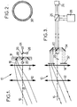
- FIG. 3 shows a possible constitution of the device, the principle diagram of which is given in FIG. 1.
- Each angular stop position of the mirror 20 corresponds to an optical sub-assembly comprising a diverging lens 32 providing an output beam parallel to the axis 16 and a mirror 34 returning to the rotating mirror 20.
- the lens 32 can be aspherical and constitute a corrective element. It can also be replaced or supplemented by a corrective element such as a blade with aspherical parallel faces or a holographic element.
- the separator 26 may be constituted by an electro-optical switch.
- the inlet opening diameter of such a device is only limited by the diameter which it is possible to give to the lenses 12 and 14. In the case of a device intended to operate in the infrared, comprising so germanium lenses, it is difficult to exceed a diameter of 50 cm.
- the telescope makes it possible to reduce the diameter of the input beam by a factor of around 10, within an acceptable size.
- the telescope can have the constitution shown in figure 4, with germanium lenses.
- the single lens 14 of FIG. 2 is replaced by two lenses with spherical surfaces 14a and 14b.
- the corrective element shown in FIG. 4 comprises a divergent lens 32 giving rise to a parallel beam and an aspherical blade 33 which serves to compensate for the residual aberrations.
- the speed measurement will generally be carried out by heterodyne detection on the signal supplied by the detector 24.
- a lens telescope like the one in Figure 3 does not allow to go beyond a scanning angle ⁇ of about 45 ° and an input diameter of about 50 cm, in infrared .
- a telescope with angularly distributed mirrors When looking for large scanning angles and / or entry diameters, you can use a telescope with angularly distributed mirrors.
- Figure 5 shows the basic construction of such a device.
- the telescope comprises several fractions, each materialized by a parabolic or pseudo-parabolic mirror 36, off axis.
- the number of fractions corresponds to the number of successive positions given to the scanning mirror 20 (usually from 4 to 20).
- the successive directions of emission and reception are all located on a cone whose apex angle is defined by the characteristics of the parabolic mirrors 36.
- a corrective element 32 is further interposed on each optical path, between the rotating mirror 20 and the respective parabolic mirror 36.
- the device shown in Figure 5, like that of Figure 3, allows without difficulty to reduce the diameter of the input-output beam in a ratio of about 10. It has the advantage of authorizing the obtaining of a sweeping cone with a half-angle at the top ⁇ high, which can easily exceed 45 °. In addition, the diameter of the beam emitted or received can easily exceed one meter.
- FIGS. 6 and 7 show a system comprising several devices 38 (three for example) which may have one of the constitutions described above, if not that they include a laser 28 and a common detector.
- the three devices have different orientations, so that the traces on the ground of the beam, assuming the fixed satellite, have an offset relative arrangement, like that shown in FIG. 7.
- the devices 38 are used successively by orienting the beams coming from their mirrors output turns 20 towards the switch 26, by means of an additional respective return mirror 40 and of a mirror rotating in some positions 42 controlled by a stepping motor 44.
- the reception beam has a width at least equivalent to a circle of 0.5 m in diameter.
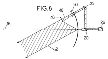
- the embodiment shown in Figure 8 achieves this result with limited space, reduced mass and relatively easy to perform elements.
- each aspherical mirror 46 - lens 50 assembly receives a beam comprised between the generator 48 of the scanning cone 8 and the beam 52.
- the mirror 36 is scalloped on each optical path to bypass the passage of light.
- the primary mirror 36 being spherical, its realization is easy. It can have a large aperture on the order of F / 0.5, which reduces the size of the telescope.
- the mirror 46 and the lens 50 are of revolution, so that they can be produced without difficulty by diamond machining.
- the aspherization of the system 46 - 50 is calculated so as to obtain a stigmatic system for the direction and to satisfy the condition of aplanetism around the direction 48.
- the lidar operates in step-by-step mode and that the optical parts are fixed during emission and reception of the laser pulse, the required field is practically zero.
- the existence of a nonzero field where the telescope is limited by diffraction, is useful on the one hand for the alignment of the telescope on the ground and on the other hand to take into account the defects of optical alignments in flight.
- a device actually produced comprises a mirror 36 1.4 m in diameter and eight to twelve sets 46 - 50 - 25 regularly distributed around the axis 16. Each set corresponds to a generator 48 and to an angular position of the scanning mirror 20.
Abstract
Description
La présente invention concerne les dispositifs embarquables sur véhicule aérien ou spatial, destinés à mesurer la rétrodiffusion de la lumière par une scène éloignée.The present invention relates to devices on board an air or space vehicle, intended for measuring the backscattering of light by a distant scene.
Elle concerne plus particulièrement les dispositifs de ce type, dits lidars, comprenant un laser d'émission d'impulsions de lumière courtes, une voie de réception du flux lumineux rétrodiffusé et des moyens optiques de balayage conique permettant d'orienter une direction commune d'émission du laser et de réception par ladite voie suivant des génératrices successives d'un cône.It relates more particularly to devices of this type, called lidars, comprising a laser for emitting short light pulses, a channel for receiving the backscattered light flux and conical scanning optical means making it possible to orient a common direction of emission of the laser and reception by said channel according to successive generators of a cone.
L'invention trouve une application importante dans le domaine des lidars embarqués sur satellite et destinés à l'exploration météorologique de la terre. Ces lidars émettent une impulsion laser, de quelques nanosecondes à quelques microsecondes de longueur, à travers un télescope. L'onde rétrodiffusée par les particules d'aérosol de l'atmosphère permet de mesurer des paramètres tels que la concentration des aérosols ou la vitesse des vents. Comme les couches successives de l'atmosphère sont atteintes par l'impulsion laser à des instants différents, un découpage du signal de retour par des fenêtres temporelles permet de dresser une carte des paramètres à travers l'épaisseur d'atmosphère sondée.The invention finds an important application in the field of lidars on board satellites and intended for meteorological exploration of the earth. These lidars emit a laser pulse, from a few nanoseconds to a few microseconds in length, through a telescope. The wave backscattered by aerosol particles from the atmosphere can measure parameters such as aerosol concentration or wind speed. As the successive layers of the atmosphere are reached by the laser pulse at different times, a cutting of the return signal by time windows makes it possible to draw up a map of the parameters across the thickness of the atmosphere probed.
Les lidars utilisés peuvent être incohérents : ils fournissent alors uniquement une information sur la variation de la densité d'aérosol en fonction de l'altitude et sur l'altitude des sommets des nuages, sauf si on détecte le décalage Doppler par une spectromètre tel qu'un Fabry-Pérot.The lidars used can be inconsistent: they then only provide information on the variation of the aerosol density as a function of the altitude and on the altitude of the tops of the clouds, unless the Doppler shift is detected by a spectrometer such as 'a Fabry-Pérot.
Plus souvent, on utilise des lidars cohérents, ou lidars Doppler, qui permettent de mesurer directement la vitesse des vents par effet Doppler et détection hétérodyne, l'onde rétrodiffusée subissant un décalage en fréquence proportionnel à la vitesse radiale relative de la cible. La vitesse du vent à une altitude donnée s'obtient alors en soustrayant, de la vitesse radiale relative mesurée, les contributions de la vitesse du porteur du dispositif et de la vitesse d'entraînement liée à la rotation de la terre.More often, we use coherent lidars, or Doppler lidars, which allow direct measurement of wind speed by Doppler effect and heterodyne detection, the backscattered wave undergoing a proportional frequency shift at the relative radial speed of the target. The wind speed at a given altitude is then obtained by subtracting, from the measured relative radial speed, the contributions from the speed of the carrier of the device and from the drive speed linked to the rotation of the earth.
Par une mesure Doppler, on obtient uniquement la projection de la vitesse sur la direction de visée de l'instrument. Un dispositif du genre ci-dessus destiné à des applications météorologiques est en conséquence avantageusement prévu pour mesurer au moins deux composantes de la vitesse, séparées d'environ 30°.By a Doppler measurement, one obtains only the projection of the speed on the direction of sight of the instrument. A device of the above type intended for meteorological applications is therefore advantageously provided for measuring at least two components of the speed, separated by approximately 30 °.
On a déjà proposé des dispositifs, montés sur satellite en orbite basse, du genre ci-dessus.Devices have already been proposed, mounted on low orbit satellites, of the above type.
La ligne de visée d'un télescope émetteur fixe par rapport au satellite décrit une courbe sur la surface de la terre qui reproduit la trace du satellite. Pour obtenir une bonne couverture de la terre, il est nécessaire que le dispositif sonde l'atmosphère de part et d'autre de la trace du satellite au sol. Pour cela, on a jusqu'ici proposé soit de déplacer l'ensemble du télescope, soit d'adjoindre au télescope un dispositif de balayage situé devant lui, tel qu'un miroir plan, donnant un balayage conique, qui se traduit par un tracé de balayage au sol en forme de cycloïde.The line of sight of a transmitting telescope fixed with respect to the satellite describes a curve on the surface of the earth which reproduces the track of the satellite. To obtain good coverage of the earth, it is necessary for the device to probe the atmosphere on either side of the trace of the satellite on the ground. For this, we have so far proposed either to move the entire telescope, or to add to the telescope a scanning device located in front of it, such as a plane mirror, giving a conical scan, which results in a line cycloid sweep on the ground.
Ces deux types de balayage connus ont des inconvénients graves du point de vue des contraintes mécaniques imposées à la plateforme du satellite. Si le télescope dans son entier est mobile, il génère des forces de réaction sur la plateforme, d'où des contraintes et la nécessité d'une compensation pour conserver un contrôle d'attitude du satellite. Si c'est un miroir ou prisme qui est déplaçable devant le satellite, il doit être de grande taille pour autoriser une ouverture importante.These two known types of scanning have serious drawbacks from the point of view of the mechanical constraints imposed on the satellite platform. If the entire telescope is mobile, it generates reaction forces on the platform, hence constraints and the need for compensation to maintain satellite attitude control. If it is a mirror or prism which is movable in front of the satellite, it must be of large size to allow a significant opening.
Dans la pratique, cela interdit d'utiliser une commande pas-à-pas : le télescope ou le miroir sont mis en rotation permanente. Cela induit deux effets parasites. L'onde rétrodiffusée n'est pas récupérée dans la même direction que l'onde émise, ce qui crée un phénomène d'aberration angulaire ; comme l'impulsion met un temps fini à traverser l'épaisseur de l'atmosphère, la direction de l'onde de retour varie pendant la durée du signal de retour, ce qui se traduit par un bougé de l'image.In practice, this prohibits the use of a step-by-step command: the telescope or the mirror are rotated permed. This induces two parasitic effects. The backscattered wave is not recovered in the same direction as the emitted wave, which creates an angular aberration phenomenon; as the pulse takes a finite time to pass through the thickness of the atmosphere, the direction of the return wave varies during the duration of the return signal, which results in a shake of the image.
On a également proposé (US-A-5071239) un télescope à balayage conique comprenant un objectif d'entrée, un miroir en forme d'anneau d'ellipsoïde et un miroir, tournant de façon continue, situé sur l'axe du cône.There has also been proposed (US-A-5071239) a conical scanning telescope comprising an input objective, a mirror in the form of an ellipsoid ring and a mirror, continuously rotating, situated on the axis of the cone.
L'invention vise notamment à fournir un dispositif du type ci-dessus défini, répondant mieux que ceux antérieurement connus aux exigences de la pratique. Elle vise notamment à réduire la masse et les dimensions des pièces mobiles nécessaires pour effectuer le balayage conique.The invention aims in particular to provide a device of the type defined above, which meets the requirements of practice better than those previously known. It aims in particular to reduce the mass and dimensions of the moving parts necessary to carry out the conical scanning.
Dans ce but, l'invention propose notamment un dispositif du genre ci-dessus défini, conforme à la revendication 1.To this end, the invention proposes in particular a device of the kind defined above, in accordance with claim 1.
Les réflecteurs peuvent être notamment constitués par des fractions hors d'axe de paraboloïde qui focalisent chacune un faisceau de lumière parallèle provenant de la scène observée vers le miroir rotatif. Ces fractions de paraboloïde constituent ainsi tout à la fois des réflecteurs et les composants de télescope successifs.The reflectors can in particular be constituted by fractions outside the paraboloid axis which each focus a parallel beam of light coming from the scene observed towards the rotating mirror. These paraboloid fractions thus constitute both reflectors and successive telescope components.
Dans un autre mode de réalisation, les réflecteurs sont disposés entre une optique à lentilles de réduction de diamètre du faisceau d'entrée et de sortie du dispositif et ledit miroir rotatif. Cette optique à lentilles peut comporter un télescope unique proprement dit et, pour chacune des directions de visée successives, un élément optique correcteur qui peut être également prévu pour donner naissance à un faisceau de lumière parallèle, dirigé parallèlement à l'axe de rotation du miroir rotatif, de diamètre beaucoup plus faible que le diamètre du faisceau d'entrée et de sortie du dispositif.In another embodiment, the reflectors are arranged between a lens reduction optic for the diameter of the input and output beam of the device and said rotary mirror. This lens optic can comprise a single telescope proper and, for each of the successive viewing directions, a corrective optical element which can also be provided to give rise to a parallel beam of light, directed parallel to the axis of rotation of the mirror. rotary, of much smaller diameter than the diameter of the input and output beam of the device.
Pour augmenter la couverture du satellite, il est possible de multiplier le nombre de traces au sol en associant plusieurs dispositifs du genre qui vient d'être définis, avec cependant un détecteur et un laser communs.To increase the coverage of the satellite, it is possible to multiply the number of tracks on the ground by associating several devices of the kind which has just been defined, with however a common detector and laser.
Les caractéristiques ci-dessus ainsi que d'autres apparaîtront mieux à la lecture de la description qui suit de modes particuliers de réalisation de l'invention, donnés à titre d'exemples non limitatifs. La description se réfère aux dessins qui l'accompagnent, dans lesquels :
- la figure 1 est un schéma de principe, destiné à faire apparaître des caractéristiques essentielles de l'invention ;
- la figure 2 montre, en tirets, l'allure du champ annulaire exploré dans le plan focal du télescope du dispositif de la figure 1 ;
- la figure 3, similaire à la figure 1, montre une constitution possible du dispositif dans le cas d'utilisation d'un télescope à lentilles ;
- la figure 4 montre une formule optique particulière utilisable dans le dispositif de la figure 3 ;
- la figure 5, similaire à la figure 3, montre la constitution générale d'un dispositif utilisant un télescope à miroir ;
- la figure 6 montre un dispositif comportant plusieurs télescopes, qui peuvent être chacun du genre montré en figure 1, 2 ou 5 ;
- la figure 7 montre une disposition possible du champ d'exploration de trois télescopes, suivant le montage de la figure 6 ; et
- la figure 8, similaire à la figure 1, montre une autre variante encore de réalisation.
- Figure 1 is a block diagram, intended to show essential features of the invention;
- FIG. 2 shows, in dashed lines, the shape of the annular field explored in the focal plane of the telescope of the device of FIG. 1;
- Figure 3, similar to Figure 1, shows a possible constitution of the device in the case of using a lens telescope;
- Figure 4 shows a particular optical formula usable in the device of Figure 3;
- Figure 5, similar to Figure 3, shows the general construction of a device using a mirror telescope;
- FIG. 6 shows a device comprising several telescopes, which may each be of the type shown in FIG. 1, 2 or 5;
- FIG. 7 shows a possible arrangement of the field of exploration of three telescopes, according to the assembly of FIG. 6; and
- Figure 8, similar to Figure 1, shows yet another alternative embodiment.
Le principe mis en oeuvre par l'invention est schématisé sur les figures 1 et 2. Le dispositif comporte un télescope 10, dioptrique dans le cas de la figure 1, constitué par une lentille d'entrée 12 et une lentille de champ 14. Ces lentilles sont calculées de façon qu'un faisceau parallèle incident suivant une direction d'angle d'incidence θ par rapport à l'axe 16 du télescope (cet axe 16 étant orienté vers le nadir lors de l'emploi sur satellite) donne naissance à un faisceau convergeant vers un plan focal 18, d'axe 19 parallèle à l'axe optique du télescope 16 qui constitue l'axe de balayage. Des moyens de balayage optique comportent un miroir 20 placé sur l'axe 16, ayant une dimension beaucoup plus faible que celle du faisceau d'entrée recueilli par la lentille 12. Un moteur pas-à-pas 22 permet de faire tourner le miroir 20 autour de l'axe 16.The principle implemented by the invention is shown diagrammatically in FIGS. 1 and 2. The device comprises a
Pour chaque position du miroir, c'est une fraction angulaire particulière de l'image annulaire 30 (figure 2) formée dans le plan focal et correspondant aux objets fournissant un faisceau arrivant sous l'incidence θ qui est renvoyée vers un détecteur 24. Un miroir de renvoi 25 correspond à chaque position possible du miroir 20. Un séparateur 26, représenté sur la figure 1 sous forme d'une lame semi-transparente, permet d'envoyer le faisceau fourni par un laser à impulsions 28 suivant un trajet de sortie coïncidant avec le trajet du faisceau d'entrée recueilli par le détecteur 24.For each position of the mirror, it is a particular angular fraction of the annular image 30 (FIG. 2) formed in the focal plane and corresponding to the objects providing a beam arriving under the incidence θ which is returned to a
Du fait de la faible inertie du miroir 20, il est possible de le faire avancer pas-à-pas, en le maintenant dans la même position pendant l'émission et jusqu'à la réception complète de l'écho de retour. On élimine ainsi les aberrations angulaires que provoquerait un balayage à vitesse angulaire constante. Le mouvement de translation du satellite n'induit en effet pas d'aberrations angulaires, du fait de la composition des vitesses. De plus, le mode de fonctionnement pas-à-pas permet de s'affranchir des microvibrations provenant d'un mécanisme de balayage continu.Due to the low inertia of the
Il est relativement facile de réaliser un télescope à lentilles donnant une image satisfaisante dans une zone annulaire du plan focal, telle que la zone 30 de la figure 2, éventuellement en plaçant un élément correcteur sur chaque trajet entre la lentille 40 et le séparateur. Il n'y a pas d'aberration chromatique, car l'onde émise par le laser 28 est pratiquement monochromatique. Le champ radial nécessaire est étroit, généralement de l'ordre du dixième de degré.It is relatively easy to make a lens telescope giving a satisfactory image in an annular zone of the focal plane, such as
La figure 3 montre une constitution possible du dispositif dont le schéma de principe est donné en figure 1. A chaque position angulaire d'arrêt du miroir 20 correspond un sous-ensemble optique comprenant une lentille divergente 32 fournissant un faisceau de sortie parallèle à l'axe 16 et un miroir 34 de renvoi vers le miroir rotatif 20. La lentille 32 peut être asphérique et constituer un élément correcteur. Elle peut aussi être remplacée ou complétée par un élément correcteur tel qu'une lame à faces parallèles asphériques ou un élément holographique. Le séparateur 26 peut être constitué par un commutateur électro-optique.FIG. 3 shows a possible constitution of the device, the principle diagram of which is given in FIG. 1. Each angular stop position of the
Le diamètre d'ouverture d'entrée d'un tel dispositif n'est limité que par le diamètre qu'il est possible de donner aux lentilles 12 et 14. Dans le cas d'un dispositif destiné à fonctionner dans l'infrarouge, comportant donc des lentilles en germanium, on peut difficilement dépasser un diamètre de 50 cm. Le télescope permet de réduire le diamètre du faisceau d'entrée par un facteur de 10 environ, dans un encombrement acceptable.The inlet opening diameter of such a device is only limited by the diameter which it is possible to give to the
Pour une meilleure correction des aberrations, le télescope peut avoir la constitution montrée en figure 4, avec des lentilles en germanium. La lentille unique 14 de la figure 2 est remplacée par deux lentilles à surfaces sphériques 14a et 14b. Le télescope présente une longueur focale de 540 mm, optimisée pour θ = 20°, avec un diamètre d'entrée de 400 mm sous cette incidence.For a better correction of the aberrations, the telescope can have the constitution shown in figure 4, with germanium lenses. The
L'élément correcteur montré en figure 4 comporte une lentille divergente 32 donnant naissance à un faisceau parallèle et une lame asphérique 33 qui sert à compenser les aberrations résiduelles.The corrective element shown in FIG. 4 comprises a
On ne décrira ni le laser 28, ni le détecteur 24 qui peuvent avoir l'une des constitutions connues. Dans le cas d'un laser Doppler, la mesure de vitesse s'effectuera généralement par détection hétérodyne sur le signal fourni par le détecteur 24.Neither the
Dans la pratique, un télescope à lentilles tel que celui de la figure 3 ne permet pas d'aller au-delà d'un angle de balayage θ de 45° environ et d'un diamètre d'entrée de 50 cm environ, en infrarouge. Lorsqu'on recherche des angles de balayage et/ou des diamètres d'entrée importants, on peut utiliser un télescope à miroirs répartis angulairement.In practice, a lens telescope like the one in Figure 3 does not allow to go beyond a scanning angle θ of about 45 ° and an input diameter of about 50 cm, in infrared . When looking for large scanning angles and / or entry diameters, you can use a telescope with angularly distributed mirrors.
La figure 5 (où les éléments correspondant à ceux de la figure 3 portent le même numéro de référence) montre la constitution de principe d'un tel dispositif. Le télescope comporte plusieurs fractions, matérialisées chacune par un miroir parabolique ou pseudo-parabolique 36, hors d'axe. Le nombre de fractions correspond au nombre de positions successives données au miroir de balayage 20 (habituellement de 4 à 20). Les directions successives d'émission et de réception sont toutes localisées sur un cône dont l'angle au sommet est défini par les caractéristiques des miroirs paraboliques 36. Un élément correcteur 32 est encore interposé sur chaque trajet optique, entre le miroir tournant 20 et le miroir parabolique respectif 36.Figure 5 (where the elements corresponding to those of Figure 3 have the same reference number) shows the basic construction of such a device. The telescope comprises several fractions, each materialized by a parabolic or
Le dispositif montré en figure 5, comme celui de la figure 3, permet sans difficulté de réduire le diamètre du faisceau d'entrée-sortie dans un rapport de 10 environ. Il présente l'avantage d'autoriser l'obtention d'un cône de balayage de demi-angle au sommet θ élevé, pouvant aisément dépasser 45°. De plus, le diamètre du faisceau émis ou reçu peut facilement dépasser un mètre.The device shown in Figure 5, like that of Figure 3, allows without difficulty to reduce the diameter of the input-output beam in a ratio of about 10. It has the advantage of authorizing the obtaining of a sweeping cone with a half-angle at the top θ high, which can easily exceed 45 °. In addition, the diameter of the beam emitted or received can easily exceed one meter.
Les figures 6 et 7 montrent un système comportant plusieurs dispositifs 38 (trois par exemple) pouvant avoir l'une des constitutions précédemment décrites, si ce n'est qu'ils comportent un laser 28 et un détecteur commun. Les trois dispositifs ont des orientations différentes, pour que les traces au sol du faisceau, à supposer le satellite fixe, présentent une disposition relative décalée, comme celle montrée en figure 7. Les dispositifs 38 sont utilisés successivement en orientant les faisceaux provenant de leurs miroirs tournants de sortie 20 vers le commutateur 26, par l'intermédiaire d'un miroir de renvoi respectif supplémentaire 40 et d'un miroir tournant à quelques positions 42 commandé par un moteur pas-à-pas 44.FIGS. 6 and 7 show a system comprising several devices 38 (three for example) which may have one of the constitutions described above, if not that they include a
Pour certaines applications, et notamment sur les satellites, où la puissance électrique est limitée à environ 1 kW du fait de la dimension des panneaux solaires et où la puissance du laser est elle aussi limitée, il est souhaitable que le faisceau de réception ait une largeur au moins équivalente à un cercle de 0,5 m de diamètre. Le mode de réalisation montré en figure 8 permet d'atteindre ce résultat avec un encombrement limité, une masse réduite et des éléments relativement faciles à réaliser.For certain applications, and in particular on satellites, where the electric power is limited to about 1 kW due to the size of the solar panels and where the laser power is also limited, it is desirable that the reception beam has a width at least equivalent to a circle of 0.5 m in diameter. The embodiment shown in Figure 8 achieves this result with limited space, reduced mass and relatively easy to perform elements.
Le dispositif montré en figure 8, où les éléments correspondant à ceux de la figure 1, sont désignés par les mêmes numéros de référence, autorise un balayage autour de l'axe 16. Il comporte un miroir sphérique 36, dont le centre de courbure C est placé sur l'axe 16. A chaque orientation que peut prendre le miroir de balayage 20 correspond un trajet optique sur lequel sont placés un miroir asphérique de révolution 46, dont l'axe de révolution 48 passe par le point C et constitue une génératrice du cône de balayage, une lentille correctrice 50 de révolution, également d'axe 48, et un élément déviateur 25 qui peut être un miroir plan ou un prisme.The device shown in Figure 8, where the elements corresponding to those of Figure 1, are designated by the same reference numbers, allows scanning around the
La puissance optique et l'ouverture de chaque ensemble miroir asphérique 46 - lentille 50 sont telles qu'il reçoit un faisceau compris entre la génératrice 48 du cône de balayage 8 et le rayon 52. Le miroir 36 est échancré sur chaque chemin optique pour contourner le passage de la lumière.The optical power and the opening of each aspherical mirror 46 -
Le miroir primaire 36 étant sphérique, sa réalisation est facile. Il peut avoir une grande ouverture de l'ordre de F/0,5, ce qui réduit l'encombrement du télescope. Le miroir 46 et la lentille 50 sont de révolution, de sorte qu'ils peuvent être réalisés sans difficultés par usinage au diamant. L'asphérisation du système 46 - 50 est calculée de manière à obtenir un système stigmatique pour la direction et à satisfaire la condition d'aplanétisme autour de la direction 48. Comme le lidar fonctionne en mode pas-à-pas et que les pièces optiques sont fixes pendant l'émission et la réception de l'impulsion laser, le champ requis est pratiquement nul. Dans la pratique, l'existence d'un champ non nul, où le télescope est limité par la diffraction, est utile d'une part pour l'alignement du télescope au sol et d'autre part pour prendre en compte les défauts d'alignements des optiques en vol.The
Un dispositif effectivement réalisé comprend un miroir 36 de 1,4 m de diamètre et huit à douze ensembles 46 - 50 - 25 régulièrement répartis autour de l'axe 16. Chaque ensemble correspond à une génératrice 48 et à une position angulaire du miroir de balayage 20.A device actually produced comprises a
Un tel dispositif pour un lidar utilisant un laser à CO₂ à 9,11 µm de laongueur dénote les caractéristiques suivantes :
- Pupille d'entrée (diamètre du faisceau) : 700 mm
- Diamètre du miroir 36 : 1.420 mm
- Nombre de sous-ensembles (46, 50, 25) : 8
- Angle au sommet du cône de balayage : 60 degrés
- Champ utlisable au voisinage de 48 (erreur < λ / 14 rms) : +/-300 µrad autour de 48.
- Entrance pupil (beam diameter): 700 mm
- Mirror diameter 36: 1.420 mm
- Number of sub-assemblies (46, 50, 25): 8
- Angle at the top of the scanning cone: 60 degrees
- Field usable in the vicinity of 48 (error <λ / 14 rms): +/- 300 µrad around 48.
Claims (11)
caractérisé en ce que lesdits moyens optiques comprennent un miroir (20) rotatif pas-à-pas autour d'un axe de balayage (16) de renvoi d'un chemin optique commun à un détecteur de réception (24) et au laser (28) vers des directions successives réparties à intervalles angulaires réguliers égaux au pas autour de l'axe de balayage (16) et plusieurs réflecteurs fixes (25;34;36) répartis auxdits intervalles, successivement associés au chemin optique commun par le miroir rotatif, lesdits réflecteurs fixes (25;34;36) étant prévus pour correspondre à des orientations de sondage différentes suivant ledit cône et ledit miroir rotatif (20) ayant une taille très inférieure à celle du faisceau d'entrée et de sortie du dispositif.On-board device on air or space vehicle comprising a laser (28) for emitting short light pulses, a channel for receiving the backscattered light flux and conical scanning optical means making it possible to orient a common direction of emission of the laser and of reception by said channel following successive generators of a cone,
characterized in that said optical means comprise a mirror (20) rotating step by step around a scanning axis (16) returning an optical path common to a reception detector (24) and to the laser (28 ) towards successive directions distributed at regular angular intervals equal to the pitch around the scanning axis (16) and several fixed reflectors (25; 34; 36) distributed at said intervals, successively associated with the common optical path by the rotating mirror, said fixed reflectors (25; 34; 36) being provided to correspond to different sounding orientations along said cone and said rotating mirror (20) having a size much smaller than that of the input and output beam of the device.
une optique de réduction de diamètre du faisceau d'entrée ayant un miroir sphérique (36) commun à toutes les voies, un miroir asphérique de correction (46) et une lentille asphérique (50), et
ledit miroir rotatif (20).Device according to claim 1, characterized in that said reflectors are constituted by plane mirrors (25) and each arranged on an optical path between:
an optical system for reducing the diameter of the input beam having a spherical mirror (36) common to all the channels, an aspherical correction mirror (46) and an aspherical lens (50), and
said rotating mirror (20).
Applications Claiming Priority (2)
| Application Number | Priority Date | Filing Date | Title |
|---|---|---|---|
| FR9410905 | 1994-09-13 | ||
| FR9410905A FR2724464B1 (en) | 1994-09-13 | 1994-09-13 | ON-BOARD DEVICE FOR MEASURING LIGHT BACK BROADCAST |
Publications (2)
| Publication Number | Publication Date |
|---|---|
| EP0702246A1 true EP0702246A1 (en) | 1996-03-20 |
| EP0702246B1 EP0702246B1 (en) | 1997-11-19 |
Family
ID=9466890
Family Applications (1)
| Application Number | Title | Priority Date | Filing Date |
|---|---|---|---|
| EP95402062A Expired - Lifetime EP0702246B1 (en) | 1994-09-13 | 1995-09-12 | Portable device for measuring the backscattering of light |
Country Status (6)
| Country | Link |
|---|---|
| US (1) | US5598263A (en) |
| EP (1) | EP0702246B1 (en) |
| JP (1) | JPH08178749A (en) |
| DE (1) | DE69501072T2 (en) |
| ES (1) | ES2110303T3 (en) |
| FR (1) | FR2724464B1 (en) |
Cited By (1)
| Publication number | Priority date | Publication date | Assignee | Title |
|---|---|---|---|---|
| EP3026475A1 (en) * | 2014-11-25 | 2016-06-01 | NCR Corporation | Scanner with adjustable field of view |
Families Citing this family (10)
| Publication number | Priority date | Publication date | Assignee | Title |
|---|---|---|---|---|
| FR2766931B1 (en) * | 1997-08-01 | 1999-10-15 | Sextant Avionique | OPTICAL DEVICE FOR A HELMET SIGHT COMPRISING AN ASPHERIC MIRROR |
| FR2833086B1 (en) * | 2001-11-30 | 2004-02-27 | Thales Sa | HIGH-SPEED SECTORAL OR PANORAMIC OPTRONIC WATCH DEVICE WITHOUT APPARENT MOVEMENT |
| IT1391180B1 (en) * | 2008-07-07 | 2011-11-18 | Consiglio Nazionale Ricerche | PROCEDURE FOR THE CHARACTERIZATION OF THE ATMOSPHERIC PARTICULATE BY MEANS OF A LIDAR DEVICE FOR ELASTIC AND RETRO-REFLECTION REFLECTION, AND LIDAR SYSTEM FOR IMPLEMENTING THE PROCEDURE |
| US7920262B2 (en) * | 2008-09-17 | 2011-04-05 | The United States Of America As Represented By The Secretary Of The Army | Systems for measuring backscattered light using rotating mirror |
| US8169596B2 (en) * | 2009-08-17 | 2012-05-01 | Seegrid Corporation | System and method using a multi-plane curtain |
| EP3220160B9 (en) * | 2016-03-14 | 2020-03-04 | Riegl Laser Measurement Systems GmbH | Flying device with laser scanner |
| US11474254B2 (en) | 2017-11-07 | 2022-10-18 | Piaggio Fast Forward Inc. | Multi-axes scanning system from single-axis scanner |
| DE102018125826A1 (en) | 2018-10-18 | 2020-04-23 | Sick Ag | Optoelectronic sensor and method for detecting objects |
| DE102020102247A1 (en) * | 2020-01-30 | 2021-08-05 | Sick Ag | Optoelectronic sensor and method for detecting objects |
| US20230393245A1 (en) * | 2020-10-23 | 2023-12-07 | Sense Photonics, Inc. | Integrated long-range narrow-fov and short-range wide-fov solid-state flash lidar system |
Citations (4)
| Publication number | Priority date | Publication date | Assignee | Title |
|---|---|---|---|---|
| US4340299A (en) * | 1980-03-13 | 1982-07-20 | United Technologies Corporation | Optical doppler radar system using a conically scanned laser beam |
| DE9010222U1 (en) * | 1990-07-05 | 1991-08-01 | Birkle, Gebhard, 7750 Konstanz, De | |
| US5071239A (en) | 1989-02-23 | 1991-12-10 | United Technologies Corporation | Catadioptric conically scanning telescope |
| US5255065A (en) * | 1992-03-10 | 1993-10-19 | The United States Of America As Represented By The Administrator Of The National Aeronautics And Space Administration | Conically scanned holographic lidar telescope |
Family Cites Families (3)
| Publication number | Priority date | Publication date | Assignee | Title |
|---|---|---|---|---|
| US4328421A (en) * | 1980-02-25 | 1982-05-04 | Barnes Engineering Company | Horizon sensor |
| US4459024A (en) * | 1981-12-09 | 1984-07-10 | Conoco Inc. | Method and apparatus for light detection and ranging for use in visually obstructed areas |
| US5418608A (en) * | 1993-05-04 | 1995-05-23 | Harbor Branch Oceanographic Institution Inc. | Three dimensional mapping systems and methods |
-
1994
- 1994-09-13 FR FR9410905A patent/FR2724464B1/en not_active Expired - Lifetime
-
1995
- 1995-09-12 US US08/526,932 patent/US5598263A/en not_active Expired - Lifetime
- 1995-09-12 EP EP95402062A patent/EP0702246B1/en not_active Expired - Lifetime
- 1995-09-12 ES ES95402062T patent/ES2110303T3/en not_active Expired - Lifetime
- 1995-09-12 DE DE69501072T patent/DE69501072T2/en not_active Expired - Lifetime
- 1995-09-13 JP JP7235642A patent/JPH08178749A/en not_active Withdrawn
Patent Citations (4)
| Publication number | Priority date | Publication date | Assignee | Title |
|---|---|---|---|---|
| US4340299A (en) * | 1980-03-13 | 1982-07-20 | United Technologies Corporation | Optical doppler radar system using a conically scanned laser beam |
| US5071239A (en) | 1989-02-23 | 1991-12-10 | United Technologies Corporation | Catadioptric conically scanning telescope |
| DE9010222U1 (en) * | 1990-07-05 | 1991-08-01 | Birkle, Gebhard, 7750 Konstanz, De | |
| US5255065A (en) * | 1992-03-10 | 1993-10-19 | The United States Of America As Represented By The Administrator Of The National Aeronautics And Space Administration | Conically scanned holographic lidar telescope |
Cited By (1)
| Publication number | Priority date | Publication date | Assignee | Title |
|---|---|---|---|---|
| EP3026475A1 (en) * | 2014-11-25 | 2016-06-01 | NCR Corporation | Scanner with adjustable field of view |
Also Published As
| Publication number | Publication date |
|---|---|
| JPH08178749A (en) | 1996-07-12 |
| DE69501072T2 (en) | 1998-06-18 |
| US5598263A (en) | 1997-01-28 |
| EP0702246B1 (en) | 1997-11-19 |
| FR2724464A1 (en) | 1996-03-15 |
| DE69501072D1 (en) | 1998-01-02 |
| ES2110303T3 (en) | 1998-02-01 |
| FR2724464B1 (en) | 1996-11-22 |
Similar Documents
| Publication | Publication Date | Title |
|---|---|---|
| EP0004227B1 (en) | System for optoelectrical detection and angular location of a luminous object and its use | |
| EP0419320B1 (en) | Automatic harmonizing device for an opto-electronic system | |
| EP0702246B1 (en) | Portable device for measuring the backscattering of light | |
| EP2173042B1 (en) | Optical transmission-reception unit with controllable transmission direction | |
| EP0034772B1 (en) | Device for determining the angular position of a target illuminated by light pulses | |
| FR2690997A1 (en) | Optoelectronic target acquisition system with very large field. | |
| FR2686312A1 (en) | Laser-observation space vehicle, especially for wind speeds, and observation instrument designed to form part thereof | |
| EP0241374A1 (en) | Optronic off-bore sight system for the spatial and spectral discrimination of infrared light sources | |
| EP0778958B1 (en) | Orientation locating system for an observation instrument | |
| FR2505505A1 (en) | Laser detecting and neutralising enemy tank optical system - uses optical system with aligning mirror to control beam elevation and bearing | |
| EP0353138A1 (en) | Multispectral mirror device | |
| EP0189217A1 (en) | Optical-mechanical analyser with a fixed telemetric field | |
| EP0645020A1 (en) | Omnidirectional surveillance device with optimal coverage of surrounding space by means of contiguous fields | |
| EP3607352B1 (en) | Device for acquiring data on a target, platform and method therefor | |
| EP1449020B1 (en) | High-speed sectorial or panoramic surveillance device without apparent motion | |
| FR2539864A1 (en) | LIGHT BEAM GUIDING SYSTEM | |
| EP1856552B1 (en) | Device for countering and tracking a threat in the form of a homing-head missile | |
| FR2690532A1 (en) | Pointing, or aiming, device for optical equipment e.g. for satellite communication using modulated laser beam - has system of two mirrors rotating about axes perpendicular to each other with fine tuning of first mirror | |
| FR2576115A1 (en) | OPTICAL MECHANICAL ANALYZER HAVING A FIELD OF FIXED TELEMETRY | |
| EP0684488A1 (en) | Space instrument for laser observation, and space vehicle including it | |
| FR2525339A1 (en) | Laser missile acquisition system for guidance control - uses computer to calculate laser beam pointing direction from missile and target position datA | |
| FR2654218A1 (en) | Optronic system for three-dimensional tracking with automatic alignment of an optical range-finder on the target | |
| WO2024002965A1 (en) | System for determining the attenuation of a light wave passing through a sampling volume | |
| EP0561680A1 (en) | Apparatus for measuring axial speed | |
| WO2007045638A1 (en) | Dual-laser-scanning optical device having multiple adjustable parameters |
Legal Events
| Date | Code | Title | Description |
|---|---|---|---|
| PUAI | Public reference made under article 153(3) epc to a published international application that has entered the european phase |
Free format text: ORIGINAL CODE: 0009012 |
|
| AK | Designated contracting states |
Kind code of ref document: A1 Designated state(s): BE DE ES GB IT NL |
|
| 17P | Request for examination filed |
Effective date: 19960409 |
|
| GRAG | Despatch of communication of intention to grant |
Free format text: ORIGINAL CODE: EPIDOS AGRA |
|
| 17Q | First examination report despatched |
Effective date: 19970321 |
|
| GRAH | Despatch of communication of intention to grant a patent |
Free format text: ORIGINAL CODE: EPIDOS IGRA |
|
| GRAH | Despatch of communication of intention to grant a patent |
Free format text: ORIGINAL CODE: EPIDOS IGRA |
|
| GRAA | (expected) grant |
Free format text: ORIGINAL CODE: 0009210 |
|
| AK | Designated contracting states |
Kind code of ref document: B1 Designated state(s): BE DE ES GB IT NL |
|
| GBT | Gb: translation of ep patent filed (gb section 77(6)(a)/1977) |
Effective date: 19971117 |
|
| ITF | It: translation for a ep patent filed |
Owner name: GUZZI E RAVIZZA S.R.L. |
|
| REF | Corresponds to: |
Ref document number: 69501072 Country of ref document: DE Date of ref document: 19980102 |
|
| REG | Reference to a national code |
Ref country code: ES Ref legal event code: FG2A Ref document number: 2110303 Country of ref document: ES Kind code of ref document: T3 |
|
| PLBE | No opposition filed within time limit |
Free format text: ORIGINAL CODE: 0009261 |
|
| STAA | Information on the status of an ep patent application or granted ep patent |
Free format text: STATUS: NO OPPOSITION FILED WITHIN TIME LIMIT |
|
| 26N | No opposition filed | ||
| REG | Reference to a national code |
Ref country code: GB Ref legal event code: IF02 |
|
| PGFP | Annual fee paid to national office [announced via postgrant information from national office to epo] |
Ref country code: NL Payment date: 20020815 Year of fee payment: 8 |
|
| PGFP | Annual fee paid to national office [announced via postgrant information from national office to epo] |
Ref country code: ES Payment date: 20020826 Year of fee payment: 8 |
|
| PGFP | Annual fee paid to national office [announced via postgrant information from national office to epo] |
Ref country code: BE Payment date: 20021011 Year of fee payment: 8 |
|
| PG25 | Lapsed in a contracting state [announced via postgrant information from national office to epo] |
Ref country code: ES Free format text: LAPSE BECAUSE OF NON-PAYMENT OF DUE FEES Effective date: 20030913 |
|
| PG25 | Lapsed in a contracting state [announced via postgrant information from national office to epo] |
Ref country code: BE Free format text: LAPSE BECAUSE OF NON-PAYMENT OF DUE FEES Effective date: 20030930 |
|
| BERE | Be: lapsed |
Owner name: *MATRA MARCONI SPACE FRANCE Effective date: 20030930 |
|
| PG25 | Lapsed in a contracting state [announced via postgrant information from national office to epo] |
Ref country code: NL Free format text: LAPSE BECAUSE OF NON-PAYMENT OF DUE FEES Effective date: 20040401 |
|
| NLV4 | Nl: lapsed or anulled due to non-payment of the annual fee |
Effective date: 20040401 |
|
| REG | Reference to a national code |
Ref country code: ES Ref legal event code: FD2A Effective date: 20030913 |
|
| PGFP | Annual fee paid to national office [announced via postgrant information from national office to epo] |
Ref country code: DE Payment date: 20100910 Year of fee payment: 16 |
|
| PGFP | Annual fee paid to national office [announced via postgrant information from national office to epo] |
Ref country code: GB Payment date: 20110824 Year of fee payment: 17 |
|
| PGFP | Annual fee paid to national office [announced via postgrant information from national office to epo] |
Ref country code: IT Payment date: 20110926 Year of fee payment: 17 |
|
| GBPC | Gb: european patent ceased through non-payment of renewal fee |
Effective date: 20120912 |
|
| PG25 | Lapsed in a contracting state [announced via postgrant information from national office to epo] |
Ref country code: DE Free format text: LAPSE BECAUSE OF NON-PAYMENT OF DUE FEES Effective date: 20130403 Ref country code: GB Free format text: LAPSE BECAUSE OF NON-PAYMENT OF DUE FEES Effective date: 20120912 |
|
| PG25 | Lapsed in a contracting state [announced via postgrant information from national office to epo] |
Ref country code: IT Free format text: LAPSE BECAUSE OF NON-PAYMENT OF DUE FEES Effective date: 20120912 |
|
| REG | Reference to a national code |
Ref country code: DE Ref legal event code: R119 Ref document number: 69501072 Country of ref document: DE Effective date: 20130403 |