EP1209441A1 - Dispositif de relèvement tridimensionnel d'une scène à émission laser - Google Patents
Dispositif de relèvement tridimensionnel d'une scène à émission laser Download PDFInfo
- Publication number
- EP1209441A1 EP1209441A1 EP01403013A EP01403013A EP1209441A1 EP 1209441 A1 EP1209441 A1 EP 1209441A1 EP 01403013 A EP01403013 A EP 01403013A EP 01403013 A EP01403013 A EP 01403013A EP 1209441 A1 EP1209441 A1 EP 1209441A1
- Authority
- EP
- European Patent Office
- Prior art keywords
- axis
- lifting device
- rotation
- dimensional lifting
- laser beam
- Prior art date
- Legal status (The legal status is an assumption and is not a legal conclusion. Google has not performed a legal analysis and makes no representation as to the accuracy of the status listed.)
- Granted
Links
- 230000003287 optical effect Effects 0.000 claims abstract description 42
- 238000000034 method Methods 0.000 claims abstract description 7
- 230000001965 increasing effect Effects 0.000 claims abstract description 4
- 239000012528 membrane Substances 0.000 claims description 19
- 230000009975 flexible effect Effects 0.000 claims description 10
- 239000000523 sample Substances 0.000 claims description 10
- 230000005540 biological transmission Effects 0.000 claims description 9
- 230000001603 reducing effect Effects 0.000 claims description 9
- 238000006073 displacement reaction Methods 0.000 claims description 8
- 230000005291 magnetic effect Effects 0.000 claims description 7
- 239000013307 optical fiber Substances 0.000 claims description 6
- 238000003860 storage Methods 0.000 claims description 4
- 230000008093 supporting effect Effects 0.000 claims description 4
- 230000003213 activating effect Effects 0.000 claims description 3
- 230000003321 amplification Effects 0.000 claims description 3
- 238000003199 nucleic acid amplification method Methods 0.000 claims description 3
- 238000012800 visualization Methods 0.000 claims description 3
- 238000011084 recovery Methods 0.000 claims 1
- 238000005259 measurement Methods 0.000 description 10
- 201000009310 astigmatism Diseases 0.000 description 9
- 230000008901 benefit Effects 0.000 description 8
- 238000012937 correction Methods 0.000 description 3
- 230000000694 effects Effects 0.000 description 3
- 239000000835 fiber Substances 0.000 description 3
- 235000010603 pastilles Nutrition 0.000 description 3
- 230000009467 reduction Effects 0.000 description 3
- 238000004364 calculation method Methods 0.000 description 2
- 238000010586 diagram Methods 0.000 description 2
- 230000033001 locomotion Effects 0.000 description 2
- 230000000051 modifying effect Effects 0.000 description 2
- 230000008569 process Effects 0.000 description 2
- 241000735470 Juncus Species 0.000 description 1
- 241001417935 Platycephalidae Species 0.000 description 1
- 241001080024 Telles Species 0.000 description 1
- 230000004913 activation Effects 0.000 description 1
- 230000006978 adaptation Effects 0.000 description 1
- 230000002238 attenuated effect Effects 0.000 description 1
- 239000003638 chemical reducing agent Substances 0.000 description 1
- 238000010276 construction Methods 0.000 description 1
- 238000005520 cutting process Methods 0.000 description 1
- 238000001914 filtration Methods 0.000 description 1
- 230000036961 partial effect Effects 0.000 description 1
- 239000008188 pellet Substances 0.000 description 1
- 230000002093 peripheral effect Effects 0.000 description 1
- 230000010287 polarization Effects 0.000 description 1
- 230000003405 preventing effect Effects 0.000 description 1
- 238000010010 raising Methods 0.000 description 1
- 230000002829 reductive effect Effects 0.000 description 1
- 238000000926 separation method Methods 0.000 description 1
- 230000003068 static effect Effects 0.000 description 1
- 230000007704 transition Effects 0.000 description 1
- 238000013519 translation Methods 0.000 description 1
Images


Classifications
-
- G—PHYSICS
- G01—MEASURING; TESTING
- G01B—MEASURING LENGTH, THICKNESS OR SIMILAR LINEAR DIMENSIONS; MEASURING ANGLES; MEASURING AREAS; MEASURING IRREGULARITIES OF SURFACES OR CONTOURS
- G01B11/00—Measuring arrangements characterised by the use of optical techniques
- G01B11/002—Measuring arrangements characterised by the use of optical techniques for measuring two or more coordinates
-
- G—PHYSICS
- G01—MEASURING; TESTING
- G01B—MEASURING LENGTH, THICKNESS OR SIMILAR LINEAR DIMENSIONS; MEASURING ANGLES; MEASURING AREAS; MEASURING IRREGULARITIES OF SURFACES OR CONTOURS
- G01B11/00—Measuring arrangements characterised by the use of optical techniques
- G01B11/24—Measuring arrangements characterised by the use of optical techniques for measuring contours or curvatures
-
- G—PHYSICS
- G01—MEASURING; TESTING
- G01C—MEASURING DISTANCES, LEVELS OR BEARINGS; SURVEYING; NAVIGATION; GYROSCOPIC INSTRUMENTS; PHOTOGRAMMETRY OR VIDEOGRAMMETRY
- G01C11/00—Photogrammetry or videogrammetry, e.g. stereogrammetry; Photographic surveying
-
- G—PHYSICS
- G01—MEASURING; TESTING
- G01S—RADIO DIRECTION-FINDING; RADIO NAVIGATION; DETERMINING DISTANCE OR VELOCITY BY USE OF RADIO WAVES; LOCATING OR PRESENCE-DETECTING BY USE OF THE REFLECTION OR RERADIATION OF RADIO WAVES; ANALOGOUS ARRANGEMENTS USING OTHER WAVES
- G01S17/00—Systems using the reflection or reradiation of electromagnetic waves other than radio waves, e.g. lidar systems
- G01S17/02—Systems using the reflection of electromagnetic waves other than radio waves
- G01S17/06—Systems determining position data of a target
- G01S17/42—Simultaneous measurement of distance and other co-ordinates
-
- G—PHYSICS
- G01—MEASURING; TESTING
- G01S—RADIO DIRECTION-FINDING; RADIO NAVIGATION; DETERMINING DISTANCE OR VELOCITY BY USE OF RADIO WAVES; LOCATING OR PRESENCE-DETECTING BY USE OF THE REFLECTION OR RERADIATION OF RADIO WAVES; ANALOGOUS ARRANGEMENTS USING OTHER WAVES
- G01S7/00—Details of systems according to groups G01S13/00, G01S15/00, G01S17/00
- G01S7/48—Details of systems according to groups G01S13/00, G01S15/00, G01S17/00 of systems according to group G01S17/00
- G01S7/481—Constructional features, e.g. arrangements of optical elements
- G01S7/4817—Constructional features, e.g. arrangements of optical elements relating to scanning
-
- G—PHYSICS
- G02—OPTICS
- G02B—OPTICAL ELEMENTS, SYSTEMS OR APPARATUS
- G02B26/00—Optical devices or arrangements for the control of light using movable or deformable optical elements
- G02B26/08—Optical devices or arrangements for the control of light using movable or deformable optical elements for controlling the direction of light
- G02B26/10—Scanning systems
- G02B26/101—Scanning systems with both horizontal and vertical deflecting means, e.g. raster or XY scanners
-
- G—PHYSICS
- G01—MEASURING; TESTING
- G01S—RADIO DIRECTION-FINDING; RADIO NAVIGATION; DETERMINING DISTANCE OR VELOCITY BY USE OF RADIO WAVES; LOCATING OR PRESENCE-DETECTING BY USE OF THE REFLECTION OR RERADIATION OF RADIO WAVES; ANALOGOUS ARRANGEMENTS USING OTHER WAVES
- G01S17/00—Systems using the reflection or reradiation of electromagnetic waves other than radio waves, e.g. lidar systems
- G01S17/88—Lidar systems specially adapted for specific applications
- G01S17/89—Lidar systems specially adapted for specific applications for mapping or imaging
Definitions
- the present invention relates to a lifting device three-dimensional scene.
- the present invention relates to a device for three-dimensional bearing, comprising a laser transmitter, means of scanning along first and second axes of rotation to scan the scene at using a laser beam emitted by the laser transmitter, a photosensitive receiver an image of a spot created by the laser beam on the scene, means of focusing of the laser beam backscattered by the scene towards the receiver photosensitive, from the first means of measuring the orientation of the beam to the output of the scanning means, and second means for measuring the distance between the device and the spot by laser telemetry, including a blade separator of the beams emitted and backscattered by the scene.
- Such a device comprises a laser pulse emitter, scanning means comprising two free galvanometric mirrors rotating around two respective axes orthogonal, and encoders to direct the laser beam and determine the orientation of it, depending on the positions of the two mirrors galvanometer.
- scanning means comprising two free galvanometric mirrors rotating around two respective axes orthogonal, and encoders to direct the laser beam and determine the orientation of it, depending on the positions of the two mirrors galvanometer.
- it includes an optical beam splitter by the pulse emitter and the beam backscattered by the scene, which allows measure the distance between the device and the spot created by the laser beam on the scene, by measuring the "flight time" of the laser pulse.
- the device also includes means for measuring the instant of emission of the laser beam and of the means for measuring the instant of reception by a photosensitive receiver of the beam backscattered by the scene.
- a pulse emitted by the laser transmitter is partially reflected by the separator towards the two galvanometric mirrors to create a spot on the stage.
- Part of the impulse received by the scene is then backscattered to the two galvanometric mirrors, then crosses the separator to be received by a telescope focusing its energy on the receiver photosensitive.
- the device When the device applies to measurements spanning a large range of distances, such as conventionally from 1 to 100 meters, the energy of the backscattered beam being inversely proportional to the square of the distance from the spot to the device, the measurement made by the receiver photosensitive can suffer from large beam energy dynamics received by him.
- the invention aims to remedy this drawback by creating a device able to limit and then take into account the energy dynamics of backscattered beams received by the photosensitive receiver.
- the invention therefore relates to a lifting device three-dimensional scene, comprising a laser transmitter, means for scanning along first and second axes of rotation to scan the scene at using a laser beam emitted by the laser transmitter, a photosensitive receiver an image of a spot created by the laser beam on the scene, means of focusing of the laser beam backscattered by the scene towards the receiver photosensitive, from the first means of measuring the orientation of the beam to the output of the scanning means, and second means for measuring the distance between the device and the spot by laser telemetry, said second means measuring device comprising a separating plate for the emitted and backscattered beams by the scene, characterized in that the focusing means comprise a converging optical system associated with a diverging optical system increasing the focal length of the converging optical system forming thus a telephoto lens, and in that the scanning means comprise at least a mirror placed on the path of the emitted and backscattered laser beams, between the focusing means and the scene.
- the device according to the invention makes it possible to compensate for the dynamic of the energy of the backscattered beam received by the photosensitive receiver, in providing focusing means having a large focal length and a low focal length footprint.
- the focal length of the focusing means increases the size of the spot image created on the receiver photosensitive, so that it completely covers it, even when the spot is very far from the device.
- the size of its image at the photosensitive receptor increases inversely proportional to the square of the distance separating the spot from the device, as beam energy.
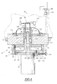
- a lifting device 2 three-dimensional of a scene 4 materialized by a pottery for example, has a housing 6 in which is a window 8 transparent to light beams.
- This housing 6 has two parts.
- a first part, in which the window 8 is located, comprises optical systems and constitutes the opto-mechanical part 10 of the device 2.
- a second part, located below the first part, contains electronic systems, the essential elements of which will be described with reference to FIGS. 8 and 9 and constitutes the electronic part 12 of the device 2.
- This electronic part includes calculation and storage of sufficient data to implement methods of raising, representing, modifying or activating the opto-mechanical part 10, classics.
- the electronic part 12 includes an architecture of on-board microcomputer including a backplane capable of accommodating electronic cards supporting different formats of transmission bus data, such as PCI, ISA buses.
- It also has a compact microcomputer card equipped with a static hard disk, and piloting cards of different elements opto-mechanical part 10 and electronic part 12, which will be described thereafter.
- the electronic part 12 is connected to a device for external control (not shown), such as a laptop or electronic personal organizer, using an ethernet link.
- This platform 14 is enslaved in angular position around a vertical axis 16 cutting it into sound center by a servo device which will be described with reference to the figure 3, thus allowing a scanning of the scene 4 by the device 2.
- the laser transmitter 20, the autofocus system 22, the prismatic blade 24 and the assembly constituted by the separating blade 32 and the semi-reflecting patch 34, are arranged so that the axes 16, 26 and 36 are rigorously coplanar.
- a laser beam emitted by the laser emitter 20 on the axis 26 reaches the prismatic plate 24 after having passed through the focusing assembly 22 automatic. It enters the prismatic plate 24 through a first flat surface 24a of separation, perpendicular to the axis 26.
- This reflected part of the laser beam again reaches the first planar surface 24a at a point of contact between this first planar surface 24a of the prismatic plate 24 and a first end of the optical fiber 28.
- the other end of the optical fiber 28 is connected to a photosensitive receiver 29, determining an instant T 1 of reception of the part of the laser beam reflected by the prismatic plate 24. This instant T 1 is considered thereafter as the instant emission of the laser beam.
- the laser beam After passing through the prismatic plate 24, the laser beam reaches the semi-reflective patch 34 in the center thereof.
- Part of the laser beam is then reflected along the optical axis 36 towards the spherical mirror 38, while the other part of the laser beam is completely absorbed by the light trap 30 after passing through the blade divider 32.
- the laser beam reflected by the separating plate 32 then reaches the spherical mirror 38 at a point J predetermined by off-axis positioning of the spherical mirror on the mount 19.
- the spherical mirror 38 is positioned relative to the mount 19 and to the platform 14, so that the laser beam, after being reflected on the spherical mirror at point J, follows a path included in the plane containing the axes 16, 26 and 36, and meets the galvanometric mirror 42 at point 0 intersection of axes 16 and 44, axis 44 also being orthogonal to the plane in which moves the laser beam.
- point 0 is located in the center of the reflecting surface of the galvanometric mirror 42.
- the laser beam is then reflected by the galvanometric mirror 42, then creates a light spot 52 on stage 4, after having crossed window 8.
- part of it follows substantially the same path as that described above, in opposite direction, up to the assembly constituted by the separating blade 32 and the patch semi-reflective 34, and crosses this assembly along the axis 36, in the direction of the photosensitive receiver 46.
- the laser beam Before reaching the photosensitive receiver 46, the laser beam, having crossed the separating blade 32, passes through the divergent lens 50 and then the interference filter 48.
- the photosensitive receiver 46 determines the instant T 2 of reception of the laser beam backscattered by the scene.
- the calculation of the distance separating the spot 52 from the point 0 as a function of the instants T 1 and T 2 is considered to be known per se.
- the function of the semi-reflecting patch 34 is to direct a part of the laser beam emitted towards the spherical mirror 38 along the optical axis 36. But it also has the function of modifying the energy dynamics of a part of the laser beam backscattered by scene 4 and received by the receiver photosensitive 46.
- the energy of the laser beam backscattered by scene 4 is important, but the diameter of this laser beam passing through the separating plate 32 is less than that of the patch semi-reflective 34.
- the separating blade 32 is in general with a fully reflective central shutter, which has the effect of preventing the measurement of the distance from the spot 52 in this case.
- the separating blade is provided with a pad such as the semi-reflecting patch 34, the part of the beam which crosses the separator plate 32 passes entirely through the semi-reflecting patch 34 and an attenuated part of this beam reaches the photosensitive receiver 46.
- the energy of the laser beam backscattered by scene 4 is weak, since it varies according to inverse of the square of the distance but the diameter of this laser beam and crossing the separating blade 32 is more important and beyond a distance predetermined, it becomes larger than that of the semi-reflecting patch 34.
- part of the beam energy is entirely transmitted by the separating plate 32 to the photosensitive receiver 46, in periphery of the semi-reflecting patch 34. This part entirely transmitted is all the more important as the spot is further from the device and therefore the energy of the backscattered laser beam is low.
- the laser transmitter 20 is micro-laser with a peak power equal to 278 W.
- the spherical mirror 38 has a diameter such that the optical receiving diameter of the device is 40 mm.
- the semi-reflecting patch 34 has a diameter of 6 mm and a reflecting power of 0.5.
- the Albedo of the receiving surface of the photosensitive receiver 46 which represents its backscatter coefficient, is 0.01.
- the first column represents the distance between the spot 52 of the device 2.
- the second column represents the power of the laser beam backscattered by scene 4 at device 2 in the opening defined by the 40 mm optical diameter: we notice that this power is inversely proportional to the distance from the first column.
- the third column represents the power of the part of the beam backscattered onto the photosensitive receiver 46 and transmitted entirely by the separating plate 32, on the periphery of the semi-reflecting patch 34.
- the fourth column represents the power of the part of the beam backscattered onto the photosensitive receiver 46 and partially transmitted by the semi-reflecting patch 34.
- the fifth column of the results table represents the sum of the two previous columns, i.e. the total power received by the photosensitive receiver 46.
- the dynamics of beam received by the photosensitive receiver 46 is less than 3: it varies from 0.08 ⁇ W to 0.23 ⁇ W for distances varying from 1 to 90 meters.
- the section 20p of the wave surface by a plane perpendicular to the direction of displacement of this pulse is circular.
- the prismatic blade 24 introducing a deformation of the wave surface of the pulse by astigmatism, its section 24p becomes elliptical between the prismatic blade 24 and the separator blade 32.
- a reflection on the separating plate 32 does not introduce astigmatism, the section 32pa of the wave surface of the laser pulse between this blade divider 32 and the spherical mirror 38, is always elliptical.
- the spherical mirror 38 disposed off axis with respect to the direction incident of the laser pulse, also introduces deformation by astigmatism of the wave surface of the laser pulse, when reflecting this last on the spherical mirror 38. So, the section 38pa of this wave surface becomes circular again between the spherical mirror 38 and the galvanometric mirror 42.
- the galvanometric mirror 42 does not introduce any deformation by astigmatism of the wave surface of the laser pulses, this reaches the scene 4, creating spot 52 which is circular.
- one of the functions of the spherical mirror 38 off axis is to compensate for the astigmatism introduced by the separating blade 32, when the laser pulse passes through it, as shown in Figure 3.
- the laser pulse backscattered by scene 4 has a surface wave whose section 4p by a plane perpendicular to the direction of displacement of the pulse is circular between scene 4 and the mirror galvanometric 42.
- this section 42p is always circular before reaching the spherical mirror 38.
- the spherical mirror 38 disposed off-axis with respect to the incident direction of the laser pulse, introduces an astigmatism of the pulse wave surface, so that after reflection on the latter and before reaching the separating blade 32, section 38pr of the wave surface of the laser pulse becomes elliptical.
- the separating blade 32 introduces astigmatism when the laser pulse passes through it, compensated by that of the spherical mirror 38, so that the section 32pr of the wave surface of this pulse becomes circular again before reaching the divergent lens 50.
- the divergent lens 50 and the interference filter 48 do not introduce deformation by astigmatism of the wave surface of the pulse, which has as a consequence that the image of the spot 52 at the photosensitive receiver 46 is circular.
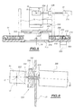
- the assembly 22 for automatic focusing of the device 2 as well as means for fixing the latter to the laser transmitter 20 are shown in the figure 4.
- the automatic focusing assembly 22 has symmetry axial around the vertical axis 16. It has two diverging lenses 60 and 62 fixed, centered on the axis 16, and a converging lens 64, also centered on the axis 16 and being able to move in translation along this axis.
- the two divergent lenses 60 and 62 are arranged in a first tubular mount 66.
- a first part 68 of small section of this mount 66 carries to its free end the divergent lens 60.
- the first cylindrical part 68 of the frame is connected to a second part 70 of larger section, by a transition zone 71 of frustoconical shape.
- the divergent lens 62 is mounted in this second part 70.
- a third part 72 forming a flange is integral with the second cylindrical part 70 at the end thereof opposite the first part 68.
- the mount 66 is mounted in a barrel 74 which has a bore end 76 surrounding the first part of small section 68 of the frame 66 and in which is slidably mounted a sleeve 78 supporting the lens convergent 64.
- the barrel 74 further comprises a bore of larger diameter 80, whose section corresponds to that of the second part 70 of section more important of the mount 66.
- the crown 86 is interposed between the collar 82 and the flange 72 and allows the setting in axial position of the mount 66 carrying the divergent lenses 60.62.
- Three screws 90 for locking the mount 66 arranged at 120 ° are disposed in axial holes 92 formed in the flange 72, extend to inside the crown 86 and are engaged in tapped holes 94 formed in the collar 82 of the barrel 74.
- an axial recess 94 is provided for fixing the laser transmitter 20.
- a base 96 with a diameter smaller than that of the recess 94 and to which the laser emitter 20 is fixed by three screws 98 arranged at 120 °.
- the base 96 is in turn fixed in the bottom of the recess 94 to using three screws 100 with flat heads arranged at 120 ° and engaged in holes axial 102 of larger diameter formed in the base 96 and allowing the radial adjustment of the position of the base and therefore of the laser transmitter 20 relative to the emission axis 16 of the device 2.
- the screws 100 are screwed into the flange 72.
- the recess 94 is delimited by a peripheral rim 104 in which are arranged three screws 106 for radially adjusting the laser transmitter 20.
- the screws 106 arranged at 120 ° each have for example, a knurled head 108 and one end in contact with the lateral surface 110 of the base 96.
- the barrel 74 is surrounded by a magnetic core 112 in which it is for example force fitted.
- the magnetic core 112 is generally cylindrical in shape and is coaxial with the barrel 74 and the mounts 66 and 78 respectively carrying the diverging lenses 60 and 62 and the converging lens 60.
- the magnetic core 112 is in contact by one of its faces with the collar 82 of barrel 74.
- annular groove 114 In the face of the magnetic core 112 opposite the flange 82 is formed an annular groove 114 defining a central projection 116 around which is arranged a coil 118 for actuating a membrane 120 by via a skirt 122 fixed by one of its ends to the membrane 120.
- the flexible membrane 120 is fixed at its periphery to the core magnetic 112 in a conventional manner. It has a hole in the center circular in which the sleeve 78 is engaged and fixed.
- the coil 118 is supplied by a current generator 124 of which the input is connected to the output of a comparator 126 between a generated signal by a PSD type photodiode 128, illuminated by a light beam coming from a light-emitting diode 130 on the path of which is placed the free end of the sleeve 78 carrying the converging lens 64, and a signal corresponding to the distance from spot 52 lighting up scene 4.
- the scanning means represented in FIG. 5 include the galvanometric mirror 42 associated with position control means around orthogonal axes 16 and 44, intersecting at point 0.
- the means for controlling the position of the mirror 42 around the axis vertical 16 allow a sweep in bearing of scene 4 and include a stepper motor 200 associated with a reduction gear 202, arranged under a crown fixed 204 on the periphery thereof.
- Reducer 202 controls rotation around a vertical axis of a pinion 206 passing through the fixed ring 204.
- the pinion 206 drives a movable crown 208 in rotation around the vertical axis 16, by means of a toothed belt 210 bonded to the crown mobile 208.
- the rotation of the movable crown 208 relative to the fixed crown 204 is ensured by a thin ball bearing 212, on a rod, arranged in a groove 213 formed on the periphery of the movable crown 208.
- movable crown 208 On the movable crown 208 are arranged two vertical plates such as plate 15, as well as a plate 223 fixed on these vertical plates.
- the platform 14, described with reference to FIG. 1, includes this plate 223 and the movable crown 208.
- Measuring the rotational displacement around axis 16 of the platform 14 is obtained by means of an optical encoder 214 integral with the crown fixed 204 by means of a fixing ring 216.
- the encoder 214 is an encoder incremental annular, of classical type.
- a cylindrical rim 220 delimiting the axial opening 18 of the plate 223, secured to the movable crown 208.
- the optical encoder 214 is provided with a part mobile 222 blocked on the flange 220 of the plate 223 by fixing screws (not shown). This allows the incremental measurement of the bearing rotation of platform 14.
- the means for controlling the position of the mirror 42 around the axis horizontal 44 allow an elevation scan of scene 4 and include an arm 224 connecting the galvanometric mirror 42 to a scanner galvanometric 226, of conventional type.
- the transmission arm 224 is fixed on the plate 15 by means of first means 228 for adjusting the axis of rotation 44 and allows the transmission around the axis to the mirror 42 44, controlled by the galvanometric scanner 226.
- the galvanometric mirror 42 is both slaved in position around the horizontal axis 44 by means of the galvanometric scanner 226, and slaved in position around the vertical axis 16, by means of the motor 200.
- the frame 19 is fixed to the plate 15, by through second means 229 for adjusting the optical axis 36.
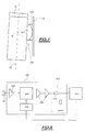
- the first adjustment means 228 shown in FIG. 6 include a cradle 230 formed of a vertical crown portion whose center is positioned on the vertical axis 16, at point 0 located in the center of the mirror galvanometric 42.
- the cradle 230 slides in rotation on a cradle support 232 of the same radius with hollow axis, around a horizontal axis 233, perpendicular to axis 16 and axis 44, parallel to plate 15 and passing through 0.
- the support for cradle 232 is fixed to plate 15.
- the transmission arm 224 is mounted, free to rotate around its axis, inside a sleeve 233 secured to the cradle 230.
- the rotation of the cradle 230 around the horizontal axis 223 in the cradle support 232 causes rotation around this same axis of the assembly constituted by the galvanometric mirror 42, the sleeve 233, the arm 224 and the galvanometric scanner 226, mounted on this cradle 230.
- the second adjustment means 229 shown in top view at FIG. 7 comprises a cradle 234 formed by a portion of the crown horizontal, the center of which is positioned on the vertical axis 16.
- the cradle 234 slides in rotation on a cradle support 236 of same radius, around an axis perpendicular to axis 44 and in the plane containing the vertical axis 16.
- This cradle support 236 is fixed to the plate 15.
- the adjustment means 228 and 229 allow the adjustment of the axis optic 36 and the axis 44 of rotation of the galvanometric mirror 42, by compensation for construction imperfections, such as for example fitting imprecise of the galvanometric mirror 42 on the arm 224 intended to drive it in rotation.
- the scanning means can provide scanning strictly plan.
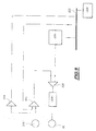
- the photosensitive receiver 46 is associated with means 300 for reducing the dynamics of the signal supplied at the output of this photosensitive receiver 46. These means 300 are integrated into the part electronics 12 of figure 1.
- the photosensitive receiver 46 comprises a photodiode with avalanche providing a current output whose intensity depends directly on the energy of the laser beam it received.
- the means 300 for reducing the dynamics comprise a transimpedance amplifier 302 supplying an electrical signal as an output the voltage is proportional to the intensity of the current supplied as input by the avalanche photodiode. This electrical signal is transmitted to a programmable voltage 304, conventionally associated with means of programming 306.
- the means 300 for reducing the dynamics also include two fixed gain amplifiers 308 arranged in series, at the output of the attenuator 304.
- the number of amplifiers 308 can be different from two.
- the electrical signal output from the fixed gain amplifiers 308 supplies an impedance matching circuit 310, of the conventional type.
- this impedance matching circuit 310 includes two resistors 312, of 50 Ohms each.
- the electrical signal supplied at the output of this adaptation circuit impedance 310 supplies means 314 for measuring the "flight time" of the laser beam implemented on an integrated circuit.
- These measurement means 314 are of the classic type. They are for example of the type described in the French patent n ° 94 11 847 of the French Atomic Energy Commission. They are particularly adapted to provide the programming means with a numerical value of the energy of the signal transmitted to them by the impedance matching circuit 310.
- the programming means 306 determine and regulate the gain of the attenuator 304 to a value inversely proportional to this value digital supplied by the "flight time” measuring means 314, to supply at the output of the attenuator 304, a signal whose voltage is constant whatever or the energy of the laser beam received by photodiode 46.
- a temperature probe 316 of the type conventional is arranged in the vicinity of photodiode 46.
- the voltage corresponding to the temperature measured by this probe 316 is transmitted to a conventional analog-to-digital converter 318, for transmitting a numerical value of this temperature to a 320 computer via a data transmission bus 322.
- the computer 320 transmits via the bus 322, a multiplier coefficient to a digital to analog converter multiplier 324 and a digital setpoint value to a converter digital-analog 326.
- the multiplier coefficient depends on the nature of the temperature 316 and the nature of photodiode 46, but is independent of the temperature measured by probe 316, while the numerical value of setpoint supplied to converter 326 depends on the temperature measured by the probe 316 and corresponds to a predetermined gain value of the photodiode 46, at a given temperature.
- This gain value is provided, for example, by a data table conventionally accessible by the computer 320.
- the digital-analog converter multiplier 324 has a reference input and a digital input. he receives, on its reference input, the voltage corresponding to the temperature measured by probe 316 and on its other digital input, the coefficient multiplier.
- a summing amplifier 328 receives this input voltage as an input. correction as well as a setpoint voltage supplied at the converter output digital-analog 326 and therefore directly related to the digital value of setpoint provided by the computer 320.
- This summing amplifier 328 supplies a voltage of command equal to the sum of the correction voltage and the voltage of setpoint. This voltage value keeps a constant gain in photodiode 46, regardless of temperature variations.
- control voltage is then applied to means 330 supply of photodiode 46, of conventional type, for adjusting the voltage of polarization of the photodiode 46 in accordance with the control voltage supplied by summing amplifier 328.
- spherical coordinates of all the points raised include the distance between the center O of the mirror galvanometric 42 spot 52, an angle measuring the bearing orientation of the laser beam at the exit of the scanning means and an angle measuring the orientation in site of this same laser beam.
- the scanning means are piloted 14,42,200,202,204,206,210,212,224,226, as well as the transmitter 20, so that the spot 52 created on stage 4 by the laser beam successively designates at minus part of the points of the selected subset corresponding to said area of interest.
- This area of interest consists of a set of points which are not not necessarily joined.
- the invention illustrated in the example described previously, creates a three-dimensional lifting device capable of performing measurements over a wide range of distance, compensating for the dynamic effect due to beam energy backscattered inversely proportional to the square of the distance between the spot 52 and the device 2, by a large focal length of the focusing means, while with a reduced bulk.
- a second advantage of the device described above is compensate using a spherical mirror arranged off-axis relative to the laser beam emitted and backscattered, the deformations of the wave surface of the beam caused by the separating plate 32, so that the image of spot 52 at level of the photosensitive receiver 46 is circular.
- Another advantage of the device described above is compensate for the deformations of the wave surface of the beam caused by the spherical mirror 38, on the outward path of the laser beam, between the laser emitter 20 and scene 4, using a prismatic blade 24 disposed between the laser transmitter 20 and the separating blade 32.
- Another advantage of the device described above is allow, thanks to a semi-reflecting patch placed on the blade separator 32, to make measurements, even when the spot is very close to the three-dimensional lifting device.
- Another advantage of the device described above is compensate for the significant dynamic range of the laser beams backscattered by the scene 4, linked to the broadcast indicator of said scene 4, by means of reduction of the dynamic range of the signal output from the photosensitive receiver 46.
- Another advantage of the device described above is to allow a sweep in a field of up to 360 °, while allowing passage of electrical connections between the electronic part and the opto-mechanical part of the device, by means of scanning comprising a platform pierced with an axial opening.
- Another advantage of the device described above is to allow a plan scan of scene 4, and therefore to avoid distortions of a whole of points noted on scene 4, by means of means adjustment servo in position of the galvanometric mirror 42 and the means of adjustment of the laser beam reception axis.
- Another advantage of the device described above is to provide good spatial resolution of the measurement on the target, thanks to a set of automatic focusing of the laser beam emitted by the transmitter 20.
- Another advantage of the device described above is implement a method for designating, in the reference frame of the device 2, an area of interest on scene 4, by means of the laser beam, this area of interest not necessarily accessible by an operator or easily materializable.
- This process can be applied for example to designate the route a cut to be made on a pipe.
Landscapes
- Physics & Mathematics (AREA)
- General Physics & Mathematics (AREA)
- Engineering & Computer Science (AREA)
- Radar, Positioning & Navigation (AREA)
- Remote Sensing (AREA)
- Computer Networks & Wireless Communication (AREA)
- Electromagnetism (AREA)
- Optics & Photonics (AREA)
- Multimedia (AREA)
- Length Measuring Devices By Optical Means (AREA)
- Mechanical Optical Scanning Systems (AREA)
Abstract
Description
- le système optique convergent comprend un miroir sphérique de compensation de déformations de la surface d'onde du faisceau provoquées par la lame séparatrice, ce miroir optique étant disposé hors d'axe par rapport aux faisceaux laser émis et rétrodiffusé ;
- les seconds moyens de mesure comprennent en outre, disposée entre l'émetteur laser et la lame séparatrice, une lame prismatique de compensation des déformations de la surface d'onde du faisceau émis provoquées par le miroir sphérique hors d'axe ;
- les seconds moyens de mesure comprenant en outre des moyens de mesure de l'instant d'émission du faisceau laser et des moyens de mesure de l'instant de réception par le récepteur photosensible du faisceau rétrodiffusé par la scène, les moyens de mesure de l'instant d'émission du faisceau laser comportent une fibre optique recevant une partie du faisceau laser réfléchie hors d'axe par la lame prismatique et la transmettant à un récepteur photosensible ;
- le système optique divergent comprend une lentille divergente disposée sur le trajet du faisceau rétrodiffusé, entre la lame séparatrice et le récepteur photosensible ;
- la lame séparatrice comporte une pastille semi-réfléchissante de réduction de la dynamique de l'énergie du faisceau rétrodiffusé par la scène et reçu par le récepteur photosensible ;
- le récepteur photosensible comprend une photodiode à avalanche associée à des moyens de compensation en température ;
- les moyens de compensation en température comportent une sonde de température et sont des moyens de réglage de la tension de polarisation du récepteur photosensible, en fonction de la température mesurée par cette sonde ;
- les moyens de balayage comprennent un miroir plan et des moyens d'asservissement de la position de ce miroir autour desdits premier et second axes de rotation desdits moyens de balayage ;
- le dispositif comprenant une partie opto-mécanique et une partie électronique, le premier axe de rotation est un axe de rotation en gisement, et les moyens d'asservissement autour de cet axe, comportent une plate-forme entraínée en rotation autour de cet axe par un moteur pas à pas et percée d'une ouverture axiale pour le passage de moyens de connexion électrique entre des éléments de la partie opto-mécanique et des éléments de la partie électronique ;
- la plate-forme est disposée sur une couronne fixe par l'intermédiaire de moyens de roulement à billes sur jonc, disposés entre la plate-forme et la couronne fixe ;
- le moteur pas à pas est disposé sous la couronne fixe en périphérie de celle-ci et est associé à un pignon d'entraínement de la plate-forme en rotation autour du premier axe, par l'intermédiaire d'une courroie crantée portée par la plate-forme ;
- le second axe de rotation est un axe de rotation en site, et les moyens d'asservissement autour de cet axe comportent un bras de transmission, dont l'axe est fixé par rapport à la plate-forme, reliant le miroir à un scanner galvanométrique d'entraínement en rotation du miroir autour dudit second axe ;
- les premiers moyens de mesure comportent un codeur optique incrémental annulaire de mesure de l'orientation du faisceau en gisement, porté par la plate-forme ;
- le codeur optique est solidaire de la couronne fixe et est pourvu d'une partie mobile solidaire de la plate-forme ;
- il comporte en outre un ensemble de focalisation automatique du faisceau laser émis par l'émetteur laser et des moyens de fixation de l'émetteur laser sur l'ensemble ;
- lesdits moyens de fixation comportent une embase portant l'émetteur laser et fixée sur l'ensemble de focalisation automatique au moyen de vis engagées dans des trous axiaux de plus grand diamètre ménagés dans l'embase, et des vis de réglage radial de l'émetteur laser sur l'ensemble de focalisation automatique ;
- l'ensemble de focalisation automatique du faisceau laser comporte au moins une lentille divergente disposée sur l'axe d'émission du faisceau laser, une lentille convergente disposée également sur l'axe d'émission et des moyens de déplacement relatif de la lentille convergente et de la lentille divergente le long de l'axe d'émission ;
- lesdits moyens de déplacement relatif comportent un manchon supportant la lentille convergente autour duquel est fixée une membrane souple et des moyens d'actionnement de la membrane en vue du déplacement dudit manchon le long de l'axe ;
- les moyens d'actionnement de la membrane souple comprennent un générateur de courant et une bobine, alimentée en courant par le générateur de courant, fixée sur la membrane souple et disposée dans l'entrefer d'un noyau magnétique, autour de l'axe d'émission ;
- les moyens d'actionnement de la membrane souple comportent des moyens de comparaison entre la position détectée de la lentille convergente et la position souhaitée de la lentille convergente le long de l'axe comportant des moyens d'activation du générateur de courant en fonction de cette différence ;
- l'ensemble de focalisation automatique comporte des moyens optiques de détection de la position de la lentille convergente sur l'axe d'émission;
- il comporte des moyens de réglage des moyens d'asservissement en position du miroir galvanométrique autour de l'axe de rotation en site et des moyens de réglage de l'axe de réception du faisceau laser autour de l'axe de rotation en gisement ;
- les moyens de réglage des moyens d'asservissement en position du miroir galvanométrique et les moyens de réglage de l'axe de réception du faisceau, comprennent chacun un berceau formé d'une portion de couronne et chacun un support de berceau correspondant dans lequel le berceau glisse en rotation autour de l'axe de ladite couronne ;
- l'axe de rotation du berceau des moyens de réglage des moyens d'asservissement en position du miroir galvanométrique est perpendiculaire à l'axe de rotation en site et à l'axe de rotation en gisement, et l'axe de rotation du berceau des moyens de réglage de l'axe de réception est perpendiculaire à l'axe de rotation en site et dans un plan vertical contenant l'axe de rotation en gisement, lesdits axes de rotation des berceaux étant sécants au centre du miroir;
- il comprend en outre des moyens de réduction de la dynamique du signal fourni en sortie du récepteur photosensible ;
- les moyens de réduction de la dynamique du signal comportent un atténuateur de tension à gain programmable et un ensemble d'amplification à gain fixe en sortie de cet atténuateur ; et
- les seconds moyens de mesure de la distance entre le dispositif et le spot comportent un circuit intégré de mesure du "temps de vol" du faisceau laser.
- le relevé tridimensionnel d'un ensemble de points de la scène ;
- le stockage des coordonnées de l'ensemble de points relevés ;
- la modélisation et/ou la visualisation dudit ensemble de points,
caractérisé en ce qu'il comporte en outre les étapes suivantes :
- la sélection d'un sous-ensemble d'au moins un point dudit ensemble, définissant ladite zone d'intérêt ; et
- le pilotage des moyens de balayage et de l'émetteur pour que le spot créé sur la scène par le faisceau laser désigne successivement au moins une partie des points du sous-ensemble sélectionné correspondant à ladite zone d'intérêt.
- la Fig.1 est une vue schématique de la structure générale d'un dispositif selon l'invention ;
- la Fig.2 représente schématiquement la projection, selon la direction de déplacement d'un faisceau laser, de la surface d'onde de celui-ci, au cours de son trajet aller dans le dispositif de la figure 1 ;
- la Fig.3 représente schématiquement la projection, selon la direction de déplacement d'un faisceau laser, de la surface d'onde de celui-ci, au cours de son trajet retour dans le dispositif de la figure 1 ;
- la Fig.4 est une vue schématique d'un ensemble de focalisation automatique, pour le dispositif de la figure 1 ;
- la Fig.5 est une vue schématique partielle de moyens de balayage du dispositif de la figure 1 ;
- la Fig.6 est une vue schématique de côté de premiers moyens de réglage des moyens de balayage de la figure 3 ;
- la Fig.7 est une vue schématique de dessus de seconds moyens de réglage des moyens de balayage, selon la direction I de la figure 3 ;
- la Fig.8 représente un schéma synoptique de moyens électroniques de réduction de la dynamique d'un signal, pour le dispositif de la figure 1 ; et
- la Fig.9 représente un schéma synoptique de moyens d'asservissement en température d'un récepteur photosensible, pour le dispositif de la figure 1.
- une monture en forme de poutre 19 fixée sur la plate-forme 14 par des plaques telles que la plaque 15 et destinée à soutenir une partie des éléments de la partie opto-mécanique 10 ;
- un émetteur laser 20 de type classique, tel qu'un microlaser, fixé sur cette monture 19 ;
- un ensemble 22 de focalisation automatique d'un faisceau laser émis par l'émetteur laser 20, fixé sur celui-ci ;
- une lame prismatique 24 disposée sur l'axe 26 d'émission d'un faisceau laser par l'émetteur 20, en sortie de l'ensemble 22 de focalisation automatique, et fixée sur la monture 19 ;
- une fibre optique 28 de réception d'une partie du faisceau laser réfléchie hors d'axe par la lame prismatique 24 ;
- un récepteur photosensible 29 de type classique raccordé à la fibre optique 28 ;
- un piège à lumière 30 de type classique fixé sur la monture 19 à une distance prédéterminée de la lame prismatique 24, pour empêcher la réflexion d'une partie du faisceau laser ayant traversé la lame prismatique 24 et reçue par ce piège ;
- une lame séparatrice transparente 32 fixée sur la monture 19 et disposée entre la lame prismatique 24 et le piège à lumière 30, sur l'axe d'émission 26 et inclinée d'environ 45° sur ledit axe ;
- une pastille semi-réfléchissante 34 disposée sur la surface de la lame séparatrice 32 en regard de la lame prismatique 24 et centrée sur l'axe d'émission 26, ladite pastille réfléchissant une partie du faisceau émis par l'émetteur 20 ayant traversé la lame prismatique 24 et transmettant en retour, une partie du faisceau rétrodiffusé par la scène 4, le long d'un axe optique 36 parallèle à l'axe longitudinal de la monture 19 ;
- un miroir sphérique 38 fixé sur la monture 19, disposé hors d'axe par rapport à l'axe optique 36 et réfléchissant un faisceau laser émis par l'émetteur 20 en provenance de la lame séparatrice 32 ou rétrodiffusé par la scène 4 ; le miroir sphérique 38 fait partie d'un système optique convergent.
- un miroir galvanométrique 42 asservi en position angulaire autour d'un axe 44 perpendiculaire à l'axe 16 coupant ce dernier en un point 0 et dont la position sera précisée par la suite. L'axe 44 est fixe par rapport à la plate-forme 14, pour diriger un faisceau laser réfléchi par le miroir sphérique 38 vers la scène 4 et réciproquement pour diriger un faisceau laser rétrodiffusé par la scène 4 vers le miroir sphérique 38 ;
- un récepteur photosensible 46 disposé sur l'axe optique 36, sur le trajet de retour du faisceau laser rétrodiffusé par la scène 4 et transmis par la lame séparatrice 32 ;
- un filtre interférentiel 48 de type classique, disposé sur l'axe optique 36, entre la lame séparatrice 32 et le récepteur photosensible 46, pour filtrer le faisceau rétrodiffusé par la scène 4 avant qu'il n'atteigne le récepteur photosensible 46 ; et
- une lentille divergente 50, disposée sur l'axe optique 36, entre la lame séparatrice 32 et le récepteur photosensible 46, pour former, en association avec le miroir sphérique 38, un téléobjectif afin de réduire la longueur de la voie de réception du faisceau laser rétrodiffusé tout en conservant une distance focale élevée. La lentille divergente 50 fait partie d'un système optique divergent fixe par rapport au système optique convergent et par rapport au récepteur photosensible 46 et au filtre 48. Le système optique convergent est également fixe par rapport au récepteur photosensible 46 et au filtre 48. La lentille divergente 50 et le miroir sphérique 38 sont par conséquent fixes par rapport au récepteur photosensible 46 et au filtre 48.
| Distance (m) | Puissance rétrodiffusée sur le dispositif 2 (µW) | Puissance reçue par le récepteur photosensible 6 (µW) | ||
| Périphérie | Pastille | Total | ||
| 1 | 712,7 | 0 | 0,16 | 0,16 |
| 1,5 | 316,7 | 0 | 0,15 | 0,15 |
| 2 | 178,2 | 0 | 0,14 | 0,14 |
| 3 | 79,2 | 0 | 0,13 | 0,13 |
| 5 | 28,5 | 0 | 0,13 | 0,13 |
| 7 | 14,5 | 0 | 0,13 | 0,13 |
| 10 | 7,1 | 0 | 0,13 | 0,13 |
| 15 | 3,17 | 0 | 0,13 | 0,13 |
| 20 | 1,78 | 0 | 0,13 | 0,13 |
| 30 | 0,79 | 0,11 | 0,07 | 0,18 |
| 40 | 0,45 | 0,17 | 0,04 | 0,21 |
| 50 | 0,29 | 0,2 | 0,03 | 0,23 |
| 60 | 0,2 | 0,16 | 0,02 | 0,18 |
| 70 | 0,15 | 0,12 | 0,01 | 0,13 |
| 80 | 0,111 | 0,09 | 0,01 | 0,1 |
| 90 | 0,088 | 0,07 | 0,01 | 0,08 |
Claims (29)
- Dispositif de relèvement tridimensionnel d'une scène (4), comprenant un émetteur laser (20), des moyens de balayage (14,42,200,202, 204,206,210, 212,224,226) selon des premier et second axes de rotation (16,44) pour balayer la scène (4) à l'aide d'un faisceau laser émis par l'émetteur laser (20), un récepteur photosensible (46) d'une image d'un spot (52) créé par le faisceau laser sur la scène (4), des moyens (38,50) de focalisation du faisceau laser rétrodiffusé par la scène (4) vers le récepteur photosensible (46), des premiers moyens (214,226) de mesure de l'orientation du faisceau à la sortie des moyens de balayage (14,42,200,202,204,206,210,212,224,226), et des seconds moyens (24,28,32,34,48,314) de mesure de la distance entre le dispositif et le spot par télémétrie laser, lesdits seconds moyens de mesure comprenant une lame séparatrice (32) des faisceaux émis et rétrodiffusé par la scène (4), caractérisé en ce que les moyens de focalisation (38,50) comportent un système optique convergent (38) associé à un système optique divergent (50) d'augmentation de la distance focale du système optique convergent formant ainsi un téléobjectif, et en ce que les moyens de balayage (14,42,200,202,204, 206,210,212,224,226) comportent au moins un miroir (42) disposé sur le trajet des faisceaux laser émis et rétrodiffusé, entre les moyens de focalisation (38,50) et la scène (4).
- Dispositif de relèvement tridimensionnel selon la revendication 1, caractérisé en ce que le système optique convergent (38) comprend un miroir sphérique de compensation de déformations de la surface d'onde du faisceau provoquées par la lame séparatrice (32), ce miroir optique étant disposé hors d'axe par rapport au faisceau laser émis et rétrodiffusé.
- Dispositif de relèvement tridimensionnel selon la revendication 1 ou 2, caractérisé en ce que les seconds moyens de mesure comprennent, disposée entre l'émetteur laser (20) et la lame séparatrice (32), une lame prismatique (24) de compensation des déformations de la surface d'onde du faisceau émis provoquées par le miroir sphérique (38) hors d'axe.
- Dispositif de relèvement tridimensionnel selon la revendication 3, dont les seconds moyens de mesure comprennent en outre des moyens (24,28,314) de mesure de l'instant d'émission du faisceau laser et des moyens (48,314) de mesure de l'instant de réception par le récepteur photosensible (46) du faisceau rétrodiffusé par la scène (4), caractérisé en ce que les moyens de mesure de l'instant d'émission du faisceau laser comportent une fibre optique (28) recevant une partie du faisceau laser réfléchie hors d'axe par la lame prismatique (24) et la transmettant à un récepteur photosensible (29).
- Dispositif de relèvement tridimensionnel selon l'une quelconque des revendications 1 à 4, caractérisé en ce que le système optique divergent (50) comprend une lentille divergente disposée sur le trajet du faisceau rétrodiffusé, entre la lame séparatrice (32) et le récepteur photosensible (46).
- Dispositif de relèvement tridimensionnel selon l'une quelconque des revendications 1 à 5, caractérisé en ce que la lame séparatrice (32) comporte une pastille semi-réfléchissante (34) de réduction de la dynamique de l'énergie du faisceau laser rétrodiffusé par la scène (4) et reçu par le récepteur photosensible (46).
- Dispositif de relèvement tridimensionnel selon l'une quelconque des revendications 1 à 6, caractérisé en ce que le récepteur photosensible (46) comprend une photodiode à avalanche, et en ce que cette photodiode est associée à des moyens (330) de compensation en température.
- Dispositif de relèvement tridimensionnel selon la revendication 7, caractérisé en ce que les moyens (330) de compensation en température comportent une sonde de température (316) et sont des moyens de réglage de la tension de polarisation du récepteur photosensible (46), en fonction de la température mesurée par cette sonde (316).
- Dispositif de relèvement tridimensionnel selon l'une quelconque des revendications 1 à 8, caractérisé en ce que les moyens de balayage (14,42,200,202,204,206,210,212,224,226) comprennent un miroir plan (42) et des moyens d'asservissement (14,200,202,206,224,226) de la position de ce miroir autour de chacun desdits premier et second axes de rotation (16,44) desdits moyens de balayage.
- Dispositif de relèvement tridimensionnel selon la revendication 9, comportant une partie opto-mécanique (10) et une partie électronique (12), caractérisé en ce que le premier axe de rotation (16) est un axe de rotation en gisement, et en ce que les moyens d'asservissement (14,200,202,206) autour de cet axe, comportent une plate-forme (14) entraínée en rotation autour de cet axe par un moteur pas à pas (200) et percée d'une ouverture axiale (18) pour le passage de moyens de connexion électrique (18a) entre des éléments de la partie opto-mécanique (10) et des éléments de la partie électronique (12).
- Dispositif de relèvement tridimensionnel selon la revendication 10, caractérisé en ce que la plate-forme (14) est disposée sur une couronne fixe (204) par l'intermédiaire de moyens (212) de roulement à billes sur jonc, disposés entre la plate-forme (14) et la couronne fixe (204).
- Dispositif de relèvement tridimensionnel selon la revendication 11, caractérisé en ce que le moteur pas à pas (200) est disposé sous la couronne fixe (204) en périphérie de celle-ci et est associé à un pignon (206) d'entraínement de la plate-forme (14) en rotation autour du premier axe (16), par l'intermédiaire d'une courroie crantée (210) portée par la plate-forme (14).
- Dispositif de relèvement tridimensionnel selon l'une quelconque des revendications 9 à 12, caractérisé en ce que le second axe de rotation (44) est un axe de rotation en site, et en ce que les moyens d'asservissement (224,226) autour de cet axe comportent un bras de transmission (224), dont l'axe est fixé par rapport à la plate-forme (14), reliant le miroir (42) à un scanner galvanométrique (226) d'entraínement en rotation du miroir (42) autour dudit second axe (44).
- Dispositif de relèvement tridimensionnel selon l'une quelconque des revendications 10 à 13, caractérisé en ce que les premiers moyens de mesure (214,226) comportent un codeur optique incrémental annulaire (214) de mesure de l'orientation du faisceau en gisement, porté par la plate-forme (14).
- Dispositif de relèvement tridimensionnel selon la revendication 14, caractérisé en ce que le codeur optique (214) est solidaire de la couronne fixe (204) et est pourvu d'une partie mobile (222) solidaire de la plate-forme (14).
- Dispositif de relèvement tridimensionnel selon l'une quelconque des revendications 1 à 15, caractérisé en ce qu'il comporte en outre un ensemble (22) de focalisation automatique du faisceau laser émis par l'émetteur laser (20) et des moyens de fixation (96,98,100,108) de l'émetteur laser (20) sur l'ensemble (22).
- Dispositif de relèvement tridimensionnel selon la revendication 16, caractérisé en ce que lesdits moyens de fixation (96,98,100,108) comportent une embase (96) portant l'émetteur laser (20) et fixée sur l'ensemble (22) de focalisation automatique au moyen de vis (100) engagées dans des trous axiaux (102) de plus grand diamètre ménagés dans l'embase (96), et des vis (106) de réglage radial de l'émetteur laser (20) sur l'ensemble (22) de focalisation automatique.
- Dispositif de relèvement tridimensionnel selon l'une quelconque des revendications 16 et 17, caractérisé en ce que l'ensemble (22) de focalisation automatique du faisceau laser comporte au moins une lentille divergente (60,62) disposée sur l'axe d'émission (26) du faisceau laser, une lentille convergente (64) disposée également sur l'axe d'émission (26) et des moyens (78,118,120,122,124,126, 128,130) de déplacement relatif de la lentille convergente (64) et de la lentille divergente (60,62) le long de l'axe d'émission (26).
- Dispositif de relèvement tridimensionnel selon la revendication 18, caractérisé en ce que lesdits moyens (78,118,120,122,124,126, 128,130) de déplacement relatif comportent un manchon (78) supportant la lentille convergente (64) autour duquel est fixée une membrane souple (120) et des moyens (118,124,126,128,130) d'actionnement de la membrane (120) en vue du déplacement dudit manchon (78) le long de l'axe (26).
- Dispositif de relèvement tridimensionnel selon la revendication 19, caractérisé en ce que les moyens (118,124,126,128,130) d'actionnement de la membrane souple (120) comprennent un générateur de courant (124) et une bobine (118), alimentée en courant par le générateur de courant (124), fixée sur la membrane souple (120) et disposée dans l'entrefer d'un noyau magnétique (112), autour de l'axe d'émission (26).
- Dispositif de relèvement tridimensionnel selon la revendication 19 ou 20, caractérisé en ce que les moyens (118,124,126,128,130) d'actionnement de la membrane souple (120) comportent des moyens (126) de comparaison entre la position détectée de la lentille convergente (64) et la position souhaitée de la lentille convergente (64) le long de l'axe (26) comportant des moyens d'activation du générateur de courant (124) en fonction de cette différence.
- Dispositif de relèvement tridimensionnel selon l'une quelconque des revendications 16 à 21, caractérisé en ce que l'ensemble (22) de focalisation automatique comporte des moyens (128,130) optiques de détection de la position de la lentille convergente (64) sur l'axe d'émission (26).
- Dispositif de relèvement tridimensionnel selon l'une quelconque des revendications 9 à 22, caractérisé en ce qu'il comporte des moyens de réglage (228) des moyens d'asservissement en position du miroir galvanométrique (42) autour de l'axe (44) de rotation en site et des moyens de réglage (229) de l'axe (36) de réception du faisceau laser autour de l'axe (16) de rotation en gisement.
- Dispositif de relèvement tridimensionnel selon la revendication 23, caractérisé en ce que les moyens (228) de réglage des moyens d'asservissement en position du miroir galvanométrique (42) et les moyens (229) de réglage de l'axe (36) de réception du faisceau, comprennent chacun un berceau (230,234) formé d'une portion de couronne et chacun un support de berceau correspondant (232,236) dans lequel le berceau glisse en rotation autour de l'axe de ladite couronne.
- Dispositif de relèvement tridimensionnel selon la revendication 24, caractérisé en ce que l'axe de rotation du berceau (230) des moyens de réglage (228) des moyens d'asservissement en position du miroir galvanométrique est perpendiculaire à l'axe (44) de rotation en site et à l'axe (16) de rotation en gisement, et en ce que l'axe de rotation du berceau (234) des moyens de réglage (229) de l'axe (36) de réception est perpendiculaire à l'axe (44) de rotation en site et dans un plan vertical contenant l'axe (16) de rotation en gisement, lesdits axes de rotation des berceaux (230,234) étant sécants au centre du miroir (42).
- Dispositif de relèvement tridimensionnel selon l'une quelconque des revendications 1 à 25, caractérisé en ce qu'il comprend en outre des moyens (300) de réduction de la dynamique du signal fourni en sortie du récepteur photosensible (46).
- Dispositif de relèvement tridimensionnel selon la revendication 26, caractérisé en ce que les moyens (300) de réduction de la dynamique du signal comportent un atténuateur de tension (304) à gain programmable et un ensemble (308) d'amplification à gain fixe en sortie de cet atténuateur (304).
- Dispositif de relèvement tridimensionnel selon l'une quelconque des revendications 1 à 27, caractérisé en ce que les seconds moyens (24,28,32,34,48,314) de mesure de la distance entre le dispositif et le spot comportent un circuit intégré (314) de mesure du "temps de vol" du faisceau laser.
- Procédé de désignation d'une zone d'intérêt sur une scène (4) mis en oeuvre dans un dispositif de relèvement tridimensionnel selon l'une quelconque des revendications 1 à 28, comportant les étapes suivantes :le relevé tridimensionnel d'un ensemble de points de la scène (4) ;le stockage (12) des coordonnées de l'ensemble de points relevés ;la modélisation et/ou visualisation dudit ensemble de points ;
caractérisé en ce qu'il comporte en outre les étapes suivantes :la sélection d'un sous-ensemble d'au moins un point dudit ensemble, définissant ladite zone d'intérêt ; etle pilotage des moyens de balayage (14,42,200,202,204,206,210, 212, 224,226) et de l'émetteur (20) pour que le spot (52) créé sur la scène (4) par le faisceau laser désigne successivement au moins une partie des points du sous-ensemble sélectionné correspondant à ladite zone d'intérêt.
Applications Claiming Priority (2)
| Application Number | Priority Date | Filing Date | Title |
|---|---|---|---|
| FR0015232A FR2817339B1 (fr) | 2000-11-24 | 2000-11-24 | Dispositif de relevement tridimensionnel d'une scene a emission laser |
| FR0015232 | 2000-11-24 |
Publications (2)
| Publication Number | Publication Date |
|---|---|
| EP1209441A1 true EP1209441A1 (fr) | 2002-05-29 |
| EP1209441B1 EP1209441B1 (fr) | 2007-12-26 |
Family
ID=8856866
Family Applications (1)
| Application Number | Title | Priority Date | Filing Date |
|---|---|---|---|
| EP01403013A Expired - Lifetime EP1209441B1 (fr) | 2000-11-24 | 2001-11-23 | Dispositif de relèvement tridimensionnel d'une scène à émission laser |
Country Status (6)
| Country | Link |
|---|---|
| US (1) | US7030968B2 (fr) |
| EP (1) | EP1209441B1 (fr) |
| JP (1) | JP4065681B2 (fr) |
| DE (1) | DE60132066T2 (fr) |
| ES (1) | ES2296721T3 (fr) |
| FR (1) | FR2817339B1 (fr) |
Cited By (4)
| Publication number | Priority date | Publication date | Assignee | Title |
|---|---|---|---|---|
| FR2940831A1 (fr) * | 2009-01-06 | 2010-07-09 | Peugeot Citroen Automobiles Sa | Dispositif d'eclairage d'une entite d'au moins un vehicule automobile |
| ES2380531A1 (es) * | 2009-07-17 | 2012-05-16 | Elio Berhanyer, S.L. | Escáner tridimensional sin contacto para la medición de objetos. |
| US9638520B2 (en) | 2011-03-18 | 2017-05-02 | Robert Bosch Gmbh | Measuring apparatus and measuring device for measuring a target object in a multidimensional manner |
| CN112764184A (zh) * | 2019-10-21 | 2021-05-07 | 株式会社三丰 | 光学装置及光学式测量机 |
Families Citing this family (118)
| Publication number | Priority date | Publication date | Assignee | Title |
|---|---|---|---|---|
| DE19930815B4 (de) * | 1999-07-01 | 2008-04-17 | Carl Zeiss Jena Gmbh | Anordnung zur Abblendung von Strahlung bei Projektoren und/oder Beleuchtungseinrichtungen |
| US6705727B1 (en) | 2002-12-30 | 2004-03-16 | Bausch & Lomb Incorporated | Mechanism for rotationally moving a mirror |
| WO2004061389A1 (fr) * | 2002-12-31 | 2004-07-22 | D3D, L.P. | Systeme numeriseur au laser pour applications dentaires |
| WO2004085956A2 (fr) | 2003-03-24 | 2004-10-07 | D3D, L.P. | Systeme numeriseur laser pour applications dentaires |
| AU2004237243B2 (en) | 2003-05-05 | 2010-11-11 | D4D Technologies, Llc | Optical coherence tomography imaging |
| US7359041B2 (en) * | 2003-09-04 | 2008-04-15 | Avago Technologies Ecbu Ip Pte Ltd | Method and system for optically tracking a target using a triangulation technique |
| US7272264B2 (en) * | 2003-09-11 | 2007-09-18 | International Business Machines Corporation | System and method for hole filling in 3D models |
| CA2538162C (fr) | 2003-09-17 | 2010-02-02 | D4D Technologies, L.P. | Numerisation tridimensionnelle grande vitesse de lignes multiples |
| DE10361870B4 (de) * | 2003-12-29 | 2006-05-04 | Faro Technologies Inc., Lake Mary | Laserscanner und Verfahren zum optischen Abtasten und Vermessen einer Umgebung des Laserscanners |
| DE502005009867D1 (de) * | 2004-05-04 | 2010-08-19 | Leica Geosystems Ag | Zielerfassungsgerät |
| US20060232762A1 (en) * | 2005-04-15 | 2006-10-19 | Specialty Minerals (Michigan) Inc. | Optical element, measuring apparatus and measuring method |
| US20060232763A1 (en) * | 2005-04-15 | 2006-10-19 | Specialty Minerals (Michigan) Inc. | Optical element, measuring apparatus and measuring method |
| US7259838B2 (en) * | 2005-06-17 | 2007-08-21 | Specialty Minerals (Michigan) Inc. | Optical beam separation element, measuring apparatus and method of measuring |
| DE102005043931A1 (de) * | 2005-09-15 | 2007-03-29 | Fraunhofer-Gesellschaft zur Förderung der angewandten Forschung e.V. | Laserscanner |
| US8050863B2 (en) * | 2006-03-16 | 2011-11-01 | Gray & Company, Inc. | Navigation and control system for autonomous vehicles |
| DE202006005643U1 (de) * | 2006-03-31 | 2006-07-06 | Faro Technologies Inc., Lake Mary | Vorrichtung zum dreidimensionalen Erfassen eines Raumbereichs |
| USRE46672E1 (en) | 2006-07-13 | 2018-01-16 | Velodyne Lidar, Inc. | High definition LiDAR system |
| US20090323739A1 (en) * | 2006-12-22 | 2009-12-31 | Uv Tech Systems | Laser optical system |
| JP2008249375A (ja) * | 2007-03-29 | 2008-10-16 | Topcon Corp | 3次元位置測定装置 |
| US7663736B2 (en) * | 2007-04-10 | 2010-02-16 | Sanyo Electric Co., Ltd. | Laser radar driving apparatus |
| EP1990656A1 (fr) * | 2007-05-07 | 2008-11-12 | Sick Ag | Atténuateur avec diodes PIN pour appareil de mesure de distances optique |
| FR2923314B1 (fr) * | 2007-11-02 | 2010-09-03 | Commissariat Energie Atomique | Procede de detection d'une impulsion lumineuse reflechie sur un objet pour determiner la distance de l'objet, capteur et dispositif de mise en oeuvre. |
| JP5181628B2 (ja) * | 2007-11-12 | 2013-04-10 | 株式会社デンソーウェーブ | レーザレーダ装置 |
| WO2009115122A1 (fr) * | 2008-03-20 | 2009-09-24 | Trimble Ab | Dispositif à balayage géodésique avec rendement accru |
| US7920262B2 (en) * | 2008-09-17 | 2011-04-05 | The United States Of America As Represented By The Secretary Of The Army | Systems for measuring backscattered light using rotating mirror |
| US7841232B2 (en) * | 2008-10-02 | 2010-11-30 | Ford Global Technologies, Llc | Method of dynamically measuring stiffness of a wheel and tire assembly |
| KR100930620B1 (ko) * | 2008-10-20 | 2009-12-09 | 에이티아이 주식회사 | 대구경 오목거울을 이용한 삼각측량장치 |
| DE102009010465B3 (de) * | 2009-02-13 | 2010-05-27 | Faro Technologies, Inc., Lake Mary | Laserscanner |
| DE102009015920B4 (de) | 2009-03-25 | 2014-11-20 | Faro Technologies, Inc. | Vorrichtung zum optischen Abtasten und Vermessen einer Umgebung |
| US9551575B2 (en) | 2009-03-25 | 2017-01-24 | Faro Technologies, Inc. | Laser scanner having a multi-color light source and real-time color receiver |
| DE102009035337A1 (de) | 2009-07-22 | 2011-01-27 | Faro Technologies, Inc., Lake Mary | Verfahren zum optischen Abtasten und Vermessen eines Objekts |
| DE102009035336B3 (de) | 2009-07-22 | 2010-11-18 | Faro Technologies, Inc., Lake Mary | Vorrichtung zum optischen Abtasten und Vermessen einer Umgebung |
| DE102009040837A1 (de) * | 2009-09-10 | 2011-03-17 | Carl Zeiss Ag | Vorrichtungen und Verfahren zur Positionsbestimmung und Oberflächenvermessung |
| TWI399525B (zh) * | 2009-10-09 | 2013-06-21 | Micro Star Int Co Ltd | 距離量測裝置 |
| DE102009055989B4 (de) | 2009-11-20 | 2017-02-16 | Faro Technologies, Inc. | Vorrichtung zum optischen Abtasten und Vermessen einer Umgebung |
| US9113023B2 (en) | 2009-11-20 | 2015-08-18 | Faro Technologies, Inc. | Three-dimensional scanner with spectroscopic energy detector |
| DE102009055988B3 (de) | 2009-11-20 | 2011-03-17 | Faro Technologies, Inc., Lake Mary | Vorrichtung zum optischen Abtasten und Vermessen einer Umgebung |
| US9529083B2 (en) | 2009-11-20 | 2016-12-27 | Faro Technologies, Inc. | Three-dimensional scanner with enhanced spectroscopic energy detector |
| US9210288B2 (en) | 2009-11-20 | 2015-12-08 | Faro Technologies, Inc. | Three-dimensional scanner with dichroic beam splitters to capture a variety of signals |
| DE102009057101A1 (de) | 2009-11-20 | 2011-05-26 | Faro Technologies, Inc., Lake Mary | Vorrichtung zum optischen Abtasten und Vermessen einer Umgebung |
| US9879976B2 (en) | 2010-01-20 | 2018-01-30 | Faro Technologies, Inc. | Articulated arm coordinate measurement machine that uses a 2D camera to determine 3D coordinates of smoothly continuous edge features |
| US20110178765A1 (en) | 2010-01-20 | 2011-07-21 | Faro Technologies, Inc. | Multi-functional coordinate measurement machines |
| US9628775B2 (en) | 2010-01-20 | 2017-04-18 | Faro Technologies, Inc. | Articulated arm coordinate measurement machine having a 2D camera and method of obtaining 3D representations |
| US9163922B2 (en) | 2010-01-20 | 2015-10-20 | Faro Technologies, Inc. | Coordinate measurement machine with distance meter and camera to determine dimensions within camera images |
| US9607239B2 (en) | 2010-01-20 | 2017-03-28 | Faro Technologies, Inc. | Articulated arm coordinate measurement machine having a 2D camera and method of obtaining 3D representations |
| DE102010020925B4 (de) | 2010-05-10 | 2014-02-27 | Faro Technologies, Inc. | Verfahren zum optischen Abtasten und Vermessen einer Umgebung |
| DE102010032723B3 (de) | 2010-07-26 | 2011-11-24 | Faro Technologies, Inc. | Vorrichtung zum optischen Abtasten und Vermessen einer Umgebung |
| DE102010032726B3 (de) | 2010-07-26 | 2011-11-24 | Faro Technologies, Inc. | Vorrichtung zum optischen Abtasten und Vermessen einer Umgebung |
| DE102010032725B4 (de) | 2010-07-26 | 2012-04-26 | Faro Technologies, Inc. | Vorrichtung zum optischen Abtasten und Vermessen einer Umgebung |
| DE102010033561B3 (de) | 2010-07-29 | 2011-12-15 | Faro Technologies, Inc. | Vorrichtung zum optischen Abtasten und Vermessen einer Umgebung |
| US9168654B2 (en) | 2010-11-16 | 2015-10-27 | Faro Technologies, Inc. | Coordinate measuring machines with dual layer arm |
| EP2469294A1 (fr) * | 2010-12-23 | 2012-06-27 | André Borowski | Appareil d'imagerie 2D/3D en temps réel et procédés d'imagerie correspondants |
| EP2469295A1 (fr) * | 2010-12-23 | 2012-06-27 | André Borowski | Appareil d'imagerie en temps réel de paysage en 3D et procédés d'imagerie |
| DE102011105376A1 (de) * | 2011-06-20 | 2012-12-20 | Hochschule Bochum | Vorrichtung und Verfahren zur Richtungskalibrierung eines Polarmessgerätes |
| DE102011107594A1 (de) * | 2011-07-16 | 2013-01-17 | Valeo Schalter Und Sensoren Gmbh | Optische Messvorrichtung für ein Fahrzeug, Fahrerassistenzeinrichtung mit einer derartigen Messvorrichtung sowie Fahrzeug mit einer entsprechenden Messvorrichtung |
| WO2013096704A1 (fr) * | 2011-12-20 | 2013-06-27 | Sadar 3D, Inc. | Systèmes, appareil et procédés d'acquisition et d'utilisation de données d'image |
| DE102012100609A1 (de) | 2012-01-25 | 2013-07-25 | Faro Technologies, Inc. | Vorrichtung zum optischen Abtasten und Vermessen einer Umgebung |
| US8997362B2 (en) | 2012-07-17 | 2015-04-07 | Faro Technologies, Inc. | Portable articulated arm coordinate measuring machine with optical communications bus |
| JP2014052366A (ja) | 2012-08-06 | 2014-03-20 | Ricoh Co Ltd | 光計測装置、車両 |
| DE102012107544B3 (de) | 2012-08-17 | 2013-05-23 | Faro Technologies, Inc. | Vorrichtung zum optischen Abtasten und Vermessen einer Umgebung |
| GB2521312B (en) | 2012-09-06 | 2016-07-06 | Faro Tech Inc | Laser scanner with additional sensing device |
| GB2522142A (en) | 2012-09-14 | 2015-07-15 | Faro Tech Inc | Laser scanner with dynamical adjustment of angular scan velocity |
| US10067231B2 (en) | 2012-10-05 | 2018-09-04 | Faro Technologies, Inc. | Registration calculation of three-dimensional scanner data performed between scans based on measurements by two-dimensional scanner |
| US9513107B2 (en) | 2012-10-05 | 2016-12-06 | Faro Technologies, Inc. | Registration calculation between three-dimensional (3D) scans based on two-dimensional (2D) scan data from a 3D scanner |
| DE102012109481A1 (de) | 2012-10-05 | 2014-04-10 | Faro Technologies, Inc. | Vorrichtung zum optischen Abtasten und Vermessen einer Umgebung |
| US9823351B2 (en) | 2012-12-18 | 2017-11-21 | Uber Technologies, Inc. | Multi-clad fiber based optical apparatus and methods for light detection and ranging sensors |
| EP2759845B1 (fr) * | 2013-01-28 | 2015-09-16 | Sick Ag | Capteur optoélectronique |
| US9470520B2 (en) | 2013-03-14 | 2016-10-18 | Apparate International C.V. | LiDAR scanner |
| JP6045963B2 (ja) * | 2013-04-05 | 2016-12-14 | 日立マクセル株式会社 | 光測距装置 |
| CN104442552B (zh) * | 2013-09-13 | 2018-03-09 | 富泰华工业(深圳)有限公司 | 车辆装置及其防撞系统 |
| CA2931055C (fr) | 2013-11-22 | 2022-07-12 | Ottomotto Llc | Etalonnage d'analyseur lidar |
| US9869753B2 (en) | 2014-08-15 | 2018-01-16 | Quanergy Systems, Inc. | Three-dimensional-mapping two-dimensional-scanning lidar based on one-dimensional-steering optical phased arrays and method of using same |
| WO2016050701A1 (fr) * | 2014-09-29 | 2016-04-07 | Politecnico Di Milano | Procédé et dispositif pour détecter la forme de voiles |
| US10036803B2 (en) | 2014-10-20 | 2018-07-31 | Quanergy Systems, Inc. | Three-dimensional lidar sensor based on two-dimensional scanning of one-dimensional optical emitter and method of using same |
| DE102015200224A1 (de) * | 2015-01-09 | 2016-07-14 | Robert Bosch Gmbh | 3D-LIDAR-Sensor |
| US9970781B2 (en) * | 2015-03-03 | 2018-05-15 | West Virginia University | Apparatus for three-axis IMU calibration with a single-axis rate table |
| DE102015105264A1 (de) * | 2015-04-08 | 2016-10-13 | Sick Ag | Optoelektronischer Sensor und Verfahren zur Transmissionsüberwachung einer Frontscheibe |
| US9747519B2 (en) | 2015-04-24 | 2017-08-29 | Microsoft Technology Licensing, Llc | Classifying ambiguous image data |
| DE102015122844A1 (de) | 2015-12-27 | 2017-06-29 | Faro Technologies, Inc. | 3D-Messvorrichtung mit Batteriepack |
| US10627490B2 (en) | 2016-01-31 | 2020-04-21 | Velodyne Lidar, Inc. | Multiple pulse, LIDAR based 3-D imaging |
| CA3017735C (fr) | 2016-03-19 | 2023-03-14 | Velodyne Lidar, Inc. | Eclairage et detection integres pour imagerie 3d basee sur lidar |
| EP3239927B1 (fr) * | 2016-04-25 | 2021-04-07 | ALSTOM Transport Technologies | Procédé d'inspection de complétude utilisant un ensemble de mesure actif |
| US9964437B2 (en) | 2016-05-03 | 2018-05-08 | Datalogic IP Tech, S.r.l. | Laser scanner with reduced internal optical reflection comprising a light detector disposed between an interference filter and a collecting mirror |
| US11585905B2 (en) | 2016-05-03 | 2023-02-21 | Datalogic Ip Tech S.R.L. | Laser scanner |
| US10048120B2 (en) * | 2016-05-03 | 2018-08-14 | Datalogic IP Tech, S.r.l. | Laser scanner and optical system |
| WO2017210418A1 (fr) | 2016-06-01 | 2017-12-07 | Velodyne Lidar, Inc. | Lidar à balayage à pixels multiples |
| US10061021B2 (en) | 2016-07-06 | 2018-08-28 | Datalogic IP Tech, S.r.l. | Clutter filter configuration for safety laser scanner |
| DE102016218291A1 (de) | 2016-09-23 | 2018-03-29 | Robert Bosch Gmbh | Verfahren zur kontaktfreien Ermittlung einer zweidimensionalen Temperaturin-formation sowie Infrarot-Messsystem |
| DE102016218295A1 (de) | 2016-09-23 | 2018-03-29 | Robert Bosch Gmbh | Verfahren zur kontaktfreien Ermittlung einer zweidimensionalen Temperaturin-formation sowie Infrarot-Messsystem |
| USD871412S1 (en) * | 2016-11-21 | 2019-12-31 | Datalogic Ip Tech S.R.L. | Optical scanner |
| JP7290571B2 (ja) | 2017-03-31 | 2023-06-13 | ベロダイン ライダー ユーエスエー,インコーポレイテッド | 統合化されたlidar照明出力制御 |
| JP2020519881A (ja) | 2017-05-08 | 2020-07-02 | ベロダイン ライダー, インク. | Lidarデータ収集及び制御 |
| US11294035B2 (en) | 2017-07-11 | 2022-04-05 | Nuro, Inc. | LiDAR system with cylindrical lenses |
| US11061116B2 (en) | 2017-07-13 | 2021-07-13 | Nuro, Inc. | Lidar system with image size compensation mechanism |
| US11009868B2 (en) | 2017-07-20 | 2021-05-18 | Nuro, Inc. | Fleet of autonomous vehicles with lane positioning and platooning behaviors |
| US11467574B2 (en) | 2017-07-20 | 2022-10-11 | Nuro, Inc. | Infrastructure monitoring system on autonomous vehicles |
| EP3659080A4 (fr) | 2017-07-28 | 2021-04-21 | Nuro, Inc. | Système et mécanisme de vente incitative de produits sur des véhicules autonomes |
| JPWO2019031328A1 (ja) * | 2017-08-07 | 2020-08-06 | パイオニア株式会社 | 光学装置 |
| EP3701282A4 (fr) | 2017-10-26 | 2021-06-16 | Shenzhen Genorivision Technology Co. Ltd. | Scanner à lumière |
| US10824862B2 (en) | 2017-11-14 | 2020-11-03 | Nuro, Inc. | Three-dimensional object detection for autonomous robotic systems using image proposals |
| US11294041B2 (en) * | 2017-12-08 | 2022-04-05 | Velodyne Lidar Usa, Inc. | Systems and methods for improving detection of a return signal in a light ranging and detection system |
| US11971507B2 (en) | 2018-08-24 | 2024-04-30 | Velodyne Lidar Usa, Inc. | Systems and methods for mitigating optical crosstalk in a light ranging and detection system |
| KR102508988B1 (ko) * | 2018-09-04 | 2023-03-09 | 현대모비스 주식회사 | 라이다 센싱장치 |
| US10712434B2 (en) | 2018-09-18 | 2020-07-14 | Velodyne Lidar, Inc. | Multi-channel LIDAR illumination driver |
| US11082010B2 (en) | 2018-11-06 | 2021-08-03 | Velodyne Lidar Usa, Inc. | Systems and methods for TIA base current detection and compensation |
| US11885958B2 (en) | 2019-01-07 | 2024-01-30 | Velodyne Lidar Usa, Inc. | Systems and methods for a dual axis resonant scanning mirror |
| US12061263B2 (en) | 2019-01-07 | 2024-08-13 | Velodyne Lidar Usa, Inc. | Systems and methods for a configurable sensor system |
| US10613203B1 (en) | 2019-07-01 | 2020-04-07 | Velodyne Lidar, Inc. | Interference mitigation for light detection and ranging |
| WO2021016801A1 (fr) * | 2019-07-29 | 2021-02-04 | 深圳市速腾聚创科技有限公司 | Système optique de réception, module de réception de lumière laser, radar laser et procédé de réglage de lumière |
| US11964627B2 (en) | 2019-09-30 | 2024-04-23 | Nuro, Inc. | Methods and apparatus for supporting compartment inserts in autonomous delivery vehicles |
| US11662562B2 (en) * | 2020-02-09 | 2023-05-30 | Kla Corporation | Broadband illumination tuning |
| CN115088001A (zh) | 2020-03-23 | 2022-09-20 | 纽诺有限公司 | 用于自主递送的方法和装置 |
| CN114594447B (zh) * | 2020-12-04 | 2025-04-11 | 浙江禾秒科技有限公司 | 装调设备及其装调方法 |
| CN113779793B (zh) * | 2021-09-10 | 2023-09-26 | 电子科技大学 | 一种基于射线追踪的激光选区熔化的热源建模方法 |
| WO2023249723A1 (fr) * | 2022-06-22 | 2023-12-28 | Airhive Inc | Véhicule aérien sans pilote (uav) destiné à faciliter des livraisons aériennes de marchandises |
| US20260001667A1 (en) * | 2022-06-22 | 2026-01-01 | Airhive Inc. | Unmanned aerial vehicle (uav) for facilitating aerial deliveries of cargo |
| CN116203535B (zh) * | 2023-04-28 | 2023-08-22 | 枣庄科技职业学院 | 一种计算机辅助光学扫描三维成像系统 |
| JP2025148218A (ja) * | 2024-03-25 | 2025-10-07 | 富士フイルム株式会社 | 計測装置及び方法 |
Citations (6)
| Publication number | Priority date | Publication date | Assignee | Title |
|---|---|---|---|---|
| US4707610A (en) * | 1985-07-03 | 1987-11-17 | Siscan Systems, Inc. | Method and apparatus for measuring surface profiles |
| US4710621A (en) * | 1985-01-11 | 1987-12-01 | U.S. Philips Corporation | Opto-mechanical scanner with fixed-field ranging device |
| US5237331A (en) * | 1992-05-08 | 1993-08-17 | Henderson Sammy W | Eyesafe coherent laser radar for velocity and position measurements |
| EP0599542A1 (fr) * | 1992-11-27 | 1994-06-01 | Xerox Corporation | Système électique deux éléments pour la compensation d'aberration focus dans des systèmes de balayage à laser |
| US5988862A (en) * | 1996-04-24 | 1999-11-23 | Cyra Technologies, Inc. | Integrated system for quickly and accurately imaging and modeling three dimensional objects |
| US6115114A (en) * | 1996-04-12 | 2000-09-05 | Holometrics, Inc. | Laser scanning system and applications |
Family Cites Families (4)
| Publication number | Priority date | Publication date | Assignee | Title |
|---|---|---|---|---|
| DE2818942C2 (de) * | 1978-04-28 | 1986-03-27 | Zellweger Uster Ag, Uster | Verfahren zur Raumüberwachung und Vorrichtung zur Durchführung des Verfahrens |
| DE3570529D1 (en) * | 1984-03-05 | 1989-06-29 | Siemens Ag | Optical system for the simultaneous reception of thermal and laser radiation |
| FR2610400B1 (fr) * | 1987-02-04 | 1989-04-28 | Paramythioti Michel | Procede et dispositif de relevement tridimensionnel |
| JPH1164518A (ja) * | 1997-08-12 | 1999-03-05 | Mitsubishi Electric Corp | 車両用光レーダ装置 |
-
2000
- 2000-11-24 FR FR0015232A patent/FR2817339B1/fr not_active Expired - Lifetime
-
2001
- 2001-11-22 JP JP2001357650A patent/JP4065681B2/ja not_active Expired - Lifetime
- 2001-11-23 DE DE60132066T patent/DE60132066T2/de not_active Expired - Lifetime
- 2001-11-23 EP EP01403013A patent/EP1209441B1/fr not_active Expired - Lifetime
- 2001-11-23 ES ES01403013T patent/ES2296721T3/es not_active Expired - Lifetime
- 2001-11-23 US US09/990,309 patent/US7030968B2/en not_active Expired - Lifetime
Patent Citations (6)
| Publication number | Priority date | Publication date | Assignee | Title |
|---|---|---|---|---|
| US4710621A (en) * | 1985-01-11 | 1987-12-01 | U.S. Philips Corporation | Opto-mechanical scanner with fixed-field ranging device |
| US4707610A (en) * | 1985-07-03 | 1987-11-17 | Siscan Systems, Inc. | Method and apparatus for measuring surface profiles |
| US5237331A (en) * | 1992-05-08 | 1993-08-17 | Henderson Sammy W | Eyesafe coherent laser radar for velocity and position measurements |
| EP0599542A1 (fr) * | 1992-11-27 | 1994-06-01 | Xerox Corporation | Système électique deux éléments pour la compensation d'aberration focus dans des systèmes de balayage à laser |
| US6115114A (en) * | 1996-04-12 | 2000-09-05 | Holometrics, Inc. | Laser scanning system and applications |
| US5988862A (en) * | 1996-04-24 | 1999-11-23 | Cyra Technologies, Inc. | Integrated system for quickly and accurately imaging and modeling three dimensional objects |
Cited By (4)
| Publication number | Priority date | Publication date | Assignee | Title |
|---|---|---|---|---|
| FR2940831A1 (fr) * | 2009-01-06 | 2010-07-09 | Peugeot Citroen Automobiles Sa | Dispositif d'eclairage d'une entite d'au moins un vehicule automobile |
| ES2380531A1 (es) * | 2009-07-17 | 2012-05-16 | Elio Berhanyer, S.L. | Escáner tridimensional sin contacto para la medición de objetos. |
| US9638520B2 (en) | 2011-03-18 | 2017-05-02 | Robert Bosch Gmbh | Measuring apparatus and measuring device for measuring a target object in a multidimensional manner |
| CN112764184A (zh) * | 2019-10-21 | 2021-05-07 | 株式会社三丰 | 光学装置及光学式测量机 |
Also Published As
| Publication number | Publication date |
|---|---|
| FR2817339A1 (fr) | 2002-05-31 |
| FR2817339B1 (fr) | 2004-05-14 |
| ES2296721T3 (es) | 2008-05-01 |
| DE60132066D1 (de) | 2008-02-07 |
| EP1209441B1 (fr) | 2007-12-26 |
| JP2002257526A (ja) | 2002-09-11 |
| US20020143506A1 (en) | 2002-10-03 |
| JP4065681B2 (ja) | 2008-03-26 |
| US7030968B2 (en) | 2006-04-18 |
| DE60132066T2 (de) | 2008-12-18 |
Similar Documents
| Publication | Publication Date | Title |
|---|---|---|
| EP1209441B1 (fr) | Dispositif de relèvement tridimensionnel d'une scène à émission laser | |
| EP0597771B1 (fr) | Dispositif de contrÔle du centrage d'un faisceau lumineux, application à l'introduction de ce faisceau dans une fibre optique | |
| EP0291394A1 (fr) | Capteur de déplacement à fibres optiques décalées | |
| FR2534017A1 (fr) | Procede et appareil pour realiser l'alignement statique d'arbres et pour controler cet alignement | |
| FR2553910A1 (fr) | Detecteur thermoelectrique d'alignement d'un faisceau laser et dispositif d'asservissement utilisant ce detecteur, pour l'alignement automatique d'un faisceau laser | |
| FR2559577A1 (fr) | Procede de mesure par trace polygonal et dispositif de mesure | |
| FR2559541A1 (fr) | Procede et dispositif de surveillance et/ou de commande d'une machine de creusement et notamment d'une machine ponctuelle | |
| FR2652166A1 (fr) | Dispositif d'harmonisation automatique pour un systeme optronique. | |
| FR2572515A1 (fr) | Dispositif de detection de position | |
| FR2490809A1 (fr) | Dispositif permettant de determiner la structure et/ou la forme de la surface d'un objet | |
| EP0702246A1 (fr) | Dispositif embarquable de mesure de rétrodiffusion de lumière | |
| FR2716722A1 (fr) | Système interférométrique de détection et de localisation de défauts réflecteurs de structures guidant la lumière. | |
| EP0300934A1 (fr) | Projecteur de rayon laser et dispositif de mesure à distance comportant au moins deux de ces projecteurs | |
| WO2015040117A1 (fr) | Telescope comportant des moyens internes de reglage au plan focal | |
| EP0111441A1 (fr) | Appareil de mesure de l'indice de réfraction d'une fibre optique | |
| FR2612628A1 (fr) | Dispositif de mesure par interferometrie laser | |
| EP1195575A1 (fr) | Dispositif et procédé de détermination de coordonnées surfacique et leurs utilisations et procédé de positionnement d'un ensemble emetteur laser-récepteur | |
| EP3642644B1 (fr) | Dispositif pour le diagnostic de systemes optroniques et procede associe | |
| CA2680015A1 (fr) | Systeme de metrologie optique | |
| FR2662244A1 (fr) | Dispositif de mesure du pointage d'un rayonnement laser. | |
| EP0336793B1 (fr) | Dispositif de repérage d'un objet, utilisant un balayage de celui-ci par un faisceau lumineux | |
| FR2706628A1 (fr) | Dispositif de localisation de sources de rayonnement, utilisant des moyens de détection à collimation variable. | |
| FR2632723A1 (fr) | Systeme de detection pour photometre | |
| WO2024133165A1 (fr) | Système d'analyse d'un échantillon par faisceau laser, comprenant un dispositif de captation d'un profil du faisceau laser, et procédé de réglage d'un tel système | |
| FR3037650A1 (fr) | Systeme de collection intelligent pour spectroscopie optique |
Legal Events
| Date | Code | Title | Description |
|---|---|---|---|
| PUAI | Public reference made under article 153(3) epc to a published international application that has entered the european phase |
Free format text: ORIGINAL CODE: 0009012 |
|
| AK | Designated contracting states |
Kind code of ref document: A1 Designated state(s): AT BE CH CY DE DK ES FI FR GB GR IE IT LI LU MC NL PT SE TR |
|
| AX | Request for extension of the european patent |
Free format text: AL;LT;LV;MK;RO;SI |
|
| 17P | Request for examination filed |
Effective date: 20021017 |
|
| AKX | Designation fees paid |
Designated state(s): DE ES FR GB IT |
|
| 17Q | First examination report despatched |
Effective date: 20061010 |
|
| GRAP | Despatch of communication of intention to grant a patent |
Free format text: ORIGINAL CODE: EPIDOSNIGR1 |
|
| GRAS | Grant fee paid |
Free format text: ORIGINAL CODE: EPIDOSNIGR3 |
|
| GRAA | (expected) grant |
Free format text: ORIGINAL CODE: 0009210 |
|
| AK | Designated contracting states |
Kind code of ref document: B1 Designated state(s): DE ES FR GB IT |
|
| RIN1 | Information on inventor provided before grant (corrected) |
Inventor name: HUARD, FRANCOIS Inventor name: GUITTARD, OLIVIER Inventor name: D'ALIGNY, AUGUSTE Inventor name: PARAMYTHIOTI, MICHEL |
|
| REG | Reference to a national code |
Ref country code: GB Ref legal event code: FG4D Free format text: NOT ENGLISH |
|
| REF | Corresponds to: |
Ref document number: 60132066 Country of ref document: DE Date of ref document: 20080207 Kind code of ref document: P |
|
| GBT | Gb: translation of ep patent filed (gb section 77(6)(a)/1977) |
Effective date: 20080123 |
|
| REG | Reference to a national code |
Ref country code: ES Ref legal event code: FG2A Ref document number: 2296721 Country of ref document: ES Kind code of ref document: T3 |
|
| PLBE | No opposition filed within time limit |
Free format text: ORIGINAL CODE: 0009261 |
|
| STAA | Information on the status of an ep patent application or granted ep patent |
Free format text: STATUS: NO OPPOSITION FILED WITHIN TIME LIMIT |
|
| 26N | No opposition filed |
Effective date: 20080929 |
|
| REG | Reference to a national code |
Ref country code: FR Ref legal event code: TP |
|
| PGFP | Annual fee paid to national office [announced via postgrant information from national office to epo] |
Ref country code: ES Payment date: 20091201 Year of fee payment: 9 |
|
| REG | Reference to a national code |
Ref country code: GB Ref legal event code: 732E Free format text: REGISTERED BETWEEN 20100401 AND 20100407 |
|
| REG | Reference to a national code |
Ref country code: FR Ref legal event code: ST Effective date: 20100730 |
|
| REG | Reference to a national code |
Ref country code: FR Ref legal event code: RN |
|
| PG25 | Lapsed in a contracting state [announced via postgrant information from national office to epo] |
Ref country code: FR Free format text: LAPSE BECAUSE OF NON-PAYMENT OF DUE FEES Effective date: 20091130 |
|
| PG25 | Lapsed in a contracting state [announced via postgrant information from national office to epo] |
Ref country code: IT Free format text: LAPSE BECAUSE OF NON-PAYMENT OF DUE FEES Effective date: 20091123 |
|
| REG | Reference to a national code |
Ref country code: DE Ref legal event code: R081 Ref document number: 60132066 Country of ref document: DE Owner name: TRIMBLE AB, SE Free format text: FORMER OWNER: MENSI, FONTENAY SOUS BOIS, FR Effective date: 20110331 |
|
| REG | Reference to a national code |
Ref country code: FR Ref legal event code: FC |
|
| PGFP | Annual fee paid to national office [announced via postgrant information from national office to epo] |
Ref country code: IT Payment date: 20091126 Year of fee payment: 9 |
|
| PGRI | Patent reinstated in contracting state [announced from national office to epo] |
Ref country code: IT Effective date: 20110616 Ref country code: FR Effective date: 20110620 |
|
| PGRI | Patent reinstated in contracting state [announced from national office to epo] |
Ref country code: IT Effective date: 20110616 |
|
| REG | Reference to a national code |
Ref country code: ES Ref legal event code: FD2A Effective date: 20120110 |
|
| PG25 | Lapsed in a contracting state [announced via postgrant information from national office to epo] |
Ref country code: ES Free format text: LAPSE BECAUSE OF NON-PAYMENT OF DUE FEES Effective date: 20101124 |
|
| REG | Reference to a national code |
Ref country code: FR Ref legal event code: PLFP Year of fee payment: 15 |
|
| REG | Reference to a national code |
Ref country code: FR Ref legal event code: PLFP Year of fee payment: 16 |
|
| REG | Reference to a national code |
Ref country code: FR Ref legal event code: PLFP Year of fee payment: 17 |
|
| PGFP | Annual fee paid to national office [announced via postgrant information from national office to epo] |
Ref country code: FR Payment date: 20201126 Year of fee payment: 20 Ref country code: GB Payment date: 20201126 Year of fee payment: 20 |
|
| PGFP | Annual fee paid to national office [announced via postgrant information from national office to epo] |
Ref country code: DE Payment date: 20210128 Year of fee payment: 20 |
|
| REG | Reference to a national code |
Ref country code: DE Ref legal event code: R071 Ref document number: 60132066 Country of ref document: DE |
|
| REG | Reference to a national code |
Ref country code: GB Ref legal event code: PE20 Expiry date: 20211122 |
|
| PG25 | Lapsed in a contracting state [announced via postgrant information from national office to epo] |
Ref country code: GB Free format text: LAPSE BECAUSE OF EXPIRATION OF PROTECTION Effective date: 20211122 |