EP1208737A1 - Verteileinrichtung für Häcksler - Google Patents
Verteileinrichtung für Häcksler Download PDFInfo
- Publication number
- EP1208737A1 EP1208737A1 EP01127112A EP01127112A EP1208737A1 EP 1208737 A1 EP1208737 A1 EP 1208737A1 EP 01127112 A EP01127112 A EP 01127112A EP 01127112 A EP01127112 A EP 01127112A EP 1208737 A1 EP1208737 A1 EP 1208737A1
- Authority
- EP
- European Patent Office
- Prior art keywords
- distribution device
- housing
- partial
- base frame
- hood
- Prior art date
- Legal status (The legal status is an assumption and is not a legal conclusion. Google has not performed a legal analysis and makes no representation as to the accuracy of the status listed.)
- Granted
Links
- 238000009826 distribution Methods 0.000 claims description 16
- 239000010902 straw Substances 0.000 abstract description 10
- 241001124569 Lycaenidae Species 0.000 description 1
- 238000005520 cutting process Methods 0.000 description 1
- 238000004519 manufacturing process Methods 0.000 description 1
- 238000003860 storage Methods 0.000 description 1
Images


Classifications
-
- A—HUMAN NECESSITIES
- A01—AGRICULTURE; FORESTRY; ANIMAL HUSBANDRY; HUNTING; TRAPPING; FISHING
- A01F—PROCESSING OF HARVESTED PRODUCE; HAY OR STRAW PRESSES; DEVICES FOR STORING AGRICULTURAL OR HORTICULTURAL PRODUCE
- A01F12/00—Parts or details of threshing apparatus
- A01F12/40—Arrangements of straw crushers or cutters
Definitions
- the invention relates to a distribution device for choppers on one Combine harvester, which consists of a hood-shaped housing, arranged in groups in the pivotally mounted guide plates are to a converging or diverging straw ejection cause.
- Such a distribution device is based on the prior art the DE 35 30 195 C1 known.
- the distribution facility usually takes place their use behind attachment choppers on combine harvesters.
- To the To be able to act on straw ejection are in the known distribution device guide plates pivotally mounted in a hood-like housing arranged in groups.
- These baffle groups can be independent can be steplessly controlled from each other. That coming out of the chopper As a result, straw is converged or diverged, so that there is a narrow or a wide ejection pattern.
- With the distribution device is also a targeted ejection to both the left and also possible on the right side if the baffle groups correspond be aligned.
- This setting option is used when straw chopped in the wind behind the combine Side is blown against the not yet mowed grain and then it blockages in the cutting unit the next time you go around the field. Motorized or power-operated are also used for these operating conditions Drives used for adjustment while driving.
- the housing consists of two partial hoods, which are separated on a base frame are pivotally mounted and are independently adjustable.
- the housing position enables converging or diverging straw ejection.
- the baffles in the partial hoods are expediently in Screwed elongated holes, so that the individual basic setting the baffles to each other is possible.
- the adjustment devices for Independent control of the partial hoods can also be done on the base frame be attached.
- the partial hood consists in essentially from a cover plate, on which the baffles are in a simple manner are attached and with a boundary plate arranged on the side is.
- a distribution device can thus be installed in a simple manner produce that can only be produced from three elements, compared to a movement mechanism of the prior art, which is essential is more stiff and prone to failure.
- the distribution device is proposed according to the invention, to train the adjustment device by hand or by power. All possibilities are conceivable here, lifting spindle motor, hydraulic or pneumatic cylinder or a simple locking device with a gag nut.
- the different controls can also be arranged in a combination.
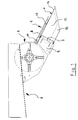
- FIG. 1 shows a side view of a distribution device 1 for a chopper 2, the rear 3 of a combine harvester, not shown is arranged.
- the distribution device 1 consists of a hood-like housing 4, which the chopper 2 is connected downstream.
- the housing 4 consists of two partial hoods 5 and 6, which are separately pivotably mounted on a base frame 7 and can be controlled independently of one another, shown in more detail in the figures 2, 3 and 4.
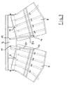
- On the base frame 7 are also the adjustment devices 8.1 and 8.2 for independent control of the partial hoods 5 and 6 stored. This becomes clearer in the illustration of FIG. 2, where in the top view the base frame 7 can be seen on which the partial hoods 5 and 6 are pivotally mounted on bearing pins 9 and 10.
- the adjustment devices are also on the base frame 7 8.1 and 8.2 stored at points 11 and 12 and stand via further storage points 13 and 14 with the partial hoods 5 and 6 in Connection.
- the adjusting device 8.1 as a hydraulic adjusting device 8.1 formed
- the adjusting device 8.2 as a hand-operated one is trained.
- FIGS. 02, 03 and 04 in FIGS Part hoods 5 and 6 in the middle area of the straw ejection straight guide plates 15.1, 15.2 and 15.3 arranged, being on the outer edge region a curved baffle 16 is provided.
- the partial hood 5 and 6 essentially from a cover plate 17 on which the Baffles 15.1, 15.2 and 15.3 and 16 are attached. Limited on the side is the cover plate 17 to protect the chopper from reaching into through a boundary plate 18, which under one to the outside pointing slope 19 extends to an opening to the outside To allow ejection.
- FIG. 02 shows the converging position of the partial hoods 5 and 6 and the figure 03 the divergent position, so that there is a close or a wide straw ejection results.
- FIG. 04 which is preferably operated by motor, especially near the coast is used to control against cross winds.
Landscapes
- Life Sciences & Earth Sciences (AREA)
- Environmental Sciences (AREA)
- Harvester Elements (AREA)
- Outside Dividers And Delivering Mechanisms For Harvesters (AREA)
Abstract
Description
- Figur 01:
- Den Heckbereich eines Mähdreschers in Seitenansicht
- Figur 02:
- Eine Draufsicht auf die Verteileinrichtung in konvergierender Stellung
- Figur 03:
- Eine weitere Draufsicht gemäß der Fig. 02 in divergierender Stellung
- Figur 04:
- Eine weitere Darstellung der Verteileinrichtung in Draufsicht in Ausrichtung zu einer Seite
Claims (5)
- Verteileinrichtung für Häcksler an einem Mähdrescher, welche aus einem haubenartig ausgebildeten Gehäuse besteht, in dem schwenkbar gelagerte Leitbleche in Gruppen angeordnet sind, um einen konvergierenden bzw. divergierenden Strohauswurf zu bewirken, dadurch gekennzeichnet, dass das Gehäuse (4) aus zwei Teilhauben (5) und (6) besteht, die getrennt an einem Grundrahmen (7) schwenkbar gelagert und unabhängig voneinander einstellbar sind.
- Verteileinrichtung nach Anspruch 1, dadurch gekennzeichnet, dass an dem Grundrahmen (7) ebenfalls die Verstelleinrichtungen (8.1) und (8.2) zur unabhängigen Ansteuerung der Teilhauben (5) und (6) gelagert sind.
- Verteileinrichtung nach den Ansprüchen 1 oder 2, dadurch gekennzeichnet, dass eine der Teilhauben (5) oder (6) ansteuerbar ist, während die andere in einem festen oder einstellbaren Abstand mit dieser verbunden ist.
- Verteileinrichtung nach einem oder mehreren der Ansprüche 1 bis 3, dadurch gekennzeichnet, dass die Teilhaube (5) bzw. (6) im wesentlichen aus einem Deckblech (17) besteht, an dem die Leitbleche (15.1, 15.2, 15.3, 16) befestigt sind, und seitlich ein Begrenzungsblech (18) angeordnet ist, welches unter einer Schräge (19) verläuft.
- Verteileinrichtung nach einem oder mehreren der vorhergehenden Ansprüche 1 bis 4, dadurch gekennzeichnet, dass die Verstelleinrichtungen (8.1) und (8.2) hand- und oder kraftbetrieben ausgebildet sind.
Applications Claiming Priority (2)
| Application Number | Priority Date | Filing Date | Title |
|---|---|---|---|
| DE20019686U | 2000-11-20 | ||
| DE20019686U DE20019686U1 (de) | 2000-11-20 | 2000-11-20 | Verteileinrichtung für Häcksler |
Publications (2)
| Publication Number | Publication Date |
|---|---|
| EP1208737A1 true EP1208737A1 (de) | 2002-05-29 |
| EP1208737B1 EP1208737B1 (de) | 2004-03-17 |
Family
ID=7949054
Family Applications (1)
| Application Number | Title | Priority Date | Filing Date |
|---|---|---|---|
| EP01127112A Expired - Lifetime EP1208737B1 (de) | 2000-11-20 | 2001-11-15 | Verteileinrichtung für Häcksler |
Country Status (2)
| Country | Link |
|---|---|
| EP (1) | EP1208737B1 (de) |
| DE (2) | DE20019686U1 (de) |
Cited By (5)
| Publication number | Priority date | Publication date | Assignee | Title |
|---|---|---|---|---|
| EP1374663A1 (de) * | 2002-06-19 | 2004-01-02 | CNH Belgium N.V. | Häcksler für ein landwirtschaftliches Gerät |
| DE202014102621U1 (de) | 2014-06-05 | 2015-06-11 | Heuling Maschinenbau Gmbh & Co. Kg | Verteileinrichtung für Häcksler an einem Mähdrescher |
| CN105706640A (zh) * | 2016-04-13 | 2016-06-29 | 河北宗申戈梅利农业机械制造有限公司 | 一种秸秆抛撒器 |
| WO2021099633A1 (en) * | 2019-11-22 | 2021-05-27 | Agco International Gmbh | Residue spreader for a combine harvester |
| US20240147913A1 (en) * | 2021-03-16 | 2024-05-09 | Wantech Pty Ltd. | Straw Processing System |
Families Citing this family (2)
| Publication number | Priority date | Publication date | Assignee | Title |
|---|---|---|---|---|
| CA2465142C (en) * | 2004-04-23 | 2009-06-02 | Redekop Chaff Systems Ltd. | Combine harvester with a spreader having independent spread width control |
| DE102006016674A1 (de) * | 2006-04-08 | 2007-10-18 | Deere & Company, Moline | Leitblech für eine Verteilvorrichtung eines Strohhäckslers |
Citations (6)
| Publication number | Priority date | Publication date | Assignee | Title |
|---|---|---|---|---|
| GB2165732A (en) * | 1984-10-20 | 1986-04-23 | Claas Ohg | Combine harvester with supplementary straw chopper |
| EP0212270A1 (de) * | 1985-08-23 | 1987-03-04 | BISO Bitter GmbH. & Co.KG. | Verteilereinrichtung für Häcksler |
| DE4313841A1 (de) * | 1993-04-27 | 1994-11-03 | Biso Maschf Gmbh | Mähdrescher |
| US5569081A (en) * | 1994-06-03 | 1996-10-29 | Claas Ohg Bwaxhaenkt Haftende Offene Handelsgesellschaft | Distributing device for chopper |
| EP0917819A1 (de) * | 1997-11-20 | 1999-05-26 | CLAAS Selbstfahrende Erntemaschinen GmbH | Anbauhäcksler eines Mähdreschers |
| EP0993764A1 (de) * | 1998-10-16 | 2000-04-19 | Rekordverken Sweden Ab | Anordnung einer Verteileinrichtung |
-
2000
- 2000-11-20 DE DE20019686U patent/DE20019686U1/de not_active Expired - Lifetime
-
2001
- 2001-11-15 DE DE50101695T patent/DE50101695D1/de not_active Expired - Fee Related
- 2001-11-15 EP EP01127112A patent/EP1208737B1/de not_active Expired - Lifetime
Patent Citations (6)
| Publication number | Priority date | Publication date | Assignee | Title |
|---|---|---|---|---|
| GB2165732A (en) * | 1984-10-20 | 1986-04-23 | Claas Ohg | Combine harvester with supplementary straw chopper |
| EP0212270A1 (de) * | 1985-08-23 | 1987-03-04 | BISO Bitter GmbH. & Co.KG. | Verteilereinrichtung für Häcksler |
| DE4313841A1 (de) * | 1993-04-27 | 1994-11-03 | Biso Maschf Gmbh | Mähdrescher |
| US5569081A (en) * | 1994-06-03 | 1996-10-29 | Claas Ohg Bwaxhaenkt Haftende Offene Handelsgesellschaft | Distributing device for chopper |
| EP0917819A1 (de) * | 1997-11-20 | 1999-05-26 | CLAAS Selbstfahrende Erntemaschinen GmbH | Anbauhäcksler eines Mähdreschers |
| EP0993764A1 (de) * | 1998-10-16 | 2000-04-19 | Rekordverken Sweden Ab | Anordnung einer Verteileinrichtung |
Cited By (6)
| Publication number | Priority date | Publication date | Assignee | Title |
|---|---|---|---|---|
| EP1374663A1 (de) * | 2002-06-19 | 2004-01-02 | CNH Belgium N.V. | Häcksler für ein landwirtschaftliches Gerät |
| DE202014102621U1 (de) | 2014-06-05 | 2015-06-11 | Heuling Maschinenbau Gmbh & Co. Kg | Verteileinrichtung für Häcksler an einem Mähdrescher |
| CN105706640A (zh) * | 2016-04-13 | 2016-06-29 | 河北宗申戈梅利农业机械制造有限公司 | 一种秸秆抛撒器 |
| WO2021099633A1 (en) * | 2019-11-22 | 2021-05-27 | Agco International Gmbh | Residue spreader for a combine harvester |
| US11712002B2 (en) | 2019-11-22 | 2023-08-01 | Agco International Gmbh | Residue spreader for a combine harvester |
| US20240147913A1 (en) * | 2021-03-16 | 2024-05-09 | Wantech Pty Ltd. | Straw Processing System |
Also Published As
| Publication number | Publication date |
|---|---|
| DE20019686U1 (de) | 2002-01-10 |
| DE50101695D1 (de) | 2004-04-22 |
| EP1208737B1 (de) | 2004-03-17 |
Similar Documents
| Publication | Publication Date | Title |
|---|---|---|
| DE3530195C1 (de) | Verteilereinrichtung fuer Haecksler | |
| EP1408733B1 (de) | Einrichtung zur verstellung der sieböffnungsweite an mähdreschern | |
| EP2462795B1 (de) | Pneumatische Verteilmaschine | |
| EP0316923B1 (de) | Verteilereinrichtung für Häcksler | |
| DE202008008487U1 (de) | Pneumatisch arbeitende Verteilmaschine für granulatförmiges Verteilgut | |
| DE69736569T2 (de) | Landwirtschaftliche Feldspritze | |
| EP1208737B1 (de) | Verteileinrichtung für Häcksler | |
| DE2815936C2 (de) | ||
| DE19626937C2 (de) | Vorrichtung zur Geräuschminderung an einer Schiebedachöffnung eines Fahrzeugs | |
| DE2636488C2 (de) | ||
| EP0043089B1 (de) | Farbkasten zur Aufnahme von Offset-Druckfarbe | |
| DE112004001079T5 (de) | Mähdrescher mit einem Verteiler für Pflanzenreste | |
| DE1231050B (de) | Spruehgeraet zur Bekaempfung von Pflanzenschaedlingen | |
| EP1224859A1 (de) | Mit Schneidmessern besetzte Schnecke eines Futtermischers | |
| DE3838936C2 (de) | ||
| DE10354671A1 (de) | Weiche für in mehrere Teil-Bahnen aufzuteilende Bahn | |
| DE3119954C2 (de) | Mähdrescher | |
| DE69713966T2 (de) | Mäher mit Stütz- und Transporträdern | |
| DE823816C (de) | Ein- oder mehrschariger Beetpflug zum Anbauen an eine Zugmaschine | |
| DE3618680C2 (de) | Verstellbares Pflegebett | |
| DE10232917A1 (de) | Fahrzeugdach | |
| DE2915245C2 (de) | Mähbalken | |
| DE10140458A1 (de) | Schneidmesser für Mischschnecken | |
| DE2532785A1 (de) | Vorrichtung zum entnehmen von silage | |
| DE3211137A1 (de) | Zerkleinerungseinrichtung |
Legal Events
| Date | Code | Title | Description |
|---|---|---|---|
| PUAI | Public reference made under article 153(3) epc to a published international application that has entered the european phase |
Free format text: ORIGINAL CODE: 0009012 |
|
| AK | Designated contracting states |
Kind code of ref document: A1 Designated state(s): AT BE CH CY DE DK ES FI FR GB GR IE IT LI LU MC NL PT SE TR |
|
| AX | Request for extension of the european patent |
Free format text: AL;LT;LV;MK;RO;SI |
|
| 17P | Request for examination filed |
Effective date: 20020706 |
|
| AKX | Designation fees paid |
Designated state(s): BE DE DK FR IT SE |
|
| GRAP | Despatch of communication of intention to grant a patent |
Free format text: ORIGINAL CODE: EPIDOSNIGR1 |
|
| GRAS | Grant fee paid |
Free format text: ORIGINAL CODE: EPIDOSNIGR3 |
|
| GRAA | (expected) grant |
Free format text: ORIGINAL CODE: 0009210 |
|
| AK | Designated contracting states |
Kind code of ref document: B1 Designated state(s): BE DE DK FR IT SE |
|
| REG | Reference to a national code |
Ref country code: IE Ref legal event code: FG4D Free format text: GERMAN |
|
| REF | Corresponds to: |
Ref document number: 50101695 Country of ref document: DE Date of ref document: 20040422 Kind code of ref document: P |
|
| PG25 | Lapsed in a contracting state [announced via postgrant information from national office to epo] |
Ref country code: DK Free format text: LAPSE BECAUSE OF FAILURE TO SUBMIT A TRANSLATION OF THE DESCRIPTION OR TO PAY THE FEE WITHIN THE PRESCRIBED TIME-LIMIT Effective date: 20040617 |
|
| REG | Reference to a national code |
Ref country code: SE Ref legal event code: TRGR |
|
| REG | Reference to a national code |
Ref country code: IE Ref legal event code: FD4D |
|
| ET | Fr: translation filed | ||
| PLBE | No opposition filed within time limit |
Free format text: ORIGINAL CODE: 0009261 |
|
| STAA | Information on the status of an ep patent application or granted ep patent |
Free format text: STATUS: NO OPPOSITION FILED WITHIN TIME LIMIT |
|
| 26N | No opposition filed |
Effective date: 20041220 |
|
| PGFP | Annual fee paid to national office [announced via postgrant information from national office to epo] |
Ref country code: DE Payment date: 20060831 Year of fee payment: 6 |
|
| PGFP | Annual fee paid to national office [announced via postgrant information from national office to epo] |
Ref country code: BE Payment date: 20061010 Year of fee payment: 6 |
|
| PGFP | Annual fee paid to national office [announced via postgrant information from national office to epo] |
Ref country code: IT Payment date: 20061130 Year of fee payment: 6 |
|
| PGFP | Annual fee paid to national office [announced via postgrant information from national office to epo] |
Ref country code: SE Payment date: 20060920 Year of fee payment: 6 |
|
| BERE | Be: lapsed |
Owner name: *HEULING MASCHINENBAU G.M.B.H. & CO. K.G. Effective date: 20071130 |
|
| EUG | Se: european patent has lapsed | ||
| PG25 | Lapsed in a contracting state [announced via postgrant information from national office to epo] |
Ref country code: BE Free format text: LAPSE BECAUSE OF NON-PAYMENT OF DUE FEES Effective date: 20071130 |
|
| PG25 | Lapsed in a contracting state [announced via postgrant information from national office to epo] |
Ref country code: SE Free format text: LAPSE BECAUSE OF NON-PAYMENT OF DUE FEES Effective date: 20071116 Ref country code: DE Free format text: LAPSE BECAUSE OF NON-PAYMENT OF DUE FEES Effective date: 20080603 |
|
| PGFP | Annual fee paid to national office [announced via postgrant information from national office to epo] |
Ref country code: FR Payment date: 20060928 Year of fee payment: 6 |
|
| REG | Reference to a national code |
Ref country code: FR Ref legal event code: ST Effective date: 20080930 |
|
| PG25 | Lapsed in a contracting state [announced via postgrant information from national office to epo] |
Ref country code: FR Free format text: LAPSE BECAUSE OF NON-PAYMENT OF DUE FEES Effective date: 20071130 |
|
| PG25 | Lapsed in a contracting state [announced via postgrant information from national office to epo] |
Ref country code: IT Free format text: LAPSE BECAUSE OF NON-PAYMENT OF DUE FEES Effective date: 20071115 |