EP1207336A1 - Stativ mit Parallelogrammträger und Balanciermechanismus - Google Patents
Stativ mit Parallelogrammträger und Balanciermechanismus Download PDFInfo
- Publication number
- EP1207336A1 EP1207336A1 EP01125608A EP01125608A EP1207336A1 EP 1207336 A1 EP1207336 A1 EP 1207336A1 EP 01125608 A EP01125608 A EP 01125608A EP 01125608 A EP01125608 A EP 01125608A EP 1207336 A1 EP1207336 A1 EP 1207336A1
- Authority
- EP
- European Patent Office
- Prior art keywords
- sensor
- support arm
- arm
- stand according
- support arms
- Prior art date
- Legal status (The legal status is an assumption and is not a legal conclusion. Google has not performed a legal analysis and makes no representation as to the accuracy of the status listed.)
- Granted
Links
- 239000000969 carrier Substances 0.000 description 5
- 238000005452 bending Methods 0.000 description 3
- 230000015572 biosynthetic process Effects 0.000 description 3
- 238000010276 construction Methods 0.000 description 3
- 238000005259 measurement Methods 0.000 description 3
- 230000004913 activation Effects 0.000 description 1
- 239000003795 chemical substances by application Substances 0.000 description 1
- 230000007423 decrease Effects 0.000 description 1
- 230000000694 effects Effects 0.000 description 1
- 239000000463 material Substances 0.000 description 1
- 230000007246 mechanism Effects 0.000 description 1
- 238000000034 method Methods 0.000 description 1
- 230000003287 optical effect Effects 0.000 description 1
- 238000005303 weighing Methods 0.000 description 1
Images



Classifications
-
- F—MECHANICAL ENGINEERING; LIGHTING; HEATING; WEAPONS; BLASTING
- F16—ENGINEERING ELEMENTS AND UNITS; GENERAL MEASURES FOR PRODUCING AND MAINTAINING EFFECTIVE FUNCTIONING OF MACHINES OR INSTALLATIONS; THERMAL INSULATION IN GENERAL
- F16M—FRAMES, CASINGS OR BEDS OF ENGINES, MACHINES OR APPARATUS, NOT SPECIFIC TO ENGINES, MACHINES OR APPARATUS PROVIDED FOR ELSEWHERE; STANDS; SUPPORTS
- F16M11/00—Stands or trestles as supports for apparatus or articles placed thereon ; Stands for scientific apparatus such as gravitational force meters
- F16M11/20—Undercarriages with or without wheels
- F16M11/2007—Undercarriages with or without wheels comprising means allowing pivoting adjustment
- F16M11/2021—Undercarriages with or without wheels comprising means allowing pivoting adjustment around a horizontal axis
-
- F—MECHANICAL ENGINEERING; LIGHTING; HEATING; WEAPONS; BLASTING
- F16—ENGINEERING ELEMENTS AND UNITS; GENERAL MEASURES FOR PRODUCING AND MAINTAINING EFFECTIVE FUNCTIONING OF MACHINES OR INSTALLATIONS; THERMAL INSULATION IN GENERAL
- F16M—FRAMES, CASINGS OR BEDS OF ENGINES, MACHINES OR APPARATUS, NOT SPECIFIC TO ENGINES, MACHINES OR APPARATUS PROVIDED FOR ELSEWHERE; STANDS; SUPPORTS
- F16M11/00—Stands or trestles as supports for apparatus or articles placed thereon ; Stands for scientific apparatus such as gravitational force meters
- F16M11/20—Undercarriages with or without wheels
- F16M11/2092—Undercarriages with or without wheels comprising means allowing depth adjustment, i.e. forward-backward translation of the head relatively to the undercarriage
-
- F—MECHANICAL ENGINEERING; LIGHTING; HEATING; WEAPONS; BLASTING
- F16—ENGINEERING ELEMENTS AND UNITS; GENERAL MEASURES FOR PRODUCING AND MAINTAINING EFFECTIVE FUNCTIONING OF MACHINES OR INSTALLATIONS; THERMAL INSULATION IN GENERAL
- F16M—FRAMES, CASINGS OR BEDS OF ENGINES, MACHINES OR APPARATUS, NOT SPECIFIC TO ENGINES, MACHINES OR APPARATUS PROVIDED FOR ELSEWHERE; STANDS; SUPPORTS
- F16M11/00—Stands or trestles as supports for apparatus or articles placed thereon ; Stands for scientific apparatus such as gravitational force meters
- F16M11/20—Undercarriages with or without wheels
- F16M11/24—Undercarriages with or without wheels changeable in height or length of legs, also for transport only, e.g. by means of tubes screwed into each other
-
- G—PHYSICS
- G02—OPTICS
- G02B—OPTICAL ELEMENTS, SYSTEMS OR APPARATUS
- G02B7/00—Mountings, adjusting means, or light-tight connections, for optical elements
- G02B7/001—Counterbalanced structures, e.g. surgical microscopes
-
- F—MECHANICAL ENGINEERING; LIGHTING; HEATING; WEAPONS; BLASTING
- F16—ENGINEERING ELEMENTS AND UNITS; GENERAL MEASURES FOR PRODUCING AND MAINTAINING EFFECTIVE FUNCTIONING OF MACHINES OR INSTALLATIONS; THERMAL INSULATION IN GENERAL
- F16M—FRAMES, CASINGS OR BEDS OF ENGINES, MACHINES OR APPARATUS, NOT SPECIFIC TO ENGINES, MACHINES OR APPARATUS PROVIDED FOR ELSEWHERE; STANDS; SUPPORTS
- F16M2200/00—Details of stands or supports
- F16M2200/04—Balancing means
- F16M2200/044—Balancing means for balancing rotational movement of the undercarriage
-
- F—MECHANICAL ENGINEERING; LIGHTING; HEATING; WEAPONS; BLASTING
- F16—ENGINEERING ELEMENTS AND UNITS; GENERAL MEASURES FOR PRODUCING AND MAINTAINING EFFECTIVE FUNCTIONING OF MACHINES OR INSTALLATIONS; THERMAL INSULATION IN GENERAL
- F16M—FRAMES, CASINGS OR BEDS OF ENGINES, MACHINES OR APPARATUS, NOT SPECIFIC TO ENGINES, MACHINES OR APPARATUS PROVIDED FOR ELSEWHERE; STANDS; SUPPORTS
- F16M2200/00—Details of stands or supports
- F16M2200/06—Arms
- F16M2200/063—Parallelogram arms
Definitions
- the invention relates to a tripod that can be balanced according to the preamble of claim 1.
- Tripods with electronic balancing mechanisms have measuring units, that measure an imbalance.
- Such measuring units are, for example in US patent US 5528417, in DE 4320443 A1 and DE 4334069 A1 and in published in WO 97/13997 by the applicant.
- the well-known measuring units often measure bending forces or paths resulting from bending with the brakes on Tripod. If necessary, use angle sensors, optical Position sensors or bending sensors.
- Under the braked tripod is a To understand tripod, of which at least one support arm by means of a brake the stand is kept pivot-free. In practice, such Brakes usually between points fixed to the stand and parallelogram carriers or arranged between adjacent arms of a parallelogram carrier.
- the invention has for its object a new generation of measuring units to create that with particularly inexpensive, existing sensors realized and easily assembled and / or integrated into tripod components can be.
- a pressure, Shear force or kink sensor arranged between one with the load connected part of the support arm and a braked part of the tripod Measures forces and the measured values for balancing control are available provides.
- one of the carriers of the parallelogram is alternatively directly a sensor installed, the buckling or occurring there Measures shear forces.
- a sensor By integrating a sensor into a weakened one or interrupted position of a support arm of a parallelogram carrier on the one hand found a good integrative solution that saves space.
- the measurement is moved to a location that is included with each tripod Parallelogram carriers are present.
- the measuring unit itself as Standard product can be produced, which with any parallelogram can be used.
- the invention is not based on the use of a shear force sensor in one Parallelogram carrier restricted, but rather also includes the Use of a shear force carrier for unbalance measurement in a tripod generally. This is because the knowledge of the application of a Shear force sensor for balance measurements also with other tripod constructions, that do without a parallelogram carrier can be advantageous, especially since they to a significant cost reduction and space saving in the measuring device leads.
- the state in which the unbalance forces in a support arm of a parallelogram carrier can be best measured is the one where at least one joint of the parallelogram carrier is braked, or at which the above-mentioned support is braked, but the bracket itself can drift slightly. Especially if the as Kink sensor working sensor located near the brake can in the braked state, the imbalances with good measuring accuracy be measured.
- the call of the Sensor data controlled by a computer the Sensor output data supplied to an automatic balancing device become.
- a hanging on a cable Mass is provided as a counterweight and the cable on an electric motor sliding shoe is attached to a balance arm.
- the senor is encompassing Assigned elements that perform a support function in the event of an overload.
- the invention can be advantageous with a new tripod according to the Utility model applications filed on the same day as DE 200 19 105, DE 200 19 109 and DE 200 19 107 of the applicant are used.
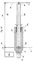
- the load G - in the preferred application an operating microscope - depends by means of a swivel bracket (not shown) (for example a swivel bracket gem. the applicant's international patent application WO 97/47240 on a tripod.
- the swivel bracket and thus the load G reach out to the extreme lower joint 58 of a parallelogram carrier designated overall by 2b on.
- the upper bracket 59 is conventionally formed while the lower support arm 60 has a novel design. In the area of his tripod-side linkage 61 to a base 12, it is weakened in material, or interrupted training.
- a base part 62 is on the base via a brake (brakeable clutch) 63 12 hinged.
- the base part 62 can be pivoted up and down by the activation of the brake 63 can be prevented.
- the base part 62 is one Measuring unit 64 designed as a platform load cell rigidly connected to the the other end rigidly receives the support arm part 65 of the support arm 60.
- the connection between the base part 62 and the support arm part 65 via the Measuring unit 64 is so stable that with brake 63 released, the lower support arm. 60 can pivot up and down parallel to the upper support arm 59.
- the lower support arm 60 In the balanced state, which is achieved when, for example, a symbolically indicated balance weight AGa, however, the same number opposite torque generated by the load G is generated the lower support arm 60 is only loaded under pressure.
- the only one on the bottom Support arm 60 effective force component thus extends from the joint 58 to the linkage 61 along its longitudinal axis 66.
- the sensor 64 is insensitive to tensile and compressive loads, i.e. it will be due no imbalance values were measured for these forces.
- transverse forces in the context of this invention arise from forces or moments that obliquely or perpendicular to the longitudinal extent of the - in the present example - Lower arm 60 act.
- the base part 62 is possibly above the basic need for its function also equipped with other features that further develop the Represent invention: protrude an upper support arm 67 and a lower support arm 68 the sensor 64 and extend to the support arm part 65. Opposite this they have a game labeled "x". This game gives the sensor 64 enough space to provide its sensor performance. However, it is so small that in the event of a particularly high load or overload, a contact between the support parts 67 or 68 and the support arm part 65 occurs, this support each other and thereby prevent damage to the sensor 64.
- FIG. 2 shows the perspective view of an insert used according to the invention Sensor 64 can be seen. It has measuring zones 69 and / or 70, a sealed electronic circuit 71 and connection cable 72.
- the sensor is, for example, a PW4F-2 platform load cell from the company HBM Spectris Group / Darmstadt (DE).
- Threaded bores 73 and 74 are provided at both ends of the sensor 64, to the one hand with the base part 62 and on the other hand with the support arm part 65 to be screwed.
- the centrally arranged double elongated hole 75 can vary in shape from sensor to sensor however in the form shown for the present application standard training.
- FIG. 2a shows schematically the clamping or application of a buckling or Shear force sensor 64 selected platform load cell.
- FIG.3 When assembling acc. Fig.3 is the boom of a tripod in its horizontal Shown rest position.
- This is nested trained so that you can mainly see the upper bracket 59, the is U-shaped in cross-section and the inside upwards cranked part of the lower support arm 60 receives.
- the lower arm 60 is, as shown schematically in Figure 1, divided into two and includes the support arm part 65 and the base part 62, in which the sensor 64 is integrated according to FIG. 6 is.
- a swivel bracket 79 is mounted, which the load G, or an operating microscope.
- the upper support arm 59 is extended beyond its pivot point 76 and there forms the compensating arm 22.
- a sliding shoe 23 is displaceable there stored on which a cable 24 is attached.
- a balance weight AGa depends.
- the Sliding shoe 23 is preferably electronically or electrically controlled, depending on the determined buckling or shear forces on Sensor 64 in the base part 62.
- the compensation range is preferred; i.e. the Area formed to the left of the articulation points 61 and 76 as in the patent application DE 200 19 105 and DE 200 19 109 specified. More preferred is, in the case of using a cable 24, as in the embodiment gem. Fig.3 indicated the use of a rope safety device accordingly the application DE 200 19 107.
- the detailed design of the swivel bracket 79 is not in the present because they are responsible for the formation and attachment of the sensor 64 or for the formation of the parallelogram carrier 2b without significant importance is.
- the formation of the lower support arm 60 shown in FIGS. 4-6 shows an optimally integrated base part 62 and a simple, slat-shaped Support arm part 65, the optimally recessed from the U-shaped upper support arm 59 is added.
- the support arm part 65 can also consist of parallel part carriers or shaped pipes exist.
- the sensor 64 is protected by a cover 81 in the base part 62.
- the structures acc. 7 and 8 represent variants of the invention in which instead of a platform weighing sensor, conventional buckling sensors 64a and 64b can be used. These sensors are in places where the lower arm 60a or 60b is weakened. The in these places buckling values measured by sensors 64a or 64b correspond to the Shear force values, which are measured and permitted with the sensor 64 thus also a conclusion on the imbalance.
- the lower Carrier is designed as a continuous support arm 60c. It extends from the joint 58 to the tripod-side linkage 61, where not only the support arm 60c, but also the essentially fork-shaped base part 62a can be pivoted are stored.
- the mobility of the base part 62a can be controlled by a brake 63 are braked.
- the mobility of the support arm 60c at the pivot point 61 is limited to the game x.
- Pressure sensors 64c are attached to the support arms 67 and 68 shown balanced state (and with the brake 63 applied) the support arm 60c have the play labeled "x". With imbalance a torque occurs around the joint 76, which leads to the fact that the support arm 78 drifts up or down. The support arm 78 transmits this drift to the support arm 60c, so that the play x increases when tightened Brake 63 on lower pressure sensor 64c grows or decreases while at the upper pressure sensor 64c, the play x is changed in opposite directions. As soon as one of the two sensors 64c is touched, thus a pressure force occurs measured and passed on as an imbalance value.
- Fig. 11 shows a variant of the structure shown in Fig. 10, in which a shear force sensor 64a is used instead of the pressure sensors 64c. This is on the one hand with the individual support arm of the base part 62a and on the other hand firmly connected to the support arm 60c and is capable of being tightened Brake 63 record and detect the shear forces that occur.
- the game x is omitted here. This could be can also be omitted in the construction according to FIG. 10, but this is too expensive Adjustment processes should lead to the two pressure sensors 64c.
- the upper and lower support arms 67a and 68a are analogous to the structure according to FIG provided, in this embodiment the lower support arm 68a tab-shaped protrudes from the base part 62a.
- these parts can also be parallel be arranged to each other and the like by bolts. be connected, whereby the support surfaces between the bolts or the like. and elongated holes, larger holes or the like. be formed.
Landscapes
- Engineering & Computer Science (AREA)
- General Engineering & Computer Science (AREA)
- Mechanical Engineering (AREA)
- Physics & Mathematics (AREA)
- General Physics & Mathematics (AREA)
- Optics & Photonics (AREA)
- Force Measurement Appropriate To Specific Purposes (AREA)
- Measurement Of Force In General (AREA)
Abstract
Description
- 2b -
- Parallelogrammträger
- 12 -
- Basis bzw. Grundkörper
- 20 -
- Stativfuss
- 21 -
- Ständersäule
- 22, 22a -
- Ausgleichsarm
- 23 -
- Gleitschuh
- 24 -
- Seilzug
- 58 -
- Gelenk
- 59 -
- Oberer Tragarm
- 60 -
- Unterer Tragarm
- 60a, b, c -
- Varianten des unteren Tragarms
- 61 -
- Stativseitige Anlenkung (Schwenkachse)
- 62,a -
- Basisteil bzw. Messarm
- 63 -
- Bremse (Einbremsbare Kupplung)
- 64 -
- Messeinheit bzw. Sensor bzw. Plattform-Wägezelle
- 64a, b -
- Scherkraftsensor
- 64c
- - Drucksensor
- 65 -
- Tragarmteil
- 66 -
- Achse
- 67 -
- Oberer Stützarm
- 68 -
- Unterer Stützarm
- 69, 70 -
- Messzonen
- 71 -
- elektronische Schaltung
- 72 -
- Anschlusskabel
- 73 -
- Gewindebohrung
- 74 -
- Gewindebohrungen
- 75 -
- Doppellanglochausnehmung
- 76 -
- Anlenkpunkt
- 77 -
- Armteilstück
- 78 -
- Senkrechter Tragarm
- 79 -
- Schwenkträger
- 80 -
- Verstellmechanismus
- 81 -
- Abdeckung
- 182a,b -
- unterbrochene Stelle im Tragarm 60
- AG,a -
- Ausgleichsgewicht
- G -
- Last bzw. Gewicht des Mikroskops
Claims (10)
- Ausbalancierbares Stativ mit einem die Last (G) aufnehmenden Parallelogrammträger (2b) aus wenigstens drei Tragarmen (59, 60, 78), von denen zwei parallele Tragarme (59, 60) gegenüber einer Basis (12) abgestützt sind, mit einer Messeinheit im Bereich von einem der Tragarme (60), dadurch gekennzeichnet, dass die Messeinheit als Sensor (64) ausgebildet ist und zwischen einem der beiden horizontalen Tragarme (60) und einem eingebremsten Basisteil (62) des Stativs Kräfte misst und im Betriebszustand die Messwerte für die Balanciersteuerung zur Verfügung hält.
- Stativ nach Anspruch 1, dadurch gekennzeichnet, dass der Sensor (64) zwischen einem der horizontalen Tragarme (60) und einem mittels Bremse (63) festlegbaren Basisteil (62) angeordnet ist.
- Stativ nach Anspruch 2, dadurch gekennzeichnet, dass der Basisteil (62) parallel zum horizontalen Tragarm (60) angeordnet und als Messarm ausgebildet ist, wobei der Messarm mit dem horizontalen Tragarm (60) um dieselbe Achse (61) schwenkbar und gegenüber der Basis (12) einbremsbar ausgebildet ist.
- Stativ nach Anspruch 2 oder 3, dadurch gekennzeichnet, dass der Basisteil (62) wenigstens teilweise in Serie zum horizontalen Tragarm (60) bzw. zu einem Tragarmteil (65) angeordnet ist und der Sensor (64) als serielles Zwischenglied zwischen dem Basisteil (62) und dem horizontalen Tragarm (60) bzw. Tragarmteil (65) montiert ist.
- Stativ nach einem der vorhergehenden Ansprüche, dadurch gekenn- zeichnet, dass einer der beiden Tragarme (60) eine im Querschnitt verjüngte oder unterbrochene Stelle (182) aufweist, an der die Messeinheit zur Detektion von Querbelastungen an dieser Stelle vorgesehen ist.
- Stativ nach einem der vorhergehenden Ansprüche, dadurch gekennzeichnet, dass wenigstens einer der parallelen Tragarme (60) an seiner Anlenkstelle (61) bremsbar ist.
- Stativ nach einem der vorhergehenden Ansprüche, dadurch gekennzeichnet, dass der Sensor (64) als Scherkraft-, Knick- oder Druckkraftsensor ausgebildet ist.
- Stativ nach einem der vorhergehenden Ansprüche, dadurch gekennzeichnet, dass der Sensor (64) unmittelbar an oder in einem der parallelen Tragarme (60) oder an einer geschwächten oder unterbrochenen Stelle des Tragarms (60a, 60b) befestigt ist.
- Stativ nach einem der vorhergehenden Ansprüche, dadurch gekennzeichnet, dass der Sensor (64) bei einem der beiden horizontalen Tragarme (60) zwei Teile eines verjüngten Tragarms (60a) oder eines geschwächten Tragarms (60b) überbrückt, wobei der der Basis (12) zugewandte Bereich der beiden Teile die Funktion des Messarms übernimmt.
- Stativ nach einem der vorhergehenden Ansprüche, dadurch gekennzeichnet, dass der Sensor (64) als Scherkraftsensor ausgebildet ist, der Scherkräfte zwischen zwei benachbarten Teilen (62,65) eines Tragarms (60) misst.
Applications Claiming Priority (2)
| Application Number | Priority Date | Filing Date | Title |
|---|---|---|---|
| DE20019106U DE20019106U1 (de) | 2000-11-12 | 2000-11-12 | Stativ mit Parallelogrammträger und Balanciermechanismus |
| DE20019106U | 2000-11-12 |
Publications (2)
| Publication Number | Publication Date |
|---|---|
| EP1207336A1 true EP1207336A1 (de) | 2002-05-22 |
| EP1207336B1 EP1207336B1 (de) | 2006-12-20 |
Family
ID=7948653
Family Applications (1)
| Application Number | Title | Priority Date | Filing Date |
|---|---|---|---|
| EP01125608A Expired - Lifetime EP1207336B1 (de) | 2000-11-12 | 2001-10-26 | Stativ mit Parallelogrammträger und Balanciermechanismus |
Country Status (4)
| Country | Link |
|---|---|
| US (1) | US6637274B2 (de) |
| EP (1) | EP1207336B1 (de) |
| JP (1) | JP4185685B2 (de) |
| DE (2) | DE20019106U1 (de) |
Families Citing this family (10)
| Publication number | Priority date | Publication date | Assignee | Title |
|---|---|---|---|---|
| DE20019107U1 (de) | 2000-11-12 | 2001-01-25 | Leica Microsystems Ag, Heerbrugg | Stativ |
| DE20019105U1 (de) | 2000-11-12 | 2001-05-23 | Leica Microsystems Ag, Heerbrugg | Stativ |
| DE20019106U1 (de) * | 2000-11-12 | 2001-02-22 | Leica Microsystems Ag, Heerbrugg | Stativ mit Parallelogrammträger und Balanciermechanismus |
| US6539333B1 (en) | 2002-01-04 | 2003-03-25 | Leica Microsystems Ag | Stand having an automatic balancing device |
| US6935196B1 (en) * | 2003-11-14 | 2005-08-30 | David M. Tumlin | Method and apparatus for testing the structural integrity of offshore lifting containers |
| DE102004017970A1 (de) * | 2004-04-12 | 2005-10-27 | Leica Microsystems (Schweiz) Ag | Stativ, insbesondere für Operationsmikroskope, mit einem Kraftspeicherelement |
| DE102004017971A1 (de) * | 2004-04-12 | 2005-10-27 | Leica Microsystems (Schweiz) Ag | Stativ, insbesondere für Operationsmikroskope, mit einem Kraftspeicherelement |
| US7954554B2 (en) | 2006-03-10 | 2011-06-07 | Schlumberger Technology Corporation | Coiled tubing equipment lifting methods |
| CN104296901A (zh) * | 2014-11-04 | 2015-01-21 | 苏州精创光学仪器有限公司 | 焊接残余应力小孔测量方法 |
| EP3220038B1 (de) | 2016-03-17 | 2018-10-24 | Leica Instruments (Singapore) Pte. Ltd. | Verfahren zum ausgleichen einer last mittels eines tragsystem und tragsystem |
Citations (11)
| Publication number | Priority date | Publication date | Assignee | Title |
|---|---|---|---|---|
| JPH04142507A (ja) * | 1990-10-03 | 1992-05-15 | Topcon Corp | 顕微鏡装置 |
| DE4334068A1 (de) | 1992-10-08 | 1994-04-14 | Fuji Heavy Ind Ltd | Verfahren zum Detektieren von Motorfehlzündungen |
| DE4320443A1 (de) | 1993-06-21 | 1994-12-22 | Zeiss Carl Fa | Ausbalancierbares Stativ |
| DE4334069A1 (de) * | 1993-06-21 | 1995-04-13 | Zeiss Carl Fa | Ausbalancierbares Stativ |
| US5528417A (en) | 1992-12-28 | 1996-06-18 | Mitaka Kohki Co., Ltd. | Stand apparatus for medical optical equipment |
| WO1997013997A1 (de) | 1995-10-12 | 1997-04-17 | Leica Ag | Stativ |
| WO1997047240A1 (de) | 1996-06-10 | 1997-12-18 | Leica Ag | System zur positionserfassung mit einem marker und marker zur anwendung in einem solchen system |
| DE20019107U1 (de) | 2000-11-12 | 2001-01-25 | Leica Microsystems Ag, Heerbrugg | Stativ |
| DE20019106U1 (de) * | 2000-11-12 | 2001-02-22 | Leica Microsystems Ag, Heerbrugg | Stativ mit Parallelogrammträger und Balanciermechanismus |
| DE20019109U1 (de) | 2000-11-12 | 2001-02-22 | Leica Microsystems Ag, Heerbrugg | Stativ, insbesondere für Operationsmikroskope |
| DE20019105U1 (de) | 2000-11-12 | 2001-05-23 | Leica Microsystems Ag, Heerbrugg | Stativ |
Family Cites Families (7)
| Publication number | Priority date | Publication date | Assignee | Title |
|---|---|---|---|---|
| US4582152A (en) * | 1984-08-29 | 1986-04-15 | Armour Pharmaceutical Co. | Weighing mechanism |
| JPH0546439Y2 (de) * | 1989-06-22 | 1993-12-06 | ||
| JP2598615B2 (ja) * | 1994-08-09 | 1997-04-09 | 三鷹光器株式会社 | 医療用スタンド装置のたわみ補正構造 |
| US5721399A (en) * | 1996-06-07 | 1998-02-24 | Latiri; Mondher | Golf club swing weight scale |
| JP2993906B2 (ja) * | 1997-03-31 | 1999-12-27 | 三鷹光器株式会社 | 医療用スタンド装置 |
| US5844142A (en) * | 1997-04-30 | 1998-12-01 | Ethicon, Inc. | Pull test apparatus for permanently attached sutures |
| US6425865B1 (en) * | 1998-06-12 | 2002-07-30 | The University Of British Columbia | Robotically assisted medical ultrasound |
-
2000
- 2000-11-12 DE DE20019106U patent/DE20019106U1/de not_active Expired - Lifetime
-
2001
- 2001-10-26 EP EP01125608A patent/EP1207336B1/de not_active Expired - Lifetime
- 2001-10-26 DE DE50111676T patent/DE50111676D1/de not_active Expired - Lifetime
- 2001-11-08 US US10/008,285 patent/US6637274B2/en not_active Expired - Lifetime
- 2001-11-12 JP JP2001346367A patent/JP4185685B2/ja not_active Expired - Fee Related
Patent Citations (13)
| Publication number | Priority date | Publication date | Assignee | Title |
|---|---|---|---|---|
| JPH04142507A (ja) * | 1990-10-03 | 1992-05-15 | Topcon Corp | 顕微鏡装置 |
| DE4334068A1 (de) | 1992-10-08 | 1994-04-14 | Fuji Heavy Ind Ltd | Verfahren zum Detektieren von Motorfehlzündungen |
| US5528417A (en) | 1992-12-28 | 1996-06-18 | Mitaka Kohki Co., Ltd. | Stand apparatus for medical optical equipment |
| US5667186A (en) * | 1993-06-21 | 1997-09-16 | Carl-Zeiss-Stiftung | Stand for mounting various loads |
| DE4334069A1 (de) * | 1993-06-21 | 1995-04-13 | Zeiss Carl Fa | Ausbalancierbares Stativ |
| DE4320443A1 (de) | 1993-06-21 | 1994-12-22 | Zeiss Carl Fa | Ausbalancierbares Stativ |
| WO1997013997A1 (de) | 1995-10-12 | 1997-04-17 | Leica Ag | Stativ |
| US6129319A (en) * | 1995-10-12 | 2000-10-10 | Leica Microsystems Ag | Automatically adjustable counterbalanced stand |
| WO1997047240A1 (de) | 1996-06-10 | 1997-12-18 | Leica Ag | System zur positionserfassung mit einem marker und marker zur anwendung in einem solchen system |
| DE20019107U1 (de) | 2000-11-12 | 2001-01-25 | Leica Microsystems Ag, Heerbrugg | Stativ |
| DE20019106U1 (de) * | 2000-11-12 | 2001-02-22 | Leica Microsystems Ag, Heerbrugg | Stativ mit Parallelogrammträger und Balanciermechanismus |
| DE20019109U1 (de) | 2000-11-12 | 2001-02-22 | Leica Microsystems Ag, Heerbrugg | Stativ, insbesondere für Operationsmikroskope |
| DE20019105U1 (de) | 2000-11-12 | 2001-05-23 | Leica Microsystems Ag, Heerbrugg | Stativ |
Non-Patent Citations (1)
| Title |
|---|
| PATENT ABSTRACTS OF JAPAN vol. 016, no. 421 (P - 1414) 4 September 1992 (1992-09-04) * |
Also Published As
| Publication number | Publication date |
|---|---|
| EP1207336B1 (de) | 2006-12-20 |
| JP2002221455A (ja) | 2002-08-09 |
| DE50111676D1 (de) | 2007-02-01 |
| JP4185685B2 (ja) | 2008-11-26 |
| US6637274B2 (en) | 2003-10-28 |
| DE20019106U1 (de) | 2001-02-22 |
| US20020144558A1 (en) | 2002-10-10 |
Similar Documents
| Publication | Publication Date | Title |
|---|---|---|
| DE2556428C3 (de) | Wägevorrichtung | |
| DE10054847C2 (de) | Wägeaufnehmer mit Justiergewicht | |
| DE2606240B2 (de) | Belastungsanzeigegerat | |
| DE20007782U1 (de) | Wägeaufnehmer | |
| EP1207336B1 (de) | Stativ mit Parallelogrammträger und Balanciermechanismus | |
| EP1207334A1 (de) | Stativ | |
| EP2391874B1 (de) | Flurförderzeug | |
| DE2633706A1 (de) | Material-ladevorrichtung | |
| DE7315186U (de) | Verstellbares stativ fuer ein optisches beobachtungsgeraet, insbesondere ein binokularmikroskop | |
| EP1207335A1 (de) | Stativ | |
| DE3141767A1 (de) | Kraftwandler | |
| DE8711385U1 (de) | Kraftmesser mit Parallelführung | |
| AT389767B (de) | Einrichtung fuer sicherheits-skibindungen | |
| DE10024017B4 (de) | Wägeaufnehmer mit mehreren Übersetzungshebeln | |
| EP1382562B1 (de) | Lasterfassungseinrichtung | |
| EP0919257B1 (de) | Vorrichtung zum Einspannen eines Auslegersystems | |
| DE10007267C2 (de) | Wägeaufnehmer mit mehreren Übersetzungshebeln | |
| DE19932289C1 (de) | Kraftmesselement für eine Waage | |
| DE3209295A1 (de) | Lastmesseinrichtung fuer hebezeuge | |
| EP0795741A2 (de) | Vorrichtung zur Kraftmessung mit einer elektromechanischen Wägezelle | |
| DE2215620A1 (de) | Einrichtung zur ermittlung der belastung eines traegers, einer stuetze oder dgl. mittels kraftmessdosen | |
| DE1958256C3 (de) | Überlastsicherung für Teleskopkrane | |
| DE1214014B (de) | Wiegevorrichtung, insbesondere fuer Gabelstapler, mit einem einseitig abgestuetzten Lasttraeger | |
| DE8520140U1 (de) | Überlastungsgesicherte Seilwinde | |
| DE2943089C2 (de) | Überlastschutzeinrichtung für einen als Träger der Förderleitungen mobiler Betonpumpen dienenden Verteilermast |
Legal Events
| Date | Code | Title | Description |
|---|---|---|---|
| PUAI | Public reference made under article 153(3) epc to a published international application that has entered the european phase |
Free format text: ORIGINAL CODE: 0009012 |
|
| AX | Request for extension of the european patent |
Free format text: AL;LT;LV;MK;RO;SI |
|
| 17P | Request for examination filed |
Effective date: 20021031 |
|
| AKX | Designation fees paid |
Designated state(s): DE FR GB |
|
| 17Q | First examination report despatched |
Effective date: 20041217 |
|
| RAP1 | Party data changed (applicant data changed or rights of an application transferred) |
Owner name: LEICA MICROSYSTEMS (SCHWEIZ) AG |
|
| GRAP | Despatch of communication of intention to grant a patent |
Free format text: ORIGINAL CODE: EPIDOSNIGR1 |
|
| GRAS | Grant fee paid |
Free format text: ORIGINAL CODE: EPIDOSNIGR3 |
|
| GRAA | (expected) grant |
Free format text: ORIGINAL CODE: 0009210 |
|
| AK | Designated contracting states |
Kind code of ref document: B1 Designated state(s): DE FR GB |
|
| REG | Reference to a national code |
Ref country code: GB Ref legal event code: FG4D Free format text: NOT ENGLISH |
|
| REF | Corresponds to: |
Ref document number: 50111676 Country of ref document: DE Date of ref document: 20070201 Kind code of ref document: P |
|
| GBV | Gb: ep patent (uk) treated as always having been void in accordance with gb section 77(7)/1977 [no translation filed] |
Effective date: 20061220 |
|
| EN | Fr: translation not filed | ||
| PLBE | No opposition filed within time limit |
Free format text: ORIGINAL CODE: 0009261 |
|
| STAA | Information on the status of an ep patent application or granted ep patent |
Free format text: STATUS: NO OPPOSITION FILED WITHIN TIME LIMIT |
|
| PG25 | Lapsed in a contracting state [announced via postgrant information from national office to epo] |
Ref country code: GB Free format text: LAPSE BECAUSE OF FAILURE TO SUBMIT A TRANSLATION OF THE DESCRIPTION OR TO PAY THE FEE WITHIN THE PRESCRIBED TIME-LIMIT Effective date: 20061220 |
|
| 26N | No opposition filed |
Effective date: 20070921 |
|
| PG25 | Lapsed in a contracting state [announced via postgrant information from national office to epo] |
Ref country code: FR Free format text: LAPSE BECAUSE OF FAILURE TO SUBMIT A TRANSLATION OF THE DESCRIPTION OR TO PAY THE FEE WITHIN THE PRESCRIBED TIME-LIMIT Effective date: 20070810 |
|
| PG25 | Lapsed in a contracting state [announced via postgrant information from national office to epo] |
Ref country code: FR Free format text: LAPSE BECAUSE OF FAILURE TO SUBMIT A TRANSLATION OF THE DESCRIPTION OR TO PAY THE FEE WITHIN THE PRESCRIBED TIME-LIMIT Effective date: 20061220 |
|
| PGFP | Annual fee paid to national office [announced via postgrant information from national office to epo] |
Ref country code: DE Payment date: 20151030 Year of fee payment: 15 |
|
| REG | Reference to a national code |
Ref country code: DE Ref legal event code: R119 Ref document number: 50111676 Country of ref document: DE |
|
| PG25 | Lapsed in a contracting state [announced via postgrant information from national office to epo] |
Ref country code: DE Free format text: LAPSE BECAUSE OF NON-PAYMENT OF DUE FEES Effective date: 20170503 |