EP1207335A1 - Stativ - Google Patents
Stativ Download PDFInfo
- Publication number
- EP1207335A1 EP1207335A1 EP01125607A EP01125607A EP1207335A1 EP 1207335 A1 EP1207335 A1 EP 1207335A1 EP 01125607 A EP01125607 A EP 01125607A EP 01125607 A EP01125607 A EP 01125607A EP 1207335 A1 EP1207335 A1 EP 1207335A1
- Authority
- EP
- European Patent Office
- Prior art keywords
- safety
- cable
- rope
- working
- tripod
- Prior art date
- Legal status (The legal status is an assumption and is not a legal conclusion. Google has not performed a legal analysis and makes no representation as to the accuracy of the status listed.)
- Granted
Links
- 230000033001 locomotion Effects 0.000 claims description 7
- 230000007704 transition Effects 0.000 claims 1
- 238000010276 construction Methods 0.000 description 14
- 230000006870 function Effects 0.000 description 5
- 230000000694 effects Effects 0.000 description 4
- 239000000969 carrier Substances 0.000 description 3
- 238000005516 engineering process Methods 0.000 description 3
- 239000000463 material Substances 0.000 description 3
- 230000001447 compensatory effect Effects 0.000 description 2
- 241001295925 Gegenes Species 0.000 description 1
- 206010028813 Nausea Diseases 0.000 description 1
- 230000005540 biological transmission Effects 0.000 description 1
- 230000007322 compensatory function Effects 0.000 description 1
- 238000006073 displacement reaction Methods 0.000 description 1
- 238000007667 floating Methods 0.000 description 1
- 230000005484 gravity Effects 0.000 description 1
- 230000007257 malfunction Effects 0.000 description 1
- 239000002184 metal Substances 0.000 description 1
- 230000008693 nausea Effects 0.000 description 1
- 230000003287 optical effect Effects 0.000 description 1
- 230000001681 protective effect Effects 0.000 description 1
- 238000007665 sagging Methods 0.000 description 1
- 230000011664 signaling Effects 0.000 description 1
- 238000001356 surgical procedure Methods 0.000 description 1
Images



Classifications
-
- G—PHYSICS
- G02—OPTICS
- G02B—OPTICAL ELEMENTS, SYSTEMS OR APPARATUS
- G02B7/00—Mountings, adjusting means, or light-tight connections, for optical elements
- G02B7/001—Counterbalanced structures, e.g. surgical microscopes
-
- A—HUMAN NECESSITIES
- A61—MEDICAL OR VETERINARY SCIENCE; HYGIENE
- A61B—DIAGNOSIS; SURGERY; IDENTIFICATION
- A61B90/00—Instruments, implements or accessories specially adapted for surgery or diagnosis and not covered by any of the groups A61B1/00 - A61B50/00, e.g. for luxation treatment or for protecting wound edges
- A61B90/20—Surgical microscopes characterised by non-optical aspects
-
- F—MECHANICAL ENGINEERING; LIGHTING; HEATING; WEAPONS; BLASTING
- F16—ENGINEERING ELEMENTS AND UNITS; GENERAL MEASURES FOR PRODUCING AND MAINTAINING EFFECTIVE FUNCTIONING OF MACHINES OR INSTALLATIONS; THERMAL INSULATION IN GENERAL
- F16M—FRAMES, CASINGS OR BEDS OF ENGINES, MACHINES OR APPARATUS, NOT SPECIFIC TO ENGINES, MACHINES OR APPARATUS PROVIDED FOR ELSEWHERE; STANDS; SUPPORTS
- F16M2200/00—Details of stands or supports
- F16M2200/02—Locking means
-
- F—MECHANICAL ENGINEERING; LIGHTING; HEATING; WEAPONS; BLASTING
- F16—ENGINEERING ELEMENTS AND UNITS; GENERAL MEASURES FOR PRODUCING AND MAINTAINING EFFECTIVE FUNCTIONING OF MACHINES OR INSTALLATIONS; THERMAL INSULATION IN GENERAL
- F16M—FRAMES, CASINGS OR BEDS OF ENGINES, MACHINES OR APPARATUS, NOT SPECIFIC TO ENGINES, MACHINES OR APPARATUS PROVIDED FOR ELSEWHERE; STANDS; SUPPORTS
- F16M2200/00—Details of stands or supports
- F16M2200/06—Arms
- F16M2200/068—Arms being part of the undercarriage
Definitions
- the invention relates to a tripod, in particular for surgical microscopes, according to Preamble of claim 1.
- Surgical microscopes need to be light over a given area be pivotable and should maintain a set position. For this The reason for known tripods are counterweights or compensation springs provided the weight of the microscope and its accessories compensate. The balancing weights are most often like beam scales arranged.
- the invention is particularly concerned with the question of increased operational safety for tripods.
- the following information from the state of the Technology show that it was previously used for rope-based, but also for other microscope stands no optimal safety precautions in the event of material breakage gives.
- DD 221571 A1 (1985) shows a tripod structure with a lever arm the surgical microscope is located at its distal end.
- the weight The microscope is compensated by a spring that is connected via a cable the lever arm is connected.
- the basic adjustment of this surgical microscope takes place by means of a threaded spindle with which the housing end the spring pulled further away from the lever arm or brought closer to it becomes. Changes in weight on the microscope are compensated for by the fact that the pivot point of the cable relative to the lever arm also via a spindle is adjusted.
- EP-A-866269 is used to transfer counterweights a toothed belt is used, which is braked by a brake can be held. If the toothed belt breaks, do so this can cause the microscope to crash onto the patient underneath lead at the operating table.
- the invention is based on the object of a security mechanism to find that does not lead to a lowering of the load in the event of a rope break.
- the invention is not intended solely for use in a tripod for surgical microscopes be restricted, but rather any shape of tripods in which force and / or weight balances are used by means of cables be made.
- the at least one working rope is at least one second rope Safety rope set aside, which is de-energized in the operating state and takes over the functions of the work rope only in the secured state.
- rope includes all those construction elements which are constructed like cables, belts or chains and load transfer serve.
- the operator would be practical no difference between working with the work rope and the Notice working with the safety rope.
- the device unchanged as before with intact working rope, but loose safety rope.
- the further securing device provides that as soon as the securing rope is active, a brake automatically comes into operation, the working resistance on the device, i.e. the resistance that the user pivots felt the load, significantly increased.
- This high working resistance should show the user that the device urgently needs a service. In the course of the service can then the broken work rope is replaced and the original condition is restored become. However, the working resistance is not so great that an operation was interrupted or canceled due to the inoperability of the tripod should be.
- the second securing mechanism activated automatically by the safety rope that originally is not burdened.
- the safety rope is turned into a Wedge-shaped groove forced into a pulley, in which there is a high Frictional resistance is subject.
- the wedge-shaped groove can by a Protective film made of plastic, metal or the like. against accidental seizure of the rope in the keyway, which only then breaks and the way to Jamming in the keyway releases if there is a tensile force on the safety rope certain size is exercised.
- a clamping element in such a position relative to the safety rope is arranged that this is loose through the clamping element in the unloaded state passes through while in a loaded state (in a tensioned state) penetrates into the clamping element and is subject to increased friction there.
- the safety rope thus interacts with a brake body, which - if the safety rope takes over the pulling function in the event of a break in the working rope has - brakes the safety rope or a component connected to it, so that only an emergency operation of the tripod is possible.
- the brake body can be your own rope shoe brake (such as on a sailing ship), it can but also be a pawl brake (like an automatic seat belt) or a roller with a particularly deep V-groove.
- This structure can be improved further by further training the safety rope is pushed in the release direction by a tensioner is held, the tensioner being spring-loaded with a relatively low spring force is in the event of the rope breaking due to the tension can be easily overcome in the safety rope.
- the safety rope is provided to keep pressed in the release direction by means of a pressure roller.
- At least one of the deflection rollers and / or train the support arm to be brakeable by means of a brake.
- the work and / or safety ropes are or at least one deflection roller and / or at least one brake with an electrical and / or electromotive and / or electromagnetic and / or hydraulic and / or pneumatic and / or computer-aided Control combined.
- the present invention is preferably in accordance with a tripod structure.
- the on patent applications filed on the same day as DE 200 19 109, DE 200 19 105 and DE 200 19 106 are used. However, it is based on such structures not limited.
- Carriers within the meaning of the claims are both individual support arms as well as parallelogram supports or similar constructions.
- Fig.1 is a tripod with support arm 2, balance arm 22 and lockable thereon Slide shoe 23 shown, which was omitted in Figures 2 and 3.
- a construction according to the invention is constructed with a sliding shoe be, but within the scope of the invention are also variants with a fixed mount Cable 24 or safety cable 324.
- a structure according to application DE 200 19 105 is preferred, in which the shoe 23 by a transmission element - in particular a roller (30) - is replaced, which supports a bracket (32) on which the ropes 24 and 324 are attached.
- the two ropes are over pulleys 36a and 37a performed, in contrast to the deflection rollers designated there with 36 and 37 gem. 7 of the mentioned patent application DE 200 19 105 double lane are guided so that both the working rope 24d and the safety rope A track groove is available.
- a tension spring could also be used within the scope of the invention 40 or the like be provided, as is symbolically indicated in Fig. 1a.
- the tensioned can be seen between the two deflection rollers 36a and 37a Work rope 24d and the loose sagging safety rope 324.
- the safety rope 324 is drawn in dashed lines in order to visually lift it off the work rope 24d.
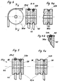
- the groove 41 for the working rope 24d is adapted to the cross section of the work rope, while the clamping groove 42 in Cross-section is wedge-shaped and the safety rope 324 - if below Tension - seized under high friction in the inner area of the clamping groove 42 is, as indicated for example in Fig.4a.
- a variant of a simple keyway as the clamping groove 42 is the structure gem. 4b shows a safety jacket 43 placed over the clamping groove 42 and carries the safety rope 324 as long as it is without force on the roller 36a is applied. However, as soon as - after breaking the working rope 24d - the safety rope 324 takes over the function of the work rope, the slightly brittle or elastic one Safety sheath 43 the way for the safety rope to seize Release 324 into the clamping groove 42.
- a securing sheath can also be used in the construction according to FIG 43 according to FIG. 4b.
- wedge brake 45 between the two rollers fixed to the housing and is used in the case of a fuse because the safety cable 324 is tensioned and in the keyway 46 of the brake einfrisst.
- This wedge brake 45 may replace those described above Braking options according to Fig. 5.
- a pressure roller 47 is provided which spring-loads the safety rope 324 pushes into the unbraked position. The spring force that the pressure roller 47 applied is so low that it with a slight increase in voltage is overcome on the safety rope 324 and the safety rope 324 in the keyway 46.
- two working cables 24d run in parallel, one by one central safety rope 324 are accompanied.
- a seesaw 48 on which the three ropes 24d and 324 are attached, enables optimal length compensation and prevents that in the event of a break in the working rope 24d, an unequal load occurs on an invisible counterweight.
- the three shown Deflection rollers 36a could preferably also be formed in one piece.
- rocker 48 In the case of only two working ropes 24d without an additional safety rope 324 The rocker 48 also assumes a compensatory function in the event of a break one of the two working ropes 24d.
- FIGS. 9 and 10 show a safety cable 324, which is approximately vertical runs, e.g. as in the right area in Fig. 11 or in Fig. 8. So that this Cable 324 not inadvertently into the wedge brake 45 or its keyway 46 eats, it is spaced from the wedge brake by a spring-loaded roller 49 45 held. A leaf spring 50 generates the spring force.
- Fig. 11 shows an executed construction, as it e.g. at a bearing 54 with can be connected to a stand tube of a tripod.
- a pulley 52 on which, among other things, the safety rope 324 attacks.
- the pulley 52 comprises two pulley wheels 55 and 56, around which the cables are led. At least one of them is a safety cable 24f.
- a wedge brake 45 with pressure roller 47 is also assigned to these, around the safety cable in the event of a cable break in the pulley 24f slow down.
- a bearing 35 as not shown here, e.g. the support arm 2 and a Tare gear pivoted. Runs centrally through the camp 35 Cavity 51, which guides the cables from top to bottom.
- the pressure roller 47 is arranged, which is the non-tensioned safety rope 324 from the wedge brake 45. Presses only in the event of a fuse the rope 324 against the roller 47 or overcoming the force of the spring 50 in the keyway 46 in the key brake 45 and thus complicates the operation of the Tripod.
- a symbolically represented brake 57 enables the deflection roller to be blocked 36a and thereby fixing the tripod in position.
- Braking devices e.g. wedge brakes
- Limit switch 345 or 245 can be provided, which in the event of a fuse the voltage of the safety cable 324 responds and via connection cable 344 influences a circuit connected to it accordingly.
- Such a Circuit can e.g. optical or acoustic signals and / or brakes or the like. drive. For example, be provided that when using electromagnetic Brakes can not be opened or in the braking position go.
- FIGS. 13 and 13a one is in the event of a fuse (i.e. break of one of the two cables 24d) pivotable rocker 48 is provided.
- the pivoting movement of the rocker 48 is limited by a stop 148, so that the rope 24d which then becomes the safety rope 324 is not too far can yield.
- the rocker 48 helps, any small differences in length balance, so that the two cables 24d in the operating state carry the same load.
Landscapes
- Physics & Mathematics (AREA)
- General Physics & Mathematics (AREA)
- Optics & Photonics (AREA)
- Braking Arrangements (AREA)
- Microscoopes, Condenser (AREA)
- Tension Adjustment In Filamentary Materials (AREA)
Abstract
Description
- Fig.1 -
- Das Prinzip eines Stativs mit Tragarm, Gleitschuh, Seilzug und parallel geführtem Sicherungs-Seilzug;
- Fig.1a -
- eine Variante mit Federzug;
- Fig.2 -
- den normalen Arbeitszustand des Aufbaus gem. Fig.1, in perspektivi- scher Ansicht;
- Fig.3 -
- den gesicherten Zustand des Aufbaues gemäss Fig.1, mit gerissenem Arbeitsseil;
- Fig.4 -
- eine Umlenkrolle mit den zwei Seilen;
- Fig.4a -
- ein Detail aus Fig.4;
- Fig.4b
- eine Variante zu Fig.4a;
- Fig.5 und 5a -
- eine mehrteilige Variante Umlenkrolle
- Fig.6 und 6a -
- einen alternativen Aufbau mit einer Keilbremse, die nicht mit den Umlenkrollen verbunden ist;
- Fig.7 und 7a -
- einen vergleichbaren Aufbau zu Fig.6 und 6a mit an einem vertikal verlaufenden Seilzug angeordneten Klemmelement
- Fig.8 -
- eine weitere Variante zur zusätzlichen Erhöhung der Sicherheit bei einem Aufbau, bei welchem der Ausgleich mit mehreren Seilen vorgenommen wird;
- Fig.9 und 9a -
- eine Seilbremse in Betriebs- bzw. Sicherungsstellung;
- Fig.10 -
- eine Seilbremse für das Sicherungsseil; in perspektivischer Ansicht;
- Fig.11 -
- einen Längsschnitt durch einen Tragarm mit Seil und Flaschenzug;
- Fig.12 und 12a -
- eine Variante mit einem elektrischen Endschalter für die Signalabgabe und/oder Steuerung der Bremse im Sicherungsfall und
- Fig.13 und 13a -
- eine Variante zum Aufbau nach Fig.8, bei der lediglich zwei Arbeitsseile 24d vorgesehen sind, die grundsätzlich immer gespannt sind.
Bei solchen Ausführungsformen wirken die Sensoren in umgekehrter Richtung als bei reinen Sicherungsseilen. Bei letzteren detektieren sie den Aufbau einer Spannung, bei ersteren detektieren Sie den Abfall einer Spannung im Seil (Bruch).
- 2 -
- Tragarm bzw. Parallelogrammträger
- 22 -
- Ausgleichsarm
- 23 -
- Gleitschuh
- 24 -
- Seilzug
- 24d
- Arbeitsseilzug
- 24f
- Sicherungsseilzug
- 29a -
- Tragarm
- 35 -
- Lager
- 36, 36a -
- Rolle
- 37, 37a -
- Rolle
- 38 -
- Drehbarer Teil der Umlenkrolle 37a
- 39 -
- Starrer oder gebremster Teil der Umlenkrolle 37a
- 40 -
- Zugfeder
- 41 -
- Nut
- 42 -
- Klemm- bzw. Sicherungsnut (keilförmig)
- 43 -
- Sicherungsmantel
- 44 -
- Achse
- 45 -
- Keilbremse
- 46 -
- Keilnut
- 47 -
- Andrück- bzw. Sicherungsrolle
- 48 -
- Wippe
- 49 -
- Rollenkörper
- 50 -
- Blattfeder
- 51 -
- Hohlraum
- 52 -
- Flaschenzug
- 55 -
- Flaschenzugrollen
- 56 -
- Flaschenzugrollen
- 57 -
- Bremse; (vergleichbare Bremsen können auf allen Bewegungsachsen des Stativs, vorzugsweise im Tragarm 2 (Parallelogrammträger) oder im Schwenkträger 79 vorgesehen sein;)
- 245 -
- Endschalter
- 324 -
- Sicherungsseil
- 344 -
- Anschlusskabel
- 345 -
- Endschalter
- AGb -
- Ausgleichsgewicht
- G -
- Last bzw. Gewicht des Mikroskops
- F -
- konstante Ausgleichskraft
Claims (10)
- Stativ mit einem schwenkbaren Tragarm (2) für die Aufnahme einer Last (G) und mit einer Ausgleichskraft (FA), die über einen Arbeitsseilzug (24) auf den Tragarm (2) wirkt, dadurch gekennzeichnet, dass dem Seilzug (24) ein Sicherungsseilzug (324) zur Seite gestellt ist, dessen Seil (324) im Sicherungsfall die Funktion des Arbeitsseilzugs (24) übernimmt.
- Stativ mit einem Tragarm (2) für die Aufnahme einer Last (G) und mit einer Ausgleichskraft (FA), die über einen Arbeitsseilzug auf den Tragarm (2) wirkt, dadurch gekennzeichnet, dass der Sicherungsseilzug (324) im Gebrauchszustand spannungslos, im Sicherungszustand jedoch unter Spannung verläuft.
- Stativ nach Anspruch 1 oder 2, dadurch gekennzeichnet, dass die beiden Seilzüge (24, 324) im Betriebszustand im wesentlichen parallel zueinander verlaufen und dem Sicherungsseilzug (324) eine Bremseinrichtung (39; 42; 42a; 45) zugeordnet ist, die im Fall eines Wechsels vom Arbeitsseil (24d) auf das Sicherungsseil (324) in Kraft tritt und dem Bewegen des Sicherungsseils (324) oder eines anderen bewegbaren Bauteils des Stativs einen Widerstand entgegensetzt, der zu einem erhöhten Widerstand gegen das Bewegen der Last (G) führt.
- Stativ nach einem der vorhergehenden Ansprüche, dadurch gekennzeichnet, dass dem Sicherungsseil (324) wenigstens ein elektrischer oder elektronischer Schalter (245; 345) zugeordnet ist, der im Sicherungsfall durch das Sicherungsseil (324) direkt oder indirekt betätigbar ist und der Schalter (245; 345) mit Signalgebern und/oder Steuerungen und/oder elektromagnetischen Bremsen (57) zur Ansteuerung derselben verbunden ist.
- Stativ nach einem der vorhergehenden Ansprüche dadurch gekennzeichnet, dass die beiden Seilzüge (24, 324) wenigstens um eine Umlenkrolle (36a) geführt sind, die parallele Umfangsnuten (41, 42) für beide Seilzüge (24; 324) aufweisen, wobei die Umfangsnut für das Sicherungsseil (324) als Klemmnut (42) ausgebildet ist, in die sich das Sicherungsseil (324) unter Zugbelastung (im Sicherungsfall) hineinfrisst, sodass es zu einer erhöhten Reibung zwischen Sicherungsseil (324) und den Wandungen der Nut (42) kommt.
- Stativ nach einem der vorhergehenden Ansprüche, dadurch gekennzeichnet, dass wenigstens eine Umlenkrolle (37a) zweiteilig ausgebildet ist und über einen rotierbaren Teil (38) und einen ggf. gebremst rotierbaren oder starren Teil (39) verfügt, wobei zwischen dem rotierbaren (38) und dem schlecht oder nicht rotierbaren Teil (39) eine Klemmnut (42a) für das Sicherungsseil (324) derart ausgebildet ist, dass beim Auftreten einer Zugspannung am Sicherungsseil (324) sich dieses in die Klemmnut (42a) frisst und die beiden Teile (38, 39) im Sicherungsfall durch Spreizung gegen Federkraft auseinander verschiebbar sind, wobei dem einen Teil (39) eine Bremseinrichtung zur Seite gestellt ist.
- Stativ nach einem der vorhergehenden Ansprüche, dadurch gekennzeichnet, dass im Normalbetrieb die Klemmnut (42; 42a) für das Sicherungsseil (324) durch einen Sicherungsmantel (43) abgedeckt ist, der das ungespannte Sicherungsseil (324) stützt, der jedoch im Falle einer erhöhten Zugspannung am Sicherungsseil (324) kollabiert oder bricht und das Einfressen des Sicherungsseils (324) in der Nut (42; 42a) ermöglicht.
- Stativ nach einem der vorhergehenden Ansprüche, dadurch gekennzeichnet, dass ein Bremselement (45) vorgesehen ist, das eine Klemmnut (46) aufweist, die so über dem Sicherungsseil (324) platziert ist, dass im unbelasteten Zustand des Sicherungsseils (324) keine Berührung zwischen Klemmnut (46) und Sicherungsseil (324) stattfindet, dass jedoch im Falle einer am Sicherungsseil (324) angreifenden Zuglast das Sicherungsseil (324) in Klemmkontakt mit der Klemmnut (46) kommt.
- Stativ nach einem der vorhergehenden Ansprüche, dadurch gekennzeichnet, dass wenigstens zwei parallele Arbeitsseile (24d) und mindestens ein dazu parallel geführtes Sicherungsseil (324) vorgesehen sind, wobei zum optimalen Längenausgleich zwischen den mindestens drei Seilen (24d; 324) eine Wippe (48) vorgesehen ist, welche die Anfangsenden der Arbeits- und Sicherungsseile (24, 324) aufnimmt.
- Stativ nach einem der vorhergehenden Ansprüche, dadurch gekennzeichnet, dass zur Aufnahme der Ausgleichskräfte wenigstens zwei Arbeitsseile (24d) vorgesehen sind, von denen jedes für die volle Ausgleichskraft ausgelegt ist, und dass jedem dieser Arbeitsseile (24d) wenigstens je ein Sensor (245; 345) zugeordnet ist, der den Übergang vom Arbeitszustand in den Sicherungszustand registriert und Informationen an den Anwender weiterleite und/oder Bremsen steuert.
Applications Claiming Priority (2)
| Application Number | Priority Date | Filing Date | Title |
|---|---|---|---|
| DE20019107U DE20019107U1 (de) | 2000-11-12 | 2000-11-12 | Stativ |
| DE20019107U | 2000-11-12 |
Publications (2)
| Publication Number | Publication Date |
|---|---|
| EP1207335A1 true EP1207335A1 (de) | 2002-05-22 |
| EP1207335B1 EP1207335B1 (de) | 2006-06-14 |
Family
ID=7948654
Family Applications (1)
| Application Number | Title | Priority Date | Filing Date |
|---|---|---|---|
| EP01125607A Expired - Lifetime EP1207335B1 (de) | 2000-11-12 | 2001-10-26 | Stativ |
Country Status (4)
| Country | Link |
|---|---|
| US (1) | US6691960B2 (de) |
| EP (1) | EP1207335B1 (de) |
| JP (1) | JP4130072B2 (de) |
| DE (2) | DE20019107U1 (de) |
Families Citing this family (14)
| Publication number | Priority date | Publication date | Assignee | Title |
|---|---|---|---|---|
| EP1193438B1 (de) * | 2000-09-28 | 2006-11-15 | Leica Microsystems Schweiz AG | Stativ |
| DE10142564A1 (de) † | 2000-09-30 | 2002-04-11 | Zeiss Carl | Stativ |
| DE20019107U1 (de) * | 2000-11-12 | 2001-01-25 | Leica Microsystems Ag, Heerbrugg | Stativ |
| DE20019106U1 (de) | 2000-11-12 | 2001-02-22 | Leica Microsystems Ag, Heerbrugg | Stativ mit Parallelogrammträger und Balanciermechanismus |
| DE20019105U1 (de) * | 2000-11-12 | 2001-05-23 | Leica Microsystems Ag, Heerbrugg | Stativ |
| US20040251390A1 (en) * | 2003-06-12 | 2004-12-16 | Mjm Industries, Inc. | Viewing system |
| JP2008501595A (ja) * | 2004-05-28 | 2008-01-24 | コーニンクレッカ フィリップス エレクトロニクス エヌ ヴィ | 重力補償装置 |
| US7293670B2 (en) * | 2004-09-08 | 2007-11-13 | Mhe Technologies, Inc. | Upper block |
| RU2492904C2 (ru) | 2007-11-08 | 2013-09-20 | Электроник Тиэте Контролз, Инк. | Системы подъемного узла и способы |
| GB2475298B (en) * | 2009-11-13 | 2016-08-10 | Kenex (Electro-Medical) Ltd | Medical equipment support |
| US10183850B2 (en) | 2012-12-21 | 2019-01-22 | Electronic Theatre Controls, Inc. | Compact hoist system |
| US10953536B2 (en) * | 2019-05-03 | 2021-03-23 | The Magstim Company Limited | Support arrangement for supporting a load in an elevated position |
| DE102020205565B4 (de) * | 2020-04-30 | 2022-05-12 | Sauer Gmbh | Werkzeugmaschine mit Kabelführungsvorrichtung |
| CN117481825B (zh) * | 2024-01-02 | 2024-03-29 | 首都医科大学附属北京天坛医院 | 血管介入手术机器人 |
Citations (16)
| Publication number | Priority date | Publication date | Assignee | Title |
|---|---|---|---|---|
| US3820752A (en) * | 1971-09-16 | 1974-06-28 | J Oram | Adjustable articulated support arm |
| DD221571A1 (de) | 1984-02-01 | 1985-04-24 | Zeiss Jena Veb Carl | Drehgelenk mit einer einrichtung zur kompensation unterschiedlicher lastmomente |
| US4515333A (en) * | 1980-04-15 | 1985-05-07 | University Of Technology | Adjustable support for an optical or other instrument |
| US4544121A (en) * | 1982-02-03 | 1985-10-01 | Tokyo Kogaku Kikai Kabushiki Kaisha | Support apparatus for medical appliance |
| DE3739080A1 (de) | 1987-11-01 | 1989-05-11 | Stemme Otto | Federvorrichtung zum gewichtausgleich fuer stative |
| EP0342560A2 (de) * | 1988-05-20 | 1989-11-23 | ARTEMIDE S.p.A. | Gestängeleuchte |
| US5253832A (en) | 1991-07-26 | 1993-10-19 | Bolas Mark T | Spring counterbalanced boom suspension system |
| US5397323A (en) | 1992-10-30 | 1995-03-14 | International Business Machines Corporation | Remote center-of-motion robot for surgery |
| WO1997013997A1 (de) | 1995-10-12 | 1997-04-17 | Leica Ag | Stativ |
| EP0866269A1 (de) | 1997-03-18 | 1998-09-23 | Abb Research Ltd. | Kesselanlage für eine Wärmeerzeugung |
| DE19742050A1 (de) | 1997-09-24 | 1999-03-25 | Zeiss Carl Fa | Stativ mit Gewichtsausgleich |
| US6070839A (en) | 1997-03-20 | 2000-06-06 | Carl-Zeiss-Stiftung Trading As Carl Zeiss | Stand |
| DE20019107U1 (de) * | 2000-11-12 | 2001-01-25 | Leica Microsystems Ag, Heerbrugg | Stativ |
| DE20019109U1 (de) | 2000-11-12 | 2001-02-22 | Leica Microsystems Ag, Heerbrugg | Stativ, insbesondere für Operationsmikroskope |
| DE20019106U1 (de) | 2000-11-12 | 2001-02-22 | Leica Microsystems Ag, Heerbrugg | Stativ mit Parallelogrammträger und Balanciermechanismus |
| DE20019105U1 (de) | 2000-11-12 | 2001-05-23 | Leica Microsystems Ag, Heerbrugg | Stativ |
Family Cites Families (7)
| Publication number | Priority date | Publication date | Assignee | Title |
|---|---|---|---|---|
| DE7930125U1 (de) * | 1979-07-24 | 1980-01-24 | Contraves Ag, Zuerich (Schweiz) | Zusatzvorrichtung an einem stativ fuer ein optisches beobachtungsgeraet |
| FR2551332B1 (fr) * | 1983-09-07 | 1987-04-17 | Alpia Sa | Dispositif de securite pour l'immobilisation d'une colonne de table a dessin |
| US4512106A (en) * | 1983-12-30 | 1985-04-23 | American Sterilizer Company | Cable failure indicator |
| DE9013260U1 (de) * | 1990-09-19 | 1990-11-22 | Fa. Carl Zeiss, 7920 Heidenheim | Tragvorrichtung mit Gewichtsausgleich für ein Operationsmikroskop |
| JPH066136B2 (ja) * | 1991-12-25 | 1994-01-26 | 佐原 今朝徳 | 医療用光学機器のスタンド装置 |
| US5551652A (en) * | 1994-03-28 | 1996-09-03 | Mcdonnell Douglas Corporation | Standby control system |
| US5538209A (en) * | 1994-05-24 | 1996-07-23 | Mcdonnell Douglas Corporation | Hardover protection system for an aircraft |
-
2000
- 2000-11-12 DE DE20019107U patent/DE20019107U1/de not_active Expired - Lifetime
-
2001
- 2001-10-26 DE DE50110136T patent/DE50110136D1/de not_active Expired - Lifetime
- 2001-10-26 EP EP01125607A patent/EP1207335B1/de not_active Expired - Lifetime
- 2001-11-08 US US10/007,168 patent/US6691960B2/en not_active Expired - Lifetime
- 2001-11-12 JP JP2001346607A patent/JP4130072B2/ja not_active Expired - Fee Related
Patent Citations (17)
| Publication number | Priority date | Publication date | Assignee | Title |
|---|---|---|---|---|
| US3820752A (en) * | 1971-09-16 | 1974-06-28 | J Oram | Adjustable articulated support arm |
| US4515333A (en) * | 1980-04-15 | 1985-05-07 | University Of Technology | Adjustable support for an optical or other instrument |
| US4544121A (en) * | 1982-02-03 | 1985-10-01 | Tokyo Kogaku Kikai Kabushiki Kaisha | Support apparatus for medical appliance |
| DD221571A1 (de) | 1984-02-01 | 1985-04-24 | Zeiss Jena Veb Carl | Drehgelenk mit einer einrichtung zur kompensation unterschiedlicher lastmomente |
| DE3739080A1 (de) | 1987-11-01 | 1989-05-11 | Stemme Otto | Federvorrichtung zum gewichtausgleich fuer stative |
| EP0342560A2 (de) * | 1988-05-20 | 1989-11-23 | ARTEMIDE S.p.A. | Gestängeleuchte |
| US5253832A (en) | 1991-07-26 | 1993-10-19 | Bolas Mark T | Spring counterbalanced boom suspension system |
| US5397323A (en) | 1992-10-30 | 1995-03-14 | International Business Machines Corporation | Remote center-of-motion robot for surgery |
| WO1997013997A1 (de) | 1995-10-12 | 1997-04-17 | Leica Ag | Stativ |
| US6129319A (en) * | 1995-10-12 | 2000-10-10 | Leica Microsystems Ag | Automatically adjustable counterbalanced stand |
| EP0866269A1 (de) | 1997-03-18 | 1998-09-23 | Abb Research Ltd. | Kesselanlage für eine Wärmeerzeugung |
| US6070839A (en) | 1997-03-20 | 2000-06-06 | Carl-Zeiss-Stiftung Trading As Carl Zeiss | Stand |
| DE19742050A1 (de) | 1997-09-24 | 1999-03-25 | Zeiss Carl Fa | Stativ mit Gewichtsausgleich |
| DE20019107U1 (de) * | 2000-11-12 | 2001-01-25 | Leica Microsystems Ag, Heerbrugg | Stativ |
| DE20019109U1 (de) | 2000-11-12 | 2001-02-22 | Leica Microsystems Ag, Heerbrugg | Stativ, insbesondere für Operationsmikroskope |
| DE20019106U1 (de) | 2000-11-12 | 2001-02-22 | Leica Microsystems Ag, Heerbrugg | Stativ mit Parallelogrammträger und Balanciermechanismus |
| DE20019105U1 (de) | 2000-11-12 | 2001-05-23 | Leica Microsystems Ag, Heerbrugg | Stativ |
Also Published As
| Publication number | Publication date |
|---|---|
| US20020121578A1 (en) | 2002-09-05 |
| US6691960B2 (en) | 2004-02-17 |
| JP2002219134A (ja) | 2002-08-06 |
| EP1207335B1 (de) | 2006-06-14 |
| JP4130072B2 (ja) | 2008-08-06 |
| DE50110136D1 (de) | 2006-07-27 |
| DE20019107U1 (de) | 2001-01-25 |
Similar Documents
| Publication | Publication Date | Title |
|---|---|---|
| EP0730107B1 (de) | Scheibenbremse | |
| EP1207335B1 (de) | Stativ | |
| DE69730767T2 (de) | Bremse für Hebegerät | |
| DE3003119C2 (de) | Vorrichtung zur Blockierung der Arbeitsfläche eines Zeichentisches | |
| EP2978702B1 (de) | Bremsvorrichtung für eine aufzugsanlage | |
| DE102013111385A1 (de) | Auslösevorrichtung einer Fangvorrichtung für eine Aufzugskabine einer Aufzugsanlage | |
| DE4033398A1 (de) | Gelenkkopf fuer eine kamera oder dergleichen | |
| DE19906073C2 (de) | Vorrichtung zum Verhindern unkontrollierter Beschleunigungen eines Fahrkorbs einer Aufzugsanlage | |
| EP0150701B1 (de) | Kuppelklemme | |
| EP1207334A1 (de) | Stativ | |
| DE102012012245A1 (de) | Ausrichtvorrichtung einer Prüfvorrichtung | |
| DE19818688C1 (de) | Vollgekapseltes Abseilgerät mit zwei Wirkungsrichtungen | |
| DE2400198A1 (de) | Sicherheitsbremse | |
| EP0899231A1 (de) | Bremsfangvorrichtung | |
| EP4077190A1 (de) | Fangvorrichtung für einen aufzug | |
| DE2219127A1 (de) | Vorrichtung zum Abspulen eines Seils unter Spannung von einer Trommel | |
| DE2160935A1 (de) | Bremsvorrichtung | |
| EP1207336A1 (de) | Stativ mit Parallelogrammträger und Balanciermechanismus | |
| DE102007052280A1 (de) | Richtungsunabhängig ansprechender Geschwindigkeitsbegrenzer | |
| DE3642956A1 (de) | Stativ mit einer saeule und einem ueber ein gelenk damit verbundenen ausleger | |
| WO2008128556A1 (de) | Haltevorrichtung für medizinisch-optische ausrüstung, insbesondere für monitor | |
| DE102004027984B4 (de) | Elastische Lagerung einer Brems- und Klemmeinrichtung | |
| EP1205703A2 (de) | Stativ, insbesondere für Operationsmikroskope | |
| EP1483530B1 (de) | Stativkopf, insbesondere kamerastativkopf | |
| WO2019185569A1 (de) | Zangenbremse für eine aufzugsanlage, die insbesondere als halte- und sicherheitsbremse dient |
Legal Events
| Date | Code | Title | Description |
|---|---|---|---|
| PUAI | Public reference made under article 153(3) epc to a published international application that has entered the european phase |
Free format text: ORIGINAL CODE: 0009012 |
|
| AX | Request for extension of the european patent |
Free format text: AL;LT;LV;MK;RO;SI |
|
| 17P | Request for examination filed |
Effective date: 20021031 |
|
| R17P | Request for examination filed (corrected) |
Effective date: 20021031 |
|
| AKX | Designation fees paid |
Designated state(s): DE FR GB |
|
| 17Q | First examination report despatched |
Effective date: 20041217 |
|
| GRAP | Despatch of communication of intention to grant a patent |
Free format text: ORIGINAL CODE: EPIDOSNIGR1 |
|
| GRAS | Grant fee paid |
Free format text: ORIGINAL CODE: EPIDOSNIGR3 |
|
| GRAA | (expected) grant |
Free format text: ORIGINAL CODE: 0009210 |
|
| AK | Designated contracting states |
Kind code of ref document: B1 Designated state(s): DE FR GB |
|
| REG | Reference to a national code |
Ref country code: GB Ref legal event code: FG4D Free format text: NOT ENGLISH |
|
| REF | Corresponds to: |
Ref document number: 50110136 Country of ref document: DE Date of ref document: 20060727 Kind code of ref document: P |
|
| GBT | Gb: translation of ep patent filed (gb section 77(6)(a)/1977) |
Effective date: 20060924 |
|
| ET | Fr: translation filed | ||
| PLBE | No opposition filed within time limit |
Free format text: ORIGINAL CODE: 0009261 |
|
| STAA | Information on the status of an ep patent application or granted ep patent |
Free format text: STATUS: NO OPPOSITION FILED WITHIN TIME LIMIT |
|
| 26N | No opposition filed |
Effective date: 20070315 |
|
| REG | Reference to a national code |
Ref country code: GB Ref legal event code: 732E Free format text: REGISTERED BETWEEN 20100304 AND 20100310 |
|
| REG | Reference to a national code |
Ref country code: FR Ref legal event code: CD |
|
| REG | Reference to a national code |
Ref country code: FR Ref legal event code: TP |
|
| REG | Reference to a national code |
Ref country code: FR Ref legal event code: PLFP Year of fee payment: 15 |
|
| PGFP | Annual fee paid to national office [announced via postgrant information from national office to epo] |
Ref country code: DE Payment date: 20151030 Year of fee payment: 15 |
|
| REG | Reference to a national code |
Ref country code: FR Ref legal event code: PLFP Year of fee payment: 16 |
|
| PGFP | Annual fee paid to national office [announced via postgrant information from national office to epo] |
Ref country code: FR Payment date: 20161027 Year of fee payment: 16 Ref country code: GB Payment date: 20161028 Year of fee payment: 16 |
|
| REG | Reference to a national code |
Ref country code: DE Ref legal event code: R119 Ref document number: 50110136 Country of ref document: DE |
|
| PG25 | Lapsed in a contracting state [announced via postgrant information from national office to epo] |
Ref country code: DE Free format text: LAPSE BECAUSE OF NON-PAYMENT OF DUE FEES Effective date: 20170503 |
|
| GBPC | Gb: european patent ceased through non-payment of renewal fee |
Effective date: 20171026 |
|
| REG | Reference to a national code |
Ref country code: FR Ref legal event code: ST Effective date: 20180629 |
|
| PG25 | Lapsed in a contracting state [announced via postgrant information from national office to epo] |
Ref country code: GB Free format text: LAPSE BECAUSE OF NON-PAYMENT OF DUE FEES Effective date: 20171026 |
|
| PG25 | Lapsed in a contracting state [announced via postgrant information from national office to epo] |
Ref country code: FR Free format text: LAPSE BECAUSE OF NON-PAYMENT OF DUE FEES Effective date: 20171031 |