EP1206972A1 - Cleanable dispensing head and dispenser equipped therewith - Google Patents
Cleanable dispensing head and dispenser equipped therewith Download PDFInfo
- Publication number
- EP1206972A1 EP1206972A1 EP20010402792 EP01402792A EP1206972A1 EP 1206972 A1 EP1206972 A1 EP 1206972A1 EP 20010402792 EP20010402792 EP 20010402792 EP 01402792 A EP01402792 A EP 01402792A EP 1206972 A1 EP1206972 A1 EP 1206972A1
- Authority
- EP
- European Patent Office
- Prior art keywords
- dispensing
- dispensing head
- head according
- orifice
- product
- Prior art date
- Legal status (The legal status is an assumption and is not a legal conclusion. Google has not performed a legal analysis and makes no representation as to the accuracy of the status listed.)
- Granted
Links
Images


Classifications
-
- B—PERFORMING OPERATIONS; TRANSPORTING
- B65—CONVEYING; PACKING; STORING; HANDLING THIN OR FILAMENTARY MATERIAL
- B65D—CONTAINERS FOR STORAGE OR TRANSPORT OF ARTICLES OR MATERIALS, e.g. BAGS, BARRELS, BOTTLES, BOXES, CANS, CARTONS, CRATES, DRUMS, JARS, TANKS, HOPPERS, FORWARDING CONTAINERS; ACCESSORIES, CLOSURES, OR FITTINGS THEREFOR; PACKAGING ELEMENTS; PACKAGES
- B65D83/00—Containers or packages with special means for dispensing contents
- B65D83/14—Containers or packages with special means for dispensing contents for delivery of liquid or semi-liquid contents by internal gaseous pressure, i.e. aerosol containers comprising propellant for a product delivered by a propellant
- B65D83/34—Cleaning or preventing clogging of the discharge passage
- B65D83/345—Anti-clogging means for outlets
-
- B—PERFORMING OPERATIONS; TRANSPORTING
- B05—SPRAYING OR ATOMISING IN GENERAL; APPLYING FLUENT MATERIALS TO SURFACES, IN GENERAL
- B05B—SPRAYING APPARATUS; ATOMISING APPARATUS; NOZZLES
- B05B1/00—Nozzles, spray heads or other outlets, with or without auxiliary devices such as valves, heating means
- B05B1/34—Nozzles, spray heads or other outlets, with or without auxiliary devices such as valves, heating means designed to influence the nature of flow of the liquid or other fluent material, e.g. to produce swirl
- B05B1/3405—Nozzles, spray heads or other outlets, with or without auxiliary devices such as valves, heating means designed to influence the nature of flow of the liquid or other fluent material, e.g. to produce swirl to produce swirl
- B05B1/341—Nozzles, spray heads or other outlets, with or without auxiliary devices such as valves, heating means designed to influence the nature of flow of the liquid or other fluent material, e.g. to produce swirl to produce swirl before discharging the liquid or other fluent material, e.g. in a swirl chamber upstream the spray outlet
- B05B1/3421—Nozzles, spray heads or other outlets, with or without auxiliary devices such as valves, heating means designed to influence the nature of flow of the liquid or other fluent material, e.g. to produce swirl to produce swirl before discharging the liquid or other fluent material, e.g. in a swirl chamber upstream the spray outlet with channels emerging substantially tangentially in the swirl chamber
- B05B1/3431—Nozzles, spray heads or other outlets, with or without auxiliary devices such as valves, heating means designed to influence the nature of flow of the liquid or other fluent material, e.g. to produce swirl to produce swirl before discharging the liquid or other fluent material, e.g. in a swirl chamber upstream the spray outlet with channels emerging substantially tangentially in the swirl chamber the channels being formed at the interface of cooperating elements, e.g. by means of grooves
- B05B1/3436—Nozzles, spray heads or other outlets, with or without auxiliary devices such as valves, heating means designed to influence the nature of flow of the liquid or other fluent material, e.g. to produce swirl to produce swirl before discharging the liquid or other fluent material, e.g. in a swirl chamber upstream the spray outlet with channels emerging substantially tangentially in the swirl chamber the channels being formed at the interface of cooperating elements, e.g. by means of grooves the interface being a plane perpendicular to the outlet axis
-
- B—PERFORMING OPERATIONS; TRANSPORTING
- B05—SPRAYING OR ATOMISING IN GENERAL; APPLYING FLUENT MATERIALS TO SURFACES, IN GENERAL
- B05B—SPRAYING APPARATUS; ATOMISING APPARATUS; NOZZLES
- B05B11/00—Single-unit hand-held apparatus in which flow of contents is produced by the muscular force of the operator at the moment of use
- B05B11/0005—Components or details
-
- B—PERFORMING OPERATIONS; TRANSPORTING
- B65—CONVEYING; PACKING; STORING; HANDLING THIN OR FILAMENTARY MATERIAL
- B65D—CONTAINERS FOR STORAGE OR TRANSPORT OF ARTICLES OR MATERIALS, e.g. BAGS, BARRELS, BOTTLES, BOXES, CANS, CARTONS, CRATES, DRUMS, JARS, TANKS, HOPPERS, FORWARDING CONTAINERS; ACCESSORIES, CLOSURES, OR FITTINGS THEREFOR; PACKAGING ELEMENTS; PACKAGES
- B65D83/00—Containers or packages with special means for dispensing contents
- B65D83/14—Containers or packages with special means for dispensing contents for delivery of liquid or semi-liquid contents by internal gaseous pressure, i.e. aerosol containers comprising propellant for a product delivered by a propellant
- B65D83/28—Nozzles, nozzle fittings or accessories specially adapted therefor
Definitions
- the present invention relates to a dispensing head intended to equip a dispenser for a fluid product to be dispensed in the form of a jet or a spray, as well as a distributor provided with such a distribution head. More in particular, the invention relates to a dispensing head comprising means facilitating cleaning, in the event of blockage.
- a fluid distributor as targeted by the present invention, includes a reservoir containing the product to be dispensed, provided with one end open, on which is fixed a distribution member.
- a distribution member Such an organ of distribution can be a pump or a valve, surmounted by a distribution.
- a distribution head of this type must ensure in particular two functions. On the one hand, it must allow the user to order actuation of the dispensing member, to eject a dose of product outside of the tank. On the other hand, it must allow the product leaving the tank to a dispensing orifice.
- a dispensing orifice is in particular in the form of a nozzle, connected to the dispensing member via a supply duct with which the distribution head is provided.
- the distribution of product is then produced in the form of a more or less filiform jet, or the shape of a cloud of fine droplets, called a spray.
- the routing of product to the dispensing orifice can also be carried out by simple pressure on a compressible product tank.
- the distributor is equipped with a distribution valve, in addition to the product, the tank contains a gas under pressure to propel the product to be dispensed through the orifice of distribution.
- a distribution head for the distribution of a product liquid comprises a body provided with a supply conduit in communication with the product reservoir, this conduit opening onto a dispensing nozzle provided an outlet, of small section.
- a nozzle is a insert, fixed, during manufacture, on the dispensing head, so not removable.
- Such a clogging phenomenon can occur quite frequently, when the product is a solution or dispersion that dries easily in the open air.
- a dispensing head intended to equip a fluid dispenser under the form of a jet or spray, comprising: - a body provided with a supply duct in communication with a pump or valve stem of the distributor, and - a part mounted on said body, said part comprising a dispensing orifice can be removably placed in communication with the conduit inlet, said part being movable at will, relative to said body, in view cleaning the supply duct.
- document EP-A-0 726 096 describes a spray head in which the dispensing orifice is movable relative to a supply duct of product, ending in an annular vortex chamber leading to said dispensing orifice.
- the mobility of the dispensing orifice aims to make vary the divergence characteristics of the spray obtained. Access to this vortex chamber and / or supply ducts, for cleaning these last, is not possible.
- the invention relates to a dispensing head whose structure allows the assembly or reassembly of the nozzle relative to the conduit respectively supply, with a precise and reproducible adjustment, as well as with a reliable sealing.
- the invention relates to an improvement of a cleanable dispensing head, capable of ensuring, throughout its period of use, the production of a jet or a spray, in fine droplets of constant quality.
- the elastic support between the body and the element mobile carrying the dispensing orifice allows, after dismantling and cleaning the supply channel, to reposition it precisely in its initial position, by with respect to the terminal portion of the intake channel, thus ensuring perfect reproducibility of the distribution qualities, or even the qualities of spraying, from the dispensing head.
- the elastic means are arranged to so that they exert a restoring force, parallel to an axis of exit of the product (passing through the dispensing orifice).
- the dispensing orifice is formed in a nozzle spraying, integral, in particular with the mobile element.
- the inlet channel delimits, in cooperation with the movable element, when the latter is in the first position, a vortex chamber in communication with the dispensing orifice.
- the rest of the intake channel can be partially delimited by the movable element and, in part by the body.
- the vortex chamber is provided with a central pillar, commonly called “center-post”, delimiting in cooperation with the element mobile, when the latter is in the first position, said chamber vortex.
- a central pillar commonly called “center-post”
- Such a “center-post” generally cylindrical in shape, thus that such a vortex chamber are described, for example, in the document FR-A-2 698 854.
- a vortex chamber is a recess, located directly upstream of the distribution orifice and supplied by a plurality of conduits, forming part of the inlet channel, and opening tangentially into the whirlpool room.
- This vortex chamber, as well as the tangential conduits can be hollowed out on the body, and more precisely on a front face of the "center-post".
- the vortex chamber, as well as the tangential channels can be engraved on the mobile element, more precisely on its internal face, intended to come into contact with the body.
- Such a vortex chamber is able to impart to the product flow, just before crossing the dispensing orifice, a spiral acceleration movement convergent, which makes it possible to obtain a burst in droplets particularly fine product, after passing through said dispensing orifice.
- This effect is particularly useful, especially when using a precompression, or a distribution valve in combination with a gas compressed propellant, not soluble in the product.
- the valve can be an additional gas valve, well known in the art.
- the "center-post" is projecting from a surface of the body, located opposite the orifice of distribution.
- the elastic means can be integral with the movable element.
- the elastic means can advantageously consist of an elastically stretchable membrane, arranged, advantageously at a distance, all around the dispensing orifice, in particular in the form of an annular element.
- the elasticity of the membrane is such that when the movable member is in the first position, a portion of the movable element located inside of the ring delimited by the membrane and in which the orifice of the distribution, is in elastic support on the "center-post".
- the elastic means can be in solidarity with the body, and in particular be part of the “center-post”.
- the "Center-post” may be, at least in part, elastically compressible in a direction parallel to the product exit axis.
- the elastic means can advantageously be formed of an elastomeric material, chosen in particular in the group of thermoplastic polyester-urethane (AU) elastomers, polybutadiene (BR), bromobutyl (BIIR) or chlorobutyl (CIIR) rubbers, chlorinated polyethylene (CM), polyester-aramid copolymers (CPA), polyester-glycol (CPE), polychloroprene (CR), polyethylene copolymers chlorosulfonated (CSM), copolymers of ethylene and methyl acrylate (EAM), terpolymers of ethylene, propylene and a diene (EPDM), copolymers of ethylene and propylene (EPM), polyether-urethanes (EU), fluorocarbon co- or terpolymers (FKM, FPM), butyl rubber (IIR), polyisoprene (IR, NR), nitrile rubber (NBR), polyurethanes (PUR),
- AU thermoplastic polyester
- the dispensing head can be produced by bi-injection (or over-molding) of a thermoplastic elastomer forming the means elastic, and a non-elastomeric material, forming the rest of the head distribution.
- thermoplastic material is chosen, by example of polyethylene (LDPE / HDPE), styrene-butadiene block copolymers (SBS), propylene-ethylene copolymers (PP / PE), polypropylene (PP) or polyamides (PA), making it possible to make the means elastic in the form of a zone, in particular annular, of lesser thickness inside which the dispensing orifice is made, this zone of least thickness being able to deform elastically in a direction parallel to the axis of output of the product, when the movable element passes from the second to the first position.
- LDPE / HDPE polyethylene
- SBS styrene-butadiene block copolymers
- PP / PE propylene-ethylene copolymers
- PP polypropylene
- PA polyamides
- Sealing means may also be provided, so as to ensure a suitable seal between the body and the movable element, when the latter is in the first position.
- Such sealing means can be produced in the form of a system with bead / groove, arranged in particular, continuously, around the parts forming the supply channel.
- a bead can be produced on the body, suitable to cooperate with a complementary groove of the movable element, or vice versa, when the latter is in the first position.
- the sealing means can be produced in the form of a elastically compressible cord, similarly arranged around the parts forming the supply channel. This cord can be made alternately on the body or on the movable element, slightly prominently.
- the passage from the first position to the second of the movable element, and vice versa is made by a pivoting movement of the element movable around an axis perpendicular to the product exit axis.
- the mobile element can be articulated on said body using a hinge, in particular a film hinge or a pin hinge.
- hooking / locking means can be provided for reversibly locking the movable element in the first position.
- the invention also relates to an assembly for packaging and distribution of a product, in particular a cosmetic product, said assembly being surmounted a distribution element, in particular a pump or a valve, equipped a distribution head as defined above.
- this set includes a dispensing valve
- the product to be dispensed is advantageously conveyed to the valve by means of a propellant under pressure, acting directly or indirectly on the product contained in a reservoir, in communication with said valve, which is provided with the assembly.
- the dispensing head of the invention is shaped as a push button having a bearing surface, on which the user presses to cause the ejection of a dose of product.
- distribution 1 comprises a cylindrical tank 2, of the metal canister type, with an axis X, in which a liquid product is conditioned, such as a hair spray.
- the tank 2 is pressurized, in particular using a propellant of the type liquefiable or compressed.
- the reservoir 2 has, in a conventional manner, a cylindrical body, a closed bottom 4 and a rolled edge 6, defining on its upper part a circular opening.
- a valve holder cup 8 (see figure 2).
- the cup 8 forms in its center a cylindrical dome 10, in which the body of a distribution valve is mounted 12.
- the cylindrical dome 10 is surrounded by an annular zone in depression 11.
- a first end of the valve 12 comprises an actuating rod 14, emerging outside, and passing through the center of the cup 8, at the dome 10.
- the axis of the actuating rod 14 coincides with the axis X of the tank.
- the second end of the valve extends by a dip tube 16 extending substantially to the bottom 4 of the container.
- the dip tube allows the product contained in the tank to be conveyed to the valve 12.
- the valve used can be a push-in type valve, male or female, or a valve actuated by lateral tilting of the valve stem 14.
- a dispensing head 18 is mounted on the free end of the valve stem 14, made in two parts 20, 30.
- a first part 20 forms the body of the head distribution 18.
- the free end of the valve stem 14 is engaged in the body.
- the body 20 comprises tubular connection means 22a intended to force-fit the body 20 onto the valve stem 14.
- the portion 22a constitutes an end portion of the channel 50.
- the channel 50 conveys the product from the valve stem to a dispensing orifice 32, like this will be detailed later.
- a pivoting element 30 On the body 20 is mounted, movably between a first position or closed position ( Figures 1, 4 and 5) and a second position or open position ( Figure 2), a pivoting element 30.
- this pivoting element 30 is practiced the distribution orifice 32, in communication with the supply channel 50.
- the movable element 30 is attached to the body 20 and articulated on the latter by a pin hinge 36a / 36b.
- a pivot axis Z is defined by the pins 36a.
- the movable element 30 constitutes an opening and closing member, of which the opening provides access to the different parts of the inlet channel 50 of the dispensing head 18, as well as on the inner face of the dispensing orifice 32.
- the supply channel 50 is partly defined, on the one hand by the body 20, and on the other hand by the movable element 30.
- the movable element 30 has the general shape of an “L” element, having a substantially flat front face 31, one lower end of which bears laterally the pins 36a of the hinge. Opposite the hinge, the face front 31 is connected to a plate 37, oriented perpendicular to the face front 31. The plate 37 ends in a folded portion 38 whose orientation is substantially parallel to face 31.
- the front face 31 of the movable element 30 comprises a spray nozzle 34, generally circular in shape.
- the center of the nozzle 34 is drilled, so that form the dispensing orifice 32.
- the spraying orifice 32 is a cylindrical hole, with a diameter of about 0.15 mm to about 1 mm.
- the depth of this dispensing orifice 32 is from about 0.1 mm to about 1 mm.
- the nozzle 34 is connected to the rest of the movable element 30 by elastic means 40, materialized, according to the embodiment considered, by an annular zone 41.
- This annular zone 41 can be made of an elastically material stretchable.
- the nozzle itself, that is to say the portion 34 in which is the dispensing orifice is made of a substantially rigid material or semi-rigid.
- the annular zone 41 surrounding it can be made of a material elastomeric thermoplastic, for example by bi-injection on a non-material elastomeric, in particular rigid to semi-rigid, forming the rest of the element mobile 30.
- the nozzle 34 is somehow “suspended” in the movable element 30 by the annular zone 41, and is displaceable elastically in the direction of the normal of the plane of the front face 31.
- an elastic displacement of the nozzle 34 can be carried out in the direction of product exit direction Y through the dispensing orifice 32.
- the area annular 41 can be made of a single material with the movable element 30, especially in the form of a thinner membrane.
- a annular membrane 41 can form concentric undulations or a bellows ( Figure 3), favoring under stress, the elastic displacement of the orifice distribution 32 along the orientation of the Y axis, relative to the rest of the element mobile 30.
- a semi-rigid material such as polyethylene.
- the body 20 forms a base 20a defining a circular plate 20b.
- a cylindrical structure comprising a recess 21 shaped so that the movable element 30 can be housed there, when the element mobile 30 is in the first position or closed position.
- the base 20a is delimited by a peripheral skirt 20c, capable of sliding axially inside of the cup 8, when the valve 12 is actuated.
- the recess 21 has a front part 21a intended to receive the part front 31 of the movable element 30. It comprises an upper part 21b intended to receive the plate 37 of the movable element 30. It has a rear part 21c intended to receive the rear part 38 of the movable element 30.
- the front face 31 of it is pressed onto the front part 21a of the recess.
- the plate 37 is placed on the upper surface 21b of the recess 21.
- the portion folded 38 of the movable member 30 is housed on the rear face 21c.
- the part folded 38 thus constitutes hooking means ensuring the locking, reversibly, the movable member 30 in the first position.
- the plate 37 constitutes a bearing surface allowing the user, by axial pressure using a finger, to activate the dispensing valve 12.
- the plate 37 may include additional locking means 38a / 38b, as illustrated in FIG. 2.
- additional locking means 38a / 38b here consist of lateral pins 38a of the movable element 30, capable of cooperating, in the closed position of the assembly, with complementary hollow portions 38b, provided on the sides of the recess 21.
- the tubular connection means 22a to the valve stem 14 conduct the product, via part 22 of the supply channel 50, towards the upper surface 21b of the recess 21.
- the portion 22 opens into a portion of the channel substantially radial 23, extending by an axial duct 24 hollowed out in the front face 21a of the recess 21.
- the conduit 24 opens onto a annular portion 25 of the inlet channel.
- a central pillar or “center-post” 28 protrudes from the front face 21a of the recess 21.
- the “center-post” has a front face 28a, in the center of which is hollowed out a swirl chamber 27 of cross section circular.
- a plurality of channels 26 open tangentially to the vortex chamber 27, themselves in communication with the portion ring finger 25.
- the vortex chamber promotes, if necessary, a good mixture of the product and the propellant and gives the produces, during its distribution, a spiral movement, converging towards the center of the vortex chamber 27, opposite the dispensing orifice 32. It this results in an acceleration of the product as it passes through the orifice of distribution 32, and thus a splitting of the product into particles substantially homogeneous, allowing to obtain a good quality spray.
- the production of such a vortex chamber 27 is suitable, in particular, for spraying a product of low viscosity, put under pressure in the tank 2 in particular by a propellant gas which is not soluble in the product.
- the propellant gas can be chosen from compressed gases (CO 2 , nitrogen, compressed air), liquefied gases or their mixtures.
- sealing means 70a, 70b can be provided.
- Such sealing means can be produced in the form of a seal.
- sealing 70a made of an elastic material and surrounding all of the different portions of the inlet channel 50, including the vortex chamber 27.
- the seal 70a is slightly protruding and compresses when the movable element moves from the second position to the first.
- the elastic seal 70a can be replaced by a system comprising a bead and a complementary groove, arranged around the different portions forming the inlet channel.
- a bead 70a can be produced on the body 20, capable of cooperate with a complementary groove 70b, provided on the movable element 30 (see Figure 3), or vice versa, when the latter is in the first position.
- the distribution of a dose of product P is carried out, in a conventional manner.
- the actuation of the dispensing valve 12 can be carried out by simple pressure on the upper surface 37 of the dispensing head 18, when the valve is a push-in valve.
- the valve is actuated by pressing laterally on the head of distribution.
- product residues may remain hung in the inlet channels 50, and in particular in the chamber vortex 27, in particular in the vicinity of the dispensing orifice 32. Or after prolonged rest, for example by evaporation of a solvent which the product contains, or by oxidation of the product, the formation of dry residues occurs, risking blocking entirely or partially the inlet channel and / or the orifice distribution 32.
- a portion of the element's surface mobile 30 may include a non-slip profile.
- the different parts of the inlet channel 50, the vortex chamber 27 and the interior of the nozzle 34 becomes accessible, and can be cleaned.
- the two separated parts 20, 30 can then be cleaned, for example by mechanical removal of residues, or by rinsing, in particular with water under the tap.
- the mobile element 30 After drying, the mobile element 30 is repositioned on the body 20 by a pivoting movement in the direction of the arrow F 1 (FIG. 2), following a movement carried out in the opposite direction to the opening direction.
- F 1 the direction of the arrow
- the internal wall of the nozzle 34 In the closed position of the movable member 30 on the body 20, the internal wall of the nozzle 34 is pressed elastically against the front face 28a of the "center-post".
- the dispensing orifice 32 is permanently pressed, elastically, against the vortex chamber 27, by stretching the elastic membrane 40.
- the elastic support of the nozzle 34 on the body 20 of the dispensing head, and more precisely on the front face 28a of the "center-post", is symbolized in FIGS. 4 and 5 by the arrows F 2 .
- the dispensing orifice 32 is, after the operation cleaning the inlet channel or the nozzle, repositioned exactly in the initial position, relative to the vortex chamber 27, thus ensuring perfect reproducibility of the spraying qualities of the dispensing head 18.
- FIG. 6 illustrates a view in axial section of an embodiment of a dispensing head 18 ′, simplified compared to the embodiment described above.
- the dispensing head 18 ′ does not include a vortex chamber or a “center-post”.
- the different portions 22, 23, 24, of the supply channel 50 lead the product directly to the dispensing orifice 32.
- the internal face 31a of the movable element 30 is directly in elastic support, in the direction of the arrows F 2 , on a flat portion 21 a of the body 20.
- the dispensing orifice 32 is provided at center of a portion 34 connected to the movable element via a ring of elastically stretchable material 41 whose characteristics, in particular of stretchability, are chosen so that, in the mounted position of the movable element 30 on the body 20, the portion 34 is constrained elastically against the portion 21a of the body 20.
- the dispensing head 18 in which the vortex chamber 27 as well as the tangential channels 26 are hollowed out in an integral portion of the body 20, in the dispensing head 18 ", the vortex chamber 27 as well as the tangential channels 26 are hollowed out in the nozzle 34.
- the body 20 forms a flat front face 21a on which is pressed, elastically, the internal face 34a of the nozzle 34. On this internal face 34a are molded the vortex chamber 27 and the tangential channels 26.
- the internal face 34a is directly in elastic support, in the direction of the arrows F 2 , on a flat portion 21a of the body 20.
- the channels tangentials 26 are in communication with an annular channel 25 formed between the planar portion 21a of the body 20 and the annular membrane 41.
- the annular channel 25 communicates with the valve stem via the portions 22, 23 and 24 of the inlet channel 50.
- FIG. 8 Another embodiment of a dispensing head 118 is shown in the Figure 8.
- the structure of the dispensing head 118 is substantially similar to the structure of the dispensing head 18 of the first embodiment, described previously.
- the parts identical to those of FIGS. 1 to 5 bear the same reference numbers. Only the elements that differ will be described in detail later. The reference numbers of these elements have a number greater than 100.
- the dispensing head 118 comprises a body 120 provided with a front face 21a plane.
- the front face 21a is provided with an annular channel 25 surrounding a "Center-post" 28 of generally cylindrical shape.
- the “center-post” 28 has a composite structure. It has a circular section base 128b radially delimiting the inner portion of the annular channel 25.
- the base 128b came in one piece with the body 120 and made of a thermoplastic material relatively rigid. On the base 128b is arranged a zone 140 produced in a elastically compressible material.
- Elastically compressible area 140 is covered with a plate 128a intended to come into elastic abutment against the face internal frontal 31 of the movable element 130, when the latter is in position locked on the body 120.
- the elastically compressible zone 140 is compressed, so that the face apparent from the plate 128a comes into elastic contact with the movable element 130 and is located substantially at the front face 21a of the body.
- profiles capable of defining, with the movable element 130, the tangential channels 26 and the vortex chamber 27, so that the dispensing orifice 32 is centered thereon.
- the realization of the elastically compressible zone 140 of the “center-post” 28 can be carried out by any appropriate means, and in particular by multiple injection of an appropriate elastomeric material on a substantially rigid material, then of a substantially rigid material on the elastically compressible zone 140.
- the use and cleaning of the dispensing head 118 is carried out in a manner similar to the use and cleaning of the dispensing head 18, and presents the same benefits.
Abstract
Tête de distribution (18) pour l'actionnement d'un élément de distribution (12), notamment d'une valve, équipant un récipient (2) contenant un produit à distribuer, et la distribution du produit au travers d'au moins un orifice de distribution (32), ladite tête de distribution comprenant : a) un corps (20) délimitant au moins en partie un canal d'amenée (50), et destiné au montage de la tête sur le récipient (2), et b) un élément (30) dans lequel est ménagé ledit orifice de distribution (32), ledit élément étant mobile entre une première position dans laquelle l'orifice de distribution (32) est en communication avec le canal d'amenée (50) et une seconde position dans laquelle ladite communication est interrompue, des moyens élastiques (40) étant prévus pour, lorsque ledit élément (30) est dans la première position, assurer un appui élastique entre le corps (20) et ledit élément mobile (30). L'invention concerne également un distributeur (1) équipé de cette tête de distribution (18). <IMAGE>Dispensing head (18) for actuating a dispensing element (12), in particular a valve, equipping a container (2) containing a product to be dispensed, and dispensing the product through at least one dispensing orifice (32), said dispensing head comprising: a) a body (20) delimiting at least partially a supply channel (50), and intended for mounting the head on the container (2), and b ) an element (30) in which said dispensing orifice (32) is formed, said element being movable between a first position in which the dispensing orifice (32) is in communication with the supply channel (50) and a second position in which said communication is interrupted, elastic means (40) being provided for, when said element (30) is in the first position, ensuring elastic support between the body (20) and said movable element (30). The invention also relates to a dispenser (1) equipped with this dispensing head (18). <IMAGE>
Description
La présente invention a trait à une tête de distribution destinée à équiper un distributeur pour un produit fluide à distribuer sous la forme d'un jet ou d'un spray, ainsi qu'à un distributeur muni d'une telle tête de distribution. Plus particulièrement, l'invention se rapporte à une tête de distribution comportant des moyens facilitant le nettoyage, en cas de bouchage.The present invention relates to a dispensing head intended to equip a dispenser for a fluid product to be dispensed in the form of a jet or a spray, as well as a distributor provided with such a distribution head. More in particular, the invention relates to a dispensing head comprising means facilitating cleaning, in the event of blockage.
Généralement, un distributeur de fluide, tel que visé par la présente invention, comprend un réservoir contenant le produit à distribuer, pourvu d'une extrémité ouverte, sur laquelle est fixé un organe de distribution. Un tel organe de distribution peut être une pompe ou une valve, surmontée d'une tête de distribution. Une tête de distribution de ce type doit assurer notamment deux fonctions. D'une part, elle doit permettre à l'utilisateur de commander l'actionnement de l'organe de distribution, pour éjecter une dose de produit hors du réservoir. D'autre part, elle doit permettre d'acheminer le produit sortant du réservoir vers un orifice de distribution. Généralement, un tel orifice de distribution se présente notamment sous forme d'une buse, reliée à l'organe de distribution via un conduit d'amenée dont est pourvue la tête de distribution. La distribution du produit s'effectue ensuite sous forme d'un jet plus ou moins filiforme, ou bien sous la forme d'un nuage de fines gouttelettes, appelé spray. L'acheminement du produit vers l'orifice de distribution peut être effectué, également, par simple pression sur un réservoir de produit compressible. Lorsque le distributeur est équipé d'une valve de distribution, outre le produit, le réservoir contient un gaz sous pression pour propulser le produit à distribuer au travers de l'orifice de distribution.Generally, a fluid distributor, as targeted by the present invention, includes a reservoir containing the product to be dispensed, provided with one end open, on which is fixed a distribution member. Such an organ of distribution can be a pump or a valve, surmounted by a distribution. A distribution head of this type must ensure in particular two functions. On the one hand, it must allow the user to order actuation of the dispensing member, to eject a dose of product outside of the tank. On the other hand, it must allow the product leaving the tank to a dispensing orifice. Generally, such a dispensing orifice is in particular in the form of a nozzle, connected to the dispensing member via a supply duct with which the distribution head is provided. The distribution of product is then produced in the form of a more or less filiform jet, or the shape of a cloud of fine droplets, called a spray. The routing of product to the dispensing orifice can also be carried out by simple pressure on a compressible product tank. When the distributor is equipped with a distribution valve, in addition to the product, the tank contains a gas under pressure to propel the product to be dispensed through the orifice of distribution.
De manière classique, une tête de distribution pour la distribution d'un produit liquide, comporte un corps muni d'un conduit d'amenée en communication avec le réservoir de produit, ce conduit débouchant sur une buse de distribution pourvue d'un orifice de sortie, de faible section. Habituellement, une telle buse est une pièce rapportée, fixée, lors de la fabrication, sur la tête de distribution, de manière non amovible. Conventionally, a distribution head for the distribution of a product liquid, comprises a body provided with a supply conduit in communication with the product reservoir, this conduit opening onto a dispensing nozzle provided an outlet, of small section. Usually such a nozzle is a insert, fixed, during manufacture, on the dispensing head, so not removable.
Certains produits, notamment lorsqu'ils contiennent des résines, après une longue période d'inutilisation, ont tendance à colmater les canaux d'amenée de produit et/ou la buse de distribution, par exemple par des résidus secs de produit. Or, avec les distributeurs actuellement sur le marché, il est pratiquement impossible de déboucher ou de nettoyer la buse et/ou le conduit d'amenée, sans provoquer un endommagement de la tête de distribution, préjudiciable au fonctionnement ultérieur du distributeur.Certain products, especially when they contain resins, after long period of non-use, tend to clog the inlet channels of product and / or the dispensing nozzle, for example by dry product residue. However, with the distributors currently on the market, it is practically impossible to unclog or clean the nozzle and / or the supply duct, without damage to the dispensing head, which could be subsequent operation of the dispenser.
Un tel phénomène de colmatage peut se produire assez fréquemment, lorsque le produit est une solution ou une dispersion séchant facilement à l'air libre. On trouve de tels produits parmi les colles pulvérisées, ou les produits de conditionnement pour les cheveux et la peau, comme les laques pour cheveux ou les produits anti-solaires.Such a clogging phenomenon can occur quite frequently, when the product is a solution or dispersion that dries easily in the open air. We find such products among spray adhesives, or conditioning for hair and skin, such as hair sprays or anti-sun products.
Par le document FR-A-2 787 731, au nom de la demanderesse, on connaít une tête de distribution destinée à équiper un distributeur de produit fluide sous la forme d'un jet ou d'un spray, comportant : - un corps muni d'un conduit d'amenée en communication avec une tige de pompe ou de valve du distributeur, et - une pièce montée sur ledit corps, ladite pièce comportant un orifice de distribution pouvant être mis, de manière amovible, en communication avec le conduit d'amenée, ladite pièce étant mobile à volonté, par rapport audit corps, en vue d'effectuer le nettoyage du conduit d'amenée.By document FR-A-2 787 731, in the name of the plaintiff, we know a dispensing head intended to equip a fluid dispenser under the form of a jet or spray, comprising: - a body provided with a supply duct in communication with a pump or valve stem of the distributor, and - a part mounted on said body, said part comprising a dispensing orifice can be removably placed in communication with the conduit inlet, said part being movable at will, relative to said body, in view cleaning the supply duct.
Il s'est avéré que le réajustement après remontage de la buse sur le conduit d'amenée est difficile à effectuer, de sorte que l'obtention d'une qualité constante de spray, après nettoyage, soit difficile à assurer.It turned out that the readjustment after reassembly of the nozzle on the duct supply is difficult to perform, so obtaining consistent quality of spray, after cleaning, is difficult to insure.
Par ailleurs, le document EP-A-0 726 096 décrit une tête de pulvérisation dans laquelle l'orifice de distribution est mobile par rapport à un conduit d'amenée de produit, se terminant par une chambre tourbillonnaire annulaire débouchant sur ledit orifice de distribution. La mobilité de l'orifice de distribution a pour but de faire varier les caractéristiques de divergence du spray obtenu. L'accès à cette chambre tourbillonnaire et/ou aux conduits d'amenée, en vue du nettoyage de ces derniers, n'est pas possible.Furthermore, document EP-A-0 726 096 describes a spray head in which the dispensing orifice is movable relative to a supply duct of product, ending in an annular vortex chamber leading to said dispensing orifice. The mobility of the dispensing orifice aims to make vary the divergence characteristics of the spray obtained. Access to this vortex chamber and / or supply ducts, for cleaning these last, is not possible.
Aussi, est-ce un des objets de la présente invention que de fournir une tête de distribution qui soit nettoyable aisément, sans démontage compliqué. En particulier, l'invention vise une tête de distribution dont la structure, permet le montage ou respectivement le remontage de la buse par rapport au conduit d'amenée, avec un ajustement précis et reproductible, ainsi qu'avec une étanchéité fiable.It is therefore one of the objects of the present invention to provide a head for easy to clean distribution without complicated disassembly. In particular, the invention relates to a dispensing head whose structure allows the assembly or reassembly of the nozzle relative to the conduit respectively supply, with a precise and reproducible adjustment, as well as with a reliable sealing.
Ainsi, l'invention vise un perfectionnement d'une tête de distribution nettoyable, capable d'assurer durant toute sa durée d'utilisation, la production d'un jet ou d'un spray, en fines gouttelettes de qualité constante.Thus, the invention relates to an improvement of a cleanable dispensing head, capable of ensuring, throughout its period of use, the production of a jet or a spray, in fine droplets of constant quality.
Ces objets sont atteints en réalisant une tête de distribution pour l'actionnement
d'un élément de distribution, notamment d'une valve, équipant un récipient
contenant un produit à distribuer, et la distribution du produit au travers d'au
moins un orifice de distribution, ladite tête de distribution comprenant :
Grâce à la disposition de l'invention, l'appui élastique entre le corps et l'élément mobile portant l'orifice de distribution, permet, après démontage et nettoyage du canal d'amenée, de le repositionner précisément dans sa position initiale, par rapport à la portion terminale du canal d'amenée, assurant ainsi une reproductibilité parfaite des qualités de distribution, voire des qualités de pulvérisation, de la tête de distribution. Thanks to the arrangement of the invention, the elastic support between the body and the element mobile carrying the dispensing orifice, allows, after dismantling and cleaning the supply channel, to reposition it precisely in its initial position, by with respect to the terminal portion of the intake channel, thus ensuring perfect reproducibility of the distribution qualities, or even the qualities of spraying, from the dispensing head.
En effet, le positionnement exact de l'orifice de distribution est crucial pour l'obtention d'une qualité de spray donnée. La moindre inexactitude de repositionnement, par exemple après nettoyage, de l'orifice de distribution par rapport au canal d'amenée, conduira inévitablement à une altération des propriétés originales du spray. En effet, l'effet de variation des caractéristiques d'un spray est bien connu par l'homme du métier. Aussi, la modification volontaire des caractéristiques d'un spray, par variation de la géométrie de la zone du canal d'amenée adjacente à l'orifice de distribution, a été décrite dans le document EP-A-0 726 096, cité précédemment.Indeed, the exact positioning of the dispensing orifice is crucial for obtaining a given quality of spray. The slightest inaccuracy of repositioning, for example after cleaning, of the dispensing orifice by compared to the intake canal, will inevitably lead to a deterioration of the original properties of the spray. Indeed, the effect of variation of the characteristics of a spray is well known to those skilled in the art. Also, voluntary modification characteristics of a spray, by variation of the geometry of the channel area inlet adjacent to the dispensing orifice, has been described in document EP-A-0 726 096, cited above.
Selon un aspect important de l'invention, les moyens élastiques sont disposés de sorte qu'ils exercent une force de rappel, parallèle à un axe de sortie du produit (passant par l'orifice de distribution).According to an important aspect of the invention, the elastic means are arranged to so that they exert a restoring force, parallel to an axis of exit of the product (passing through the dispensing orifice).
De manière avantageuse, l'orifice de distribution est formé dans une buse de pulvérisation, solidaire, notamment de l'élément mobile.Advantageously, the dispensing orifice is formed in a nozzle spraying, integral, in particular with the mobile element.
Selon un mode de réalisation préféré, le canal- d'amenée délimite, en coopération avec l'élément mobile, lorsque ce dernier est dans la première position, une chambre tourbillonnaire en communication avec l'orifice de distribution. De même, une partie au moins du reste du canal d'amenée peut être délimitée en partie par l'élément mobile et, en partie par le corps.According to a preferred embodiment, the inlet channel delimits, in cooperation with the movable element, when the latter is in the first position, a vortex chamber in communication with the dispensing orifice. Likewise, at least part of the rest of the intake channel can be partially delimited by the movable element and, in part by the body.
Avantageusement, la chambre tourbillonnaire est pourvue d'un pilier central, appelé communément « center-post », délimitant en coopération avec l'élément mobile, lorsque ce dernier est dans la première position, ladite chambre tourbillonnaire. Un tel « center-post », de forme généralement cylindrique, ainsi qu'une telle chambre tourbillonnaire sont décrits, par exemple, dans le document FR-A-2 698 854.Advantageously, the vortex chamber is provided with a central pillar, commonly called "center-post", delimiting in cooperation with the element mobile, when the latter is in the first position, said chamber vortex. Such a "center-post", generally cylindrical in shape, thus that such a vortex chamber are described, for example, in the document FR-A-2 698 854.
Généralement, une chambre tourbillonnaire est un évidement, situé directement en amont de l'orifice de distribution et alimentée par une pluralité de conduits, faisant partie du canal d'amenée, et débouchant de façon tangentielle dans la chambre tourbillonnaire.Generally, a vortex chamber is a recess, located directly upstream of the distribution orifice and supplied by a plurality of conduits, forming part of the inlet channel, and opening tangentially into the whirlpool room.
Cette chambre tourbillonnaire, ainsi que les conduits tangentiels peuvent être creusés sur le corps, et plus précisément sur une face frontale du « center-post ».This vortex chamber, as well as the tangential conduits can be hollowed out on the body, and more precisely on a front face of the "center-post".
Alternativement, la chambre tourbillonnaire, ainsi que les canaux tangentiels peuvent être gravés sur l'élément mobile, en plus précisément sur sa face interne, destinée à venir en contact avec le corps.Alternatively, the vortex chamber, as well as the tangential channels can be engraved on the mobile element, more precisely on its internal face, intended to come into contact with the body.
Une telle chambre tourbillonnaire est apte à conférer au flux du produit, juste avant de traverser l'orifice de distribution, un mouvement d'accélération en spirale convergente, ce qui permet d'obtenir un éclatement en gouttelettes particulièrement fines du produit, après avoir traversé ledit orifice de distribution. Cet effet est particulièrement utile, notamment, lorsqu'on utilise une pompe à précompression, ou une valve de distribution en combinaison avec un gaz propulseur comprimé, non soluble dans le produit. Le cas échéant, la valve peut être une valve de prise de gaz additionnel, bien connue dans état de la technique.Such a vortex chamber is able to impart to the product flow, just before crossing the dispensing orifice, a spiral acceleration movement convergent, which makes it possible to obtain a burst in droplets particularly fine product, after passing through said dispensing orifice. This effect is particularly useful, especially when using a precompression, or a distribution valve in combination with a gas compressed propellant, not soluble in the product. If necessary, the valve can be an additional gas valve, well known in the art.
Selon un mode de réalisation particulièrement préféré, le « center-post » fait saillie par rapport à une surface du corps, située en regard de l'orifice de distribution.According to a particularly preferred embodiment, the "center-post" is projecting from a surface of the body, located opposite the orifice of distribution.
Conformément à un mode de réalisation, les moyens élastiques peuvent être solidaires de l'élément mobile. Aussi, les moyens élastiques peuvent avantageusement être constitués d'une membrane étirable élastiquement, disposée, avantageusement à distance, tout autour de l'orifice de distribution, notamment sous forme d'un élément annulaire. A cet effet, dans cette configuration, l'élasticité de la membrane est'telle que, lorsque l'élément mobile est dans la première position, une portion de l'élément mobile située à l'intérieur de l'anneau délimité par la membrane et dans laquelle est ménagé l'orifice de distribution, est en appui élastique sur le « center-post ». According to one embodiment, the elastic means can be integral with the movable element. Also, the elastic means can advantageously consist of an elastically stretchable membrane, arranged, advantageously at a distance, all around the dispensing orifice, in particular in the form of an annular element. To this end, in this configuration, the elasticity of the membrane is such that when the movable member is in the first position, a portion of the movable element located inside of the ring delimited by the membrane and in which the orifice of the distribution, is in elastic support on the "center-post".
Conformément à un autre mode de réalisation, les moyens élastiques peuvent être solidaires du corps, et faire, notamment, partie du « center-post ». Aussi, le « center-post » peut être, au moins en partie, élastiquement compressible dans une direction parallèle à l'axe de sortie du produit.According to another embodiment, the elastic means can be in solidarity with the body, and in particular be part of the “center-post”. Also, the "Center-post" may be, at least in part, elastically compressible in a direction parallel to the product exit axis.
Dans les deux configurations ci-dessus, les moyens élastiques peuvent avantageusement être formés d'un matériau élastomérique, choisi notamment dans le groupe des élastomères de polyester-uréthane thermoplastiques (AU), de polybutadiène (BR), des caoutchoucs bromobutyle (BIIR) ou chlorobutyle (CIIR), de polyéthylène chloré (CM), des copolymères de polyester-aramide (CPA), des copolymères de polyester-glycol (CPE), de polychloroprène (CR), de polyéthylène chlorosulfoné (CSM), des copolymères d'éthylène et d'acrylate de méthyle (EAM), des terpolymères d'éthylène, de propylène et d'un diène (EPDM), des copolymères d'éthylène et de propylène (EPM), des polyéther-uréthanes (EU), des co- ou terpolymères fluorocarbonés (FKM, FPM), de caoutchouc butyle (IIR), de polyisoprène (IR, NR), de caoutchouc nitrile (NBR), des polyuréthanes (PUR), des phényl- ou vinyl-méthylsilicones (PVMQ), des copolymères de styrène-butadiène (SBR), des copolymères-bloc de styrène-butadiène (SBS), des copolymères-bloc de styrène-butadiène-buthylène-styrène (SEBS), des copolymères-bloc de styrène-isoprène (SIS), des caoutchoucs synthétiques (SR), des polysulfures (TM), des caoutchoucs thermoplastiques (TPE), des dérivés de polyoléfines thermoplastiques élastomériques (TPO), des polyuréthanes thermoplastiques (TPU), des polyvinyl-silicones (VMQ), de latex de copolymères de butadiène-styrène-2-vinylpyridine (VP).In the two configurations above, the elastic means can advantageously be formed of an elastomeric material, chosen in particular in the group of thermoplastic polyester-urethane (AU) elastomers, polybutadiene (BR), bromobutyl (BIIR) or chlorobutyl (CIIR) rubbers, chlorinated polyethylene (CM), polyester-aramid copolymers (CPA), polyester-glycol (CPE), polychloroprene (CR), polyethylene copolymers chlorosulfonated (CSM), copolymers of ethylene and methyl acrylate (EAM), terpolymers of ethylene, propylene and a diene (EPDM), copolymers of ethylene and propylene (EPM), polyether-urethanes (EU), fluorocarbon co- or terpolymers (FKM, FPM), butyl rubber (IIR), polyisoprene (IR, NR), nitrile rubber (NBR), polyurethanes (PUR), phenyl- or vinyl-methylsilicones (PVMQ), styrene-butadiene copolymers (SBR), styrene-butadiene block copolymers (SBS), block copolymers of styrene-butadiene-butethylene-styrene (SEBS), block copolymers of styrene-isoprene (SIS), synthetic rubbers (SR), polysulfides (TM), thermoplastic rubbers (TPE), derivatives of elastomeric thermoplastic polyolefins (TPO), polyurethanes thermoplastics (TPU), polyvinyl silicones (VMQ), latex copolymers butadiene-styrene-2-vinylpyridine (VP).
D'un point de vue pratique, la tête de distribution peut être réalisée par bi-injection (ou de surmoùlage) d'un élastomère thermoplastique formant les moyens élastiques, et d'un matériau non élastomérique, formant le reste de la tête de distribution.From a practical point of view, the dispensing head can be produced by bi-injection (or over-molding) of a thermoplastic elastomer forming the means elastic, and a non-elastomeric material, forming the rest of the head distribution.
Il est possible, également, de réaliser la tête de distribution en un seul matériau plastique. Dans ce cas, on choisit un matériau thermoplastique approprié, par exemple du polyéthylène (PEBD/PEHD), des copolymères-bloc de styrène-butadiène (SBS), des copolymères de propylène-éthylène (PP/PE), du polypropylène (PP) ou des polyamides (PA), permettant de réaliser les moyens élastiques sous la forme d'une zone, notamment annulaire, de moindre épaisseur à l'intérieur de laquelle est pratiqué l'orifice de distribution, cette zone de moindre épaisseur étant apte à se déformer élastiquement dans une direction parallèle à l'axe de sortie du produit, lorsque l'élément mobile passe de la seconde à la première position.It is also possible to make the dispensing head from a single material plastic. In this case, an appropriate thermoplastic material is chosen, by example of polyethylene (LDPE / HDPE), styrene-butadiene block copolymers (SBS), propylene-ethylene copolymers (PP / PE), polypropylene (PP) or polyamides (PA), making it possible to make the means elastic in the form of a zone, in particular annular, of lesser thickness inside which the dispensing orifice is made, this zone of least thickness being able to deform elastically in a direction parallel to the axis of output of the product, when the movable element passes from the second to the first position.
Des moyens d'étanchéité peuvent, en outre, être prévus, de manière à assurer une étanchéité convenable entre le corps et l'élément mobile, lorsque ce dernier se trouve dans la première position.Sealing means may also be provided, so as to ensure a suitable seal between the body and the movable element, when the latter is in the first position.
De tels moyens d'étanchéité peuvent être réalisés sous forme d'un système à bourrelet/gorge, disposé notamment, de manière continue, autour des parties formant le canal d'amenée. Ainsi, un bourrelet peut être réalisé sur le corps, apte à coopérer avec une gorge complémentaire de l'élément mobile, ou vice versa, lorsque ce dernier est dans la première position.Such sealing means can be produced in the form of a system with bead / groove, arranged in particular, continuously, around the parts forming the supply channel. Thus, a bead can be produced on the body, suitable to cooperate with a complementary groove of the movable element, or vice versa, when the latter is in the first position.
Alternativement, les moyens d'étanchéité peuvent être réalisés sous forme d'un cordon élastiquement compressible, disposé de manière similaire autour des parties formant le canal d'amenée. Ce cordon peut être réalisé alternativement sur le corps ou sur l'élément mobile, de manière légèrement proéminente.Alternatively, the sealing means can be produced in the form of a elastically compressible cord, similarly arranged around the parts forming the supply channel. This cord can be made alternately on the body or on the movable element, slightly prominently.
De manière avantageuse, le passage de la première position à la seconde de l'élément mobile, et vice versa, se fait par un mouvement de pivot de l'élément mobile autour d'un axe perpendiculaire à l'axe de sortie du produit. Dans ce cas, l'élément mobile peut être articulé sur ledit corps à l'aide d'une charnière, notamment une charnière film ou une charnière à tourillons.Advantageously, the passage from the first position to the second of the movable element, and vice versa, is made by a pivoting movement of the element movable around an axis perpendicular to the product exit axis. In that case, the mobile element can be articulated on said body using a hinge, in particular a film hinge or a pin hinge.
Avantageusement encore, des moyens d'accrochage/verrouillage peuvent être prévus pour verrouiller de façon réversible l'élément mobile dans la première position. Advantageously also, hooking / locking means can be provided for reversibly locking the movable element in the first position.
L'invention a encore pour objet un ensemble pour le conditionnement et la distribution d'un produit, notamment cosmétique, ledit ensemble étant surmonté d'un élément de distribution, notamment d'une pompe ou d'une valve, équipé d'une tête de distribution telle que définie précédemment.The invention also relates to an assembly for packaging and distribution of a product, in particular a cosmetic product, said assembly being surmounted a distribution element, in particular a pump or a valve, equipped a distribution head as defined above.
Lorsque cet ensemble comporte une valve de distribution, le produit à distribuer est acheminé vers la valve, avantageusement, au moyen d'un gaz propulseur sous pression, agissant directement ou indirectement sur le produit contenu dans un réservoir, en communication avec ladite valve, dont est pourvu l'ensemble.When this set includes a dispensing valve, the product to be dispensed is advantageously conveyed to the valve by means of a propellant under pressure, acting directly or indirectly on the product contained in a reservoir, in communication with said valve, which is provided with the assembly.
Avantageusement, la tête de distribution de l'invention est conformée en bouton-poussoir présentant une surface d'appui, sur laquelle l'utilisateur appuie pour provoquer l'éjection d'une dose de produit.Advantageously, the dispensing head of the invention is shaped as a push button having a bearing surface, on which the user presses to cause the ejection of a dose of product.
Pour mieux faire comprendre l'objet de l'invention, on va en décrire par la suite, à titre purement illustratif et non limitatif, des exemples de réalisation préférés de l'invention, représentés sur les dessins annexés.To better understand the object of the invention, we will describe below, purely illustrative and non-limiting title, preferred embodiments of the invention, shown in the accompanying drawings.
Sur ces dessins :
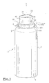
- la figure 1 représente une vue en perspective d'un ensemble de distribution, équipé d'une tête de distribution, selon un premier mode de réalisation de l'invention ;
- la figure 2 illustre, en perspective, une vue de la tête de distribution de la figure 1, en position ouverte ;
- la figure 3 est une vue schématique, en perspective éclatée, de la tête de distribution de la figure 1, représentée en phase d'assemblage ;
- la figure 4 représente une vue de détail en perspective, de la tête de distribution de la figure 3, représentée après assemblage ;
- la figure 5 représente, en coupe axiale, une vue schématique de la tête de distribution représentée sur les figures. 1 à 4 ;
- la figure 6 représente, en coupe axiale, une vue schématique d'une tête de distribution, suivant un autre mode de réalisation de l'invention ;
- la figure 7 représente, en coupe axiale, une vue schématique d'une tête de distribution, suivant encore un autre mode de réalisation de l'invention ; et
- la figure 8 enfin, représente, en perspective, une vue éclatée d'une tête de distribution, suivant encore un autre mode encore de réalisation de l'invention.
- FIG. 1 represents a perspective view of a dispensing assembly, equipped with a dispensing head, according to a first embodiment of the invention;
- FIG. 2 illustrates, in perspective, a view of the dispensing head of FIG. 1, in the open position;
- Figure 3 is a schematic view, in exploded perspective, of the dispensing head of Figure 1, shown in the assembly phase;
- Figure 4 shows a detailed perspective view of the dispensing head of Figure 3, shown after assembly;
- 5 shows, in axial section, a schematic view of the dispensing head shown in the figures. 1 to 4;
- FIG. 6 represents, in axial section, a schematic view of a dispensing head, according to another embodiment of the invention;
- FIG. 7 represents, in axial section, a schematic view of a dispensing head, according to yet another embodiment of the invention; and
- Figure 8 finally shows, in perspective, an exploded view of a dispensing head, according to yet another embodiment of the invention.
En référence, notamment aux figures 1 à 5, on a désigné généralement par la
référence 1 un ensemble de distribution, conforme à un premier mode de
réalisation de l'invention. Comme visible sur les figures 1 et 2, l'ensemble de
distribution 1 comporte un réservoir cylindrique 2, du type bidon métallique, d'axe
X, dans lequel est conditionné un produit liquide, tel qu'une laque capillaire. Le
réservoir 2 est mis sous pression, notamment à l'aide d'un gaz propulseur du type
liquéfiable ou comprimé.With reference, in particular to FIGS. 1 to 5, generally designated by the
reference 1 a distribution assembly, conforming to a first mode of
realization of the invention. As shown in Figures 1 and 2, all of
Le réservoir 2 présente, de façon classique, un corps cylindrique, un fond 4 fermé
et un bord roulé 6, définissant sur sa partie supérieure une ouverture circulaire.
Dans cette ouverture est fixée, par exemple par sertissage ou dudgeonnage, une
coupelle porte-valve 8 (voir figure 2). La coupelle 8 forme dans son centre un
dôme cylindrique 10, dans lequel est monté le corps d'une valve de distribution
12. Le dôme cylindrique 10 est entouré d'une zone annulaire en dépression 11.
Une première extrémité de la valve 12 comporte une tige d'actionnement 14,
émergeant à l'extérieur, et traversant le centre de la coupelle 8, au niveau du
dôme 10. L'axe de la tige d'actionnement 14 est confondu avec l'axe X du
réservoir. A l'intérieur du réservoir 2, la seconde extrémité de la valve se prolonge
par un tube plongeur 16 s'étendant sensiblement jusqu'au fond 4 du récipient. Le
tube plongeur permet d'acheminer le produit, contenu dans le réservoir, vers la
valve 12. La valve utilisée peut être une valve du type à enfoncement, mâle ou
femelle, ou bien une valve actionnable par basculement latéral de la tige de valve
14.The
Sur l'extrémité libre de la tige de valve 14 est montée une tête de distribution 18,
réalisée en deux parties 20, 30. Une première partie 20 forme le corps de la tête
de distribution 18. L'extrémité libre de la tige de valve 14 est engagée dans le
corps. A cet effet, le corps 20 comporte des moyens de raccordement tubulaires
22a destinés à l'emmanchement à force du corps 20 sur la tige de valve 14. La
portion 22a constitue une portion d'extrémité du canal 50. Le canal 50 achemine
le produit depuis la tige de valve vers un orifice de distribution 32, comme ceci
sera détaillé par la suite.A dispensing
Sur le corps 20 est montée, de manière mobile entre une première position ou
position fermée (figures 1, 4 et 5) et une seconde position ou position ouverte
(figure 2), un élément pivotant 30. Dans cet élément pivotant 30 est pratiqué
l'orifice de distribution 32, en communication avec le canal d'amenée 50.
L'élément mobile 30 est rapporté sur le corps 20 et articulé sur celui-ci par une
charnière à goupilles 36a/36b. Un axe de pivot Z est défini par les goupilles 36a.On the
Cependant, il est envisageable de réaliser cette liaison par une charière-film,
permettant de réaliser ainsi le corps 20 et l'élément mobile 30 en une seule pièce.However, it is possible to carry out this connection by a film barrier,
thus making the
L'élément mobile 30 constitue un organe d'ouverture et de fermeture, dont
l'ouverture permet d'accéder aux différentes parties du canal d'amenée 50 de la
tête de distribution 18, ainsi qu'à la face intérieur de l'orifice de distribution 32.The
Par cette configuration, le canal d'amenée 50 est défini en partie, d'une part par le
corps 20, et d'autre part par l'élément mobile 30.By this configuration, the
L'élément mobile 30 a la forme générale d'un élément en « L », présentant une
face frontale 31 sensiblement plane, dont une extrémité inférieure porte
latéralement les goupilles 36a de la charnière. A l'opposé de la charnière, la face
frontale 31 est raccordée à un plateau 37, orienté perpendiculairement à la face
frontale 31. Le plateau 37 se termine par une portion repliée 38 dont l'orientation
est sensiblement parallèle à la face 31.The
La face frontale 31 de l'élément mobile 30 comporte une buse de pulvérisation 34,
de forme générale circulaire. Le centre de la buse 34 est percé, de manière à
former l'orifice de distribution 32. Avantageusement, l'orifice de pulvérisation 32
est un perçage cylindrique, d'un diamètre d'environ 0,15 mm à environ 1 mm.
Avantageusement encore, la profondeur de cet orifice de distribution 32 est
d'environ 0,1 mm à environ 1 mm.The
La buse 34 est reliée au reste de l'élément mobile 30 par des moyens élastiques
40, matérialisés, selon le mode de réalisation considéré, par une zone annulaire
41. Cette zone annulaire 41 peut être réalisée en un matériau élastiquement
étirable. La buse proprement dite, c'est-à-dire la portion 34 dans laquelle est
pratiqué l'orifice de distribution est réalisée, en un matériau sensiblement rigide
ou semi-rigide. La zone annulaire 41 l'entourant, peut être réalisée en un matériau
thermoplastique élastomérique, par exemple par bi-injection sur un matériau non
élastomérique, notamment rigide à semi-rigide, formant le reste de l'élément
mobile 30. Par cette configuration, la buse 34 est en quelque sorte « suspendue »
dans l'élément mobile 30 par la zone annulaire 41, et est déplaçable
élastiquement dans le sens de la normale du plan de la face frontale 31. En
d'autres termes, un déplacement élastique de la buse 34 peut être effectué dans
le sens de la direction de sortie Y du produit au travers de l'orifice de distribution
32.The
Il est bien entendu que, sans sortir du cadre de la présente invention, la zone
annulaire 41 peut être réalisée en un seul matériau avec l'élément mobile 30,
notamment sous la forme d'une membrane de moindre épaisseur. Une telle
membrane annulaire 41 peut former des ondulations concentriques ou un soufflet
(figure 3), favorisant sous contrainte, le déplacement élastique de l'orifice de
distribution 32 selon l'orientation de l'axe Y, par rapport au reste de l'élément
mobile 30. Dans ce mode de réalisation où l'élément mobile 30 est réalisé en un
matériau unique, avantageusement on choisit un matériau semi-rigide tel que le
polyéthylène.It is understood that, without departing from the scope of the present invention, the area
annular 41 can be made of a single material with the
Le corps 20 forme une base 20a définissant un plateau circulaire 20b. Sur le
plateau 20b est disposée une structure cylindrique, comportant un évidement 21
conformé de sorte que l'élément mobile 30 puisse y être logé, lorsque l'élément
mobile 30 est dans la première position ou position fermée. La base 20a est
délimitée par une jupe périphérique 20c, apte à coulisser axialement à l'intérieur
de la coupelle 8, lors de l'actionnement de la valve 12.The
L'évidement 21 comporte une partie frontale 21a destinée à recevoir la partie
frontale 31 de l'élément mobile 30. Il comporte une partie supérieure 21b destinée
à recevoir le plateau 37 de l'élément mobile 30. Il comporte une partie arrière 21c
destinée à recevoir la partie arrière 38 de l'élément mobile 30.The
Ainsi, dans la première position de l'élément mobile 30, la face frontale 31 de
celui-ci se plaque sur la partie frontale 21a de l'évidement. De manière semblable,
le plateau 37 se place sur la surface supérieure 21b de l'évidement 21. La portion
repliée 38 de l'élément mobile 30 se loge sur la face arrière 21c. La portion
repliée 38 constitue ainsi des moyens d'accrochage assurant le verrouillage, de
façon réversible, de l'élément mobile 30 dans la première position. Par ailleurs,
comme on verra par la suite, le plateau 37 constitue une surface d'appui
permettant à l'utilisateur, par pression axiale à l'aide d'un doigt, d'actionner la
valve de distribution 12.Thus, in the first position of the
Alternativement ou de manière supplémentaire, le plateau 37 peut comporter des
moyens de verrouillage supplémentaires 38a/38b, comme illustrés sur la figure 2.
Ces moyens de verrouillage supplémentaires 38a/38b sont constitués ici par des
tétons latéraux 38a de l'élément mobile 30, aptes à coopérer, en position fermée
de l'ensemble, avec des portions creuses complémentaires 38b, prévues sur les
côtés de l'évidement 21. Alternatively or additionally, the
Les moyens de raccordement tubulaires 22a à la tige de valve 14 conduisent le
produit, via la partie 22 du canal d'amenée 50, vers la surface supérieure 21b de
l'évidement 21. A cet endroit, la portion 22 débouche dans une portion de canal
sensiblement radiale 23, se prolongeant par un conduit axial 24 creusé dans la
face frontale 21a de l'évidement 21. A son tour, le conduit 24 débouche sur une
portion annulaire 25 du canal d'amenée. A l'intérieur de la portion annulaire, un
pilier central ou « center-post » 28, fait saillie par rapport à la face frontale 21a de
l'évidement 21. Le « center-post » présente une face avant 28a, au centre de
laquelle est creusée une chambre tourbillonnaire 27 de section transversale
circulaire. Une pluralité de canaux 26 débouchent, de manière tangentielle, sur la
chambre tourbillonnaire 27, eux-mêmes en communication avec la portion
annulaire 25.The tubular connection means 22a to the
La chambre tourbillonnaire 27, ainsi les différentes parties du canal d'amenée 50
sont entièrement fermées, lorsque l'élément mobile 30 est dans la première
position. Dans cette position, l'orifice de distribution 32 est sensiblement en face
du centre de la chambre tourbillonnaire 27. La chambre tourbillonnaire favorise, le
cas échéant, un bon mélange du produit et du gaz propulseur et confère au
produit, lors de sa distribution, un mouvement en spirale, convergeant vers le
centre de la chambre tourbillonnaire 27, en regard de l'orifice de distribution 32. Il
en résulte une accélération du produit lors de son passage par l'orifice de
distribution 32, et ainsi un éclatement du produit en particules sensiblement
homogènes, permettant l'obtention d'un spray de bonne qualité.The
La réalisation d'une telle chambre tourbillonnaire 27 convient, notamment, à la
pulvérisation d'un produit de faible viscosité, mis sous pression dans le réservoir 2
notamment par un gaz propulseur non soluble dans le produit. Le gaz propulseur,
peut être choisi parmi les gaz comprimés (CO2, azote, air comprimé), les gaz
liquéfiés ou leur mélanges.The production of such a
Pour assurer une bonne étanchéité entre, d'une part les différentes portions du
canal d'amenée 50 et respectivement de la chambre tourbillonnaire 27, et d'autre
part l'élément mobile 30, des moyens d'étanchéité 70a, 70b peuvent être prévus. To ensure a good seal between, on the one hand the different portions of the
De tels moyens d'étanchéité peuvent être réalisés sous la forme d'un joint
d'étanchéité 70a, réalisé en un matériau élastique et entourant l'ensemble des
différentes portions du canal d'amenée 50, y compris la chambre tourbillonnaire
27. Le joint d'étanchéité 70a est légèrement proéminent et se comprime lorsque
l'élément mobile passe de la seconde position à la première. Alternativement, le
joint élastique 70a peut être remplacé par un système comportant un bourrelet et
une gorge complémentaire, disposé autour des différentes portions formant le
canal d'amenée. Ainsi, un bourrelet 70a peut être réalisé sur le corps 20, apte à
coopérer avec une gorge complémentaire 70b, prévue sur l'élément mobile 30
(voir figure 3), ou vice versa, lorsque ce dernier est dans la première position.Such sealing means can be produced in the form of a seal.
sealing 70a, made of an elastic material and surrounding all of the
different portions of the
La distribution d'une dose de produit P est effectuée, de manière classique. En
effet, l'actionnement de la valve de distribution 12 peut être effectué par simple
pression sur la surface supérieure 37 de la tête de distribution 18, lorsque la valve
est une valve à enfoncement. Dans le cas d'une valve à basculement latéral,
l'actionnement de la valve est effectué en appuyant latéralement sur la tête de
distribution.The distribution of a dose of product P is carried out, in a conventional manner. In
Indeed, the actuation of the dispensing
Après distribution d'une dose de produit, des- résidus de produit peuvent rester
accrochés dans les canaux d'amenée 50, et notamment dans la chambre
tourbillonnaire 27, en particulier au voisinage de l'orifice de distribution 32. Or
après un repos prolongé, par exemple par évaporation d'un solvant que le produit
contient, ou par oxydation du produit, il se produit la formation de résidus secs,
risquant de boucher entièrement ou partiellement le canal d'amenée et/ou l'orifice
de distribution 32.After dispensing a dose of product, product residues may remain
hung in the
Lorsqu'un tel bouchage de la 50 et/ou de la chambre tourbillonnaire 27 et/ou de
l'orifice de distribution 32 s'impose. A cet effet, l'utilisateur fait pivoter l'élément
mobile 30 autour de l'axe Z, après desencliquetage de la portion d'accrochage 38
et/ou des moyens de verrouillage supplémentaires 38a/38b. Pour assurer une
bonne prise entre les doigts de l'utilisateur, une portion de surface de l'élément
mobile 30 peut comporter un profil anti-dérapant. When such a blockage of the 50 and / or of the
En écartant l'élément mobile 30, par pivotement autour de l'axe Z, du corps 20,
les différentes parties du canal d'amenée 50, la chambre tourbillonnaire 27 et
l'intérieur de la buse 34 deviennent accessibles, et peuvent être nettoyés. Les
deux parties 20, 30 écartées peuvent alors être nettoyées, par exemple par
enlèvement mécanique des résidus, ou par rinçage, notamment à l'eau sous le
robinet.By moving aside the
Après séchage, l'élément mobile 30 est repositionné sur le corps 20 par un
mouvement de pivot dans le sens de la flèche F1 (figure 2), suivant un
mouvement effectué dans le sens inverse au sens d'ouverture. En position
fermée de l'élément mobile 30 sur le corps 20, la paroi interne de la buse 34 se
trouve plaquée, de manière élastique, contre la face avant 28a du « center-post ».
Ainsi, l'orifice de distribution 32 est plaqué en permanence, de manière élastique,
contre la chambre tourbillonnaire 27, par étirement de la membrane élastique 40.
L'appui élastique de la buse 34 sur le corps 20 de la tête de distribution, et plus
précisément sur la face avant 28a du « center-post », est symbolisé sur les
figures 4 et 5 par les flèches F2.After drying, the
II est à noter que, selon l'invention, l'orifice de distribution 32 est, après l'opération
de nettoyage du canal d'amenée ou de la buse, repositionné exactement dans la
position initiale, par rapport à la chambre tourbillonnaire 27, assurant ainsi une
reproductibilité parfaite des qualités de pulvérisation de la tête de distribution 18.It should be noted that, according to the invention, the dispensing
La figure 6 illustre une vue en coupe axiale d'un mode de réalisation d'une tête de
distribution 18', simplifiée par rapport au mode de réalisation décrit
précédemment. En effet, la tête de distribution 18' ne comporte pas de chambre
tourbillonnaire, ni de « center-post ». Ainsi, les différentes portions 22, 23, 24, du
canal d'amenée 50 conduisent le produit directement vers l'orifice de distribution
32. En position fermée de la tête de distribution 18', la face interne 31a de
l'élément mobile 30 est directement en appui élastique, dans le sens des flèches
F2, sur une portion plane 21 a du corps 20. A cet effet, et de la même manière que
pour le mode de réalisation précédent, l'orifice de distribution 32 est ménagé au
centre d'une portion 34 reliée à l'élément mobile via un anneau de matériau
élastiquement étirable 41 dont les caractéristiques, notamment d'étirabilité, sont
choisies de sorte que, en position montée de l'élément mobile 30 sur le corps 20,
la portion 34 soit contrainte élastiquement contre la portion 21a du corps 20.FIG. 6 illustrates a view in axial section of an embodiment of a dispensing
Sur la figure 7 on a représenté une tête de distribution 18", qui diffère par rapport
au mode de réalisation décrit précédemment en référence aux figures 1 à 5 par le
fait que la tête de distribution 18" ne comporte pas de « center-post ». Par rapport
à la tête de distribution 18 (voir notamment à la figure 5), dans laquelle la
chambre tourbillonnaire 27 ainsi que les canaux tangentiels 26 sont creusés dans
une portion solidaire du corps 20, dans la tête de distribution 18", la chambre
tourbillonnaire 27 ainsi que les canaux tangentiels 26 sont creusés dans la buse
34. Ainsi, le corps 20 forme une face frontale plane 21a sur laquelle est plaquée,
de manière élastique, la face interne 34a de la buse 34. Sur cette face interne 34a
sont moulés la chambre tourbillonnaire 27 et les canaux tangentiels 26. En
position fermée de la tête de distribution 18", la face interne 34a est directement
en appui élastique, dans le sens des flèches F2, sur une portion plane 21a du
corps 20. Les canaux tangentiels 26 sont en communication avec un canal
annulaire 25 formé entre la portion plane 21a du corps 20 et la membrane
annulaire 41. Le canal annulaire 25 communique avec la tige de valve via les
portions 22, 23 et 24 du canal d'amenée 50.In FIG. 7, a dispensing
L'utilisation et le nettoyage des têtes de distribution 18' et 18" s'effectue de
manière semblable à l'utilisation et le nettoyage de la tête de distribution 18,
comme décrit précédemment.The use and cleaning of the 18 'and 18 "dispensing heads is carried out
similar to the use and cleaning of the dispensing
Un autre mode de réalisation d'une tête de distribution 118 est représenté sur la
figure 8. La structure de la tête de distribution 118 est sensiblement similaire à la
structure de la tête de distribution 18 du premier mode de réalisation, décrit
précédemment. Les pièces identiques à celles des figures 1 à 5 portent les
mêmes numéros de référence. Seuls les éléments qui diffèrent seront décrits en
détail par la suite. Les numéros de référence de ces éléments portent un numéro
supérieur à 100. Another embodiment of a dispensing
La tête de distribution 118 comporte un corps 120 pourvu d'une face frontale 21a
plane. La face frontale 21a est pourvu d'un canal annulaire 25 entourant un
« center-post » 28 de forme générale cylindrique. La face avant 28a du « center-post
» émerge légèrement du plan de la face frontale 21a. Le « center-post » 28
présente une structure composite. Il présente une base de section circulaire 128b
délimitant radialement la portion intérieure du canal annulaire 25. La base 128b
est venue de matière avec le corps 120 et réalisé en un matériau thermoplastique
relativement rigide. Sur la base 128b est disposée une zone 140 réalisée en un
matériau élastiquement compressible. La zone élastiquement compressible 140
est couverte d'un plateau 128a destiné à venir en appui élastique contre la face
frontale interne 31 de l'élément mobile 130, lorsque ce dernier est en position
verrouillée sur le corps 120. En position de verrouillage de l'élément mobile 130,
la zone élastiquement compressible 140 est comprimée, de sorte que la face
apparente du plateau 128a vienne au contact élastique de l'élément mobile 130 et
se trouve sensiblement au niveau de la face frontale 21a du corps.The dispensing
Sur la face apparente du plateau 128a sont réalisés des profils aptes à définir,
avec l'élément mobile 130, les canaux tangentiels 26 et la chambre tourbillonnaire
27, de sorte que l'orifice de distribution 32 soit centré sur celle-ci.On the visible face of the
La réalisation de la zone élastiquement compressible 140 du « center-post » 28
peut être effectuée par tout moyen approprié, et notamment par injection multiple
d'un matériau élastomérique approprié sur un matériau sensiblement rigide, puis
d' un matériau sensiblement rigide sur la zone élastiquement compressible 140.The realization of the elastically
L'utilisation et le nettoyage de la tête de distribution 118 s'effectue de manière
semblable à l'utilisation et le nettoyage de la tête de distribution 18, et présente
les mêmes avantages.The use and cleaning of the dispensing
Dans la description détaillée qui précède, il a été fait référence à des modes de réalisation particuliers de l'invention. Il est évident que des variantes peuvent y être apportées sans s'écarter de l'esprit de l'invention, telle que revendiquée ci-après.In the foregoing detailed description, reference has been made to modes of particular realization of the invention. It is obvious that variants may exist there. be made without departing from the spirit of the invention, as claimed below.
Claims (18)
Applications Claiming Priority (2)
| Application Number | Priority Date | Filing Date | Title |
|---|---|---|---|
| FR0014717A FR2816523B1 (en) | 2000-11-15 | 2000-11-15 | CLEANABLE DISPENSING HEAD AND DISPENSER THUS EQUIPPED |
| FR0014717 | 2000-11-15 |
Publications (2)
| Publication Number | Publication Date |
|---|---|
| EP1206972A1 true EP1206972A1 (en) | 2002-05-22 |
| EP1206972B1 EP1206972B1 (en) | 2003-08-13 |
Family
ID=8856486
Family Applications (1)
| Application Number | Title | Priority Date | Filing Date |
|---|---|---|---|
| EP20010402792 Expired - Lifetime EP1206972B1 (en) | 2000-11-15 | 2001-10-26 | Cleanable dispensing head and dispenser equipped therewith |
Country Status (8)
| Country | Link |
|---|---|
| US (1) | US20020060255A1 (en) |
| EP (1) | EP1206972B1 (en) |
| JP (1) | JP2002255264A (en) |
| AT (1) | ATE246961T1 (en) |
| CA (1) | CA2363285A1 (en) |
| DE (1) | DE60100592T2 (en) |
| ES (1) | ES2204815T3 (en) |
| FR (1) | FR2816523B1 (en) |
Cited By (4)
| Publication number | Priority date | Publication date | Assignee | Title |
|---|---|---|---|---|
| WO2005018820A1 (en) * | 2003-08-04 | 2005-03-03 | Valois Sas | Spray head for fluid product |
| EP1647501A1 (en) * | 2004-10-18 | 2006-04-19 | L'oreal | Dispensing device for cosmetic products |
| US7527173B2 (en) | 2004-10-18 | 2009-05-05 | L'oreal | Dispensing device for a cosmetic product |
| EP3246269A1 (en) * | 2016-05-18 | 2017-11-22 | Bertoldi, Massimiliano | Aerosol spray product dispensing device, method of manufacturing such a device and assembling system thereof |
Families Citing this family (25)
| Publication number | Priority date | Publication date | Assignee | Title |
|---|---|---|---|---|
| GB0130057D0 (en) * | 2001-12-14 | 2002-02-06 | Dunne Stephen T | Liquid atomising system |
| US6752296B1 (en) | 2003-03-10 | 2004-06-22 | Saint-Gobain Calmar Inc. | Bi-injection trigger sprayer nozzle cap |
| DE10343672A1 (en) * | 2003-09-18 | 2005-05-04 | Boehringer Ingelheim Micropart | Spray head for an aerosol container |
| DE102005024612A1 (en) * | 2005-05-25 | 2006-11-30 | Wella Ag | Spray head with a nozzle insert |
| NL1029746C2 (en) * | 2005-08-16 | 2007-02-19 | Plasticum Group B V | Spray nozzle. |
| MX2008011252A (en) * | 2006-03-07 | 2008-09-10 | Boehringer Ingelheim Int | Swirl. |
| EP2077132A1 (en) | 2008-01-02 | 2009-07-08 | Boehringer Ingelheim Pharma GmbH & Co. KG | Dispensing device, storage device and method for dispensing a formulation |
| EP2189226B1 (en) * | 2008-11-19 | 2013-09-11 | J. Wagner GmbH | Air cap with separate formed air horn and his manufacturing process with injection mould |
| US10011906B2 (en) | 2009-03-31 | 2018-07-03 | Beohringer Ingelheim International Gmbh | Method for coating a surface of a component |
| EP3508239B1 (en) | 2009-05-18 | 2020-12-23 | Boehringer Ingelheim International GmbH | Adapter, inhalant apparatus and atomizer |
| WO2011064163A1 (en) | 2009-11-25 | 2011-06-03 | Boehringer Ingelheim International Gmbh | Nebulizer |
| UA107097C2 (en) | 2009-11-25 | 2014-11-25 | Бьорінгер Інгельхайм Інтернаціональ Гмбх | Dispenser |
| US10016568B2 (en) | 2009-11-25 | 2018-07-10 | Boehringer Ingelheim International Gmbh | Nebulizer |
| EP2585151B1 (en) | 2010-06-24 | 2018-04-04 | Boehringer Ingelheim International GmbH | Nebulizer |
| WO2012130757A1 (en) | 2011-04-01 | 2012-10-04 | Boehringer Ingelheim International Gmbh | Medical device comprising a container |
| US9827384B2 (en) | 2011-05-23 | 2017-11-28 | Boehringer Ingelheim International Gmbh | Nebulizer |
| WO2013152894A1 (en) | 2012-04-13 | 2013-10-17 | Boehringer Ingelheim International Gmbh | Atomiser with coding means |
| ES2836977T3 (en) | 2013-08-09 | 2021-06-28 | Boehringer Ingelheim Int | Nebulizer |
| WO2015018904A1 (en) | 2013-08-09 | 2015-02-12 | Boehringer Ingelheim International Gmbh | Nebulizer |
| US10195374B2 (en) | 2014-05-07 | 2019-02-05 | Boehringer Ingelheim International Gmbh | Container, nebulizer and use |
| WO2015169430A1 (en) | 2014-05-07 | 2015-11-12 | Boehringer Ingelheim International Gmbh | Nebulizer |
| KR102492824B1 (en) | 2014-05-07 | 2023-01-30 | 베링거 인겔하임 인터내셔날 게엠베하 | Nebulizer, indicator device and container |
| CN105175806B (en) * | 2015-09-10 | 2019-01-11 | 朱志航 | A kind of vehicle high temperature resistant anti-aging rubber sealing strip material and preparation method thereof |
| WO2018208884A1 (en) * | 2017-05-09 | 2018-11-15 | Kyle Rood | Sprayable maple syrup dispenser |
| JP7072988B2 (en) * | 2018-05-31 | 2022-05-23 | 株式会社吉野工業所 | Discharger for aerosol container |
Citations (6)
| Publication number | Priority date | Publication date | Assignee | Title |
|---|---|---|---|---|
| US4253609A (en) * | 1979-01-30 | 1981-03-03 | Essex Chemical Corporation | Dispensing spray nozzle |
| FR2698854A1 (en) | 1992-12-04 | 1994-06-10 | Oreal | Spray push button nozzle for distributor of liq. - contains spray nozzle having spray orifice connected to supply channel from container, with cylindrical surface limiting this orifice having circular section |
| EP0726096A2 (en) | 1995-02-07 | 1996-08-14 | Calmar Inc. | Improvements in or relating to pump sprayers |
| WO1997031841A1 (en) * | 1996-02-28 | 1997-09-04 | Incro Limited | Spraying apparatus and nozzle devices |
| US5803371A (en) * | 1994-07-29 | 1998-09-08 | Toyota Jidosha Kabushiki Kaisha | Injection nozzle |
| FR2787731A1 (en) | 1998-12-29 | 2000-06-30 | Oreal | REMOVABLE DISTRIBUTION HEAD |
Family Cites Families (3)
| Publication number | Priority date | Publication date | Assignee | Title |
|---|---|---|---|---|
| DE3066837D1 (en) * | 1979-08-16 | 1984-04-12 | Canyon Corp | Foam dispenser |
| US5213269A (en) * | 1991-09-13 | 1993-05-25 | Bowles Fluidics Corporation | Low cost, low pressure, feedback passage-free fluidic oscillator with interconnect |
| US5702058A (en) * | 1994-12-01 | 1997-12-30 | Calmar Inc. | Dual foamer nozzle assembly for trigger sprayer |
-
2000
- 2000-11-15 FR FR0014717A patent/FR2816523B1/en not_active Expired - Fee Related
-
2001
- 2001-10-26 EP EP20010402792 patent/EP1206972B1/en not_active Expired - Lifetime
- 2001-10-26 ES ES01402792T patent/ES2204815T3/en not_active Expired - Lifetime
- 2001-10-26 AT AT01402792T patent/ATE246961T1/en not_active IP Right Cessation
- 2001-10-26 DE DE2001600592 patent/DE60100592T2/en not_active Expired - Fee Related
- 2001-11-14 CA CA 2363285 patent/CA2363285A1/en not_active Abandoned
- 2001-11-15 US US09/987,515 patent/US20020060255A1/en not_active Abandoned
- 2001-11-15 JP JP2001350322A patent/JP2002255264A/en not_active Withdrawn
Patent Citations (7)
| Publication number | Priority date | Publication date | Assignee | Title |
|---|---|---|---|---|
| US4253609A (en) * | 1979-01-30 | 1981-03-03 | Essex Chemical Corporation | Dispensing spray nozzle |
| FR2698854A1 (en) | 1992-12-04 | 1994-06-10 | Oreal | Spray push button nozzle for distributor of liq. - contains spray nozzle having spray orifice connected to supply channel from container, with cylindrical surface limiting this orifice having circular section |
| US5803371A (en) * | 1994-07-29 | 1998-09-08 | Toyota Jidosha Kabushiki Kaisha | Injection nozzle |
| EP0726096A2 (en) | 1995-02-07 | 1996-08-14 | Calmar Inc. | Improvements in or relating to pump sprayers |
| WO1997031841A1 (en) * | 1996-02-28 | 1997-09-04 | Incro Limited | Spraying apparatus and nozzle devices |
| FR2787731A1 (en) | 1998-12-29 | 2000-06-30 | Oreal | REMOVABLE DISTRIBUTION HEAD |
| EP1016464A1 (en) * | 1998-12-29 | 2000-07-05 | L'oreal | Disassemblable dispensing head |
Cited By (8)
| Publication number | Priority date | Publication date | Assignee | Title |
|---|---|---|---|---|
| WO2005018820A1 (en) * | 2003-08-04 | 2005-03-03 | Valois Sas | Spray head for fluid product |
| CN100427216C (en) * | 2003-08-04 | 2008-10-22 | 瓦卢瓦有限合伙公司 | Spray head for fluid product |
| US8323020B2 (en) | 2003-08-04 | 2012-12-04 | Aptar France Sas | Machine for manufacturing a spray head |
| US8769818B2 (en) | 2003-08-04 | 2014-07-08 | Aptar France Sas | Spray head for fluid product |
| EP1647501A1 (en) * | 2004-10-18 | 2006-04-19 | L'oreal | Dispensing device for cosmetic products |
| FR2876677A1 (en) * | 2004-10-18 | 2006-04-21 | Oreal | DEVICE FOR DISTRIBUTING A COSMETIC PRODUCT |
| US7527173B2 (en) | 2004-10-18 | 2009-05-05 | L'oreal | Dispensing device for a cosmetic product |
| EP3246269A1 (en) * | 2016-05-18 | 2017-11-22 | Bertoldi, Massimiliano | Aerosol spray product dispensing device, method of manufacturing such a device and assembling system thereof |
Also Published As
| Publication number | Publication date |
|---|---|
| ES2204815T3 (en) | 2004-05-01 |
| ATE246961T1 (en) | 2003-08-15 |
| JP2002255264A (en) | 2002-09-11 |
| FR2816523A1 (en) | 2002-05-17 |
| US20020060255A1 (en) | 2002-05-23 |
| EP1206972B1 (en) | 2003-08-13 |
| DE60100592T2 (en) | 2004-06-24 |
| FR2816523B1 (en) | 2003-01-10 |
| CA2363285A1 (en) | 2002-05-15 |
| DE60100592D1 (en) | 2003-09-18 |
Similar Documents
| Publication | Publication Date | Title |
|---|---|---|
| EP1206972B1 (en) | Cleanable dispensing head and dispenser equipped therewith | |
| EP1048590B1 (en) | Valve actuating device and assembly comprising such a device | |
| CA2159575C (en) | Dispensing valve and dispensing container equipped with such valve | |
| EP0888823B1 (en) | Dispenser for liquid or pasty material comprising pumping means | |
| EP0410857B1 (en) | Assembly for dispensing at least one product, especially cosmetics, in cream, fluid or powder form | |
| CA2248232C (en) | Dispenser head with improved air intake, and packaging and distribution assembly fitted with such a head | |
| EP1016464A1 (en) | Disassemblable dispensing head | |
| EP1035038B1 (en) | Unit for storing and dispensing a product under pressure, especially cosmetics | |
| FR2804666A1 (en) | DISPENSER FOR STORING AT LEAST TWO COMPONENTS AND SELECTIVE DISTRIBUTION OF SINGLE COMPONENT OR MIXTURE THEREOF AND PROCESS FOR IMPLEMENTING THE SAME | |
| EP0939039B1 (en) | Dispensing head for the dispensing of a material and assembly for dispensing under pressure equipped with such a head | |
| FR2884157A1 (en) | HEAD OF DISTRIBUTION | |
| EP0960829B1 (en) | Valve and storing and distribution assembly comprising such a valve | |
| EP0850851B1 (en) | Dispensing valve for pressurised fluids | |
| EP0658490B1 (en) | Depressible valve for vaporising a liquid and pressurised container provided with such a valve | |
| FR2809713A1 (en) | CLEANABLE DISPENSING HEAD AND DISPENSER THUS EQUIPPED | |
| EP0605275A1 (en) | Assembly for spraying a liquid comprising a precompression pump | |
| FR2862623A1 (en) | Tilting type valve for distributing e.g. hair spray, has stem that is displaced from closing position to two opening positions, such that product is distributed under pressure as per respective flows through two orifices | |
| EP1400465A1 (en) | Variable-delivery tiilt valve as well as container having such valve | |
| EP0751083A1 (en) | Aerosol spray valve and aerosol container provided with such a valve | |
| CA2297765C (en) | Valve for pressurised fluid device | |
| EP0764593B1 (en) | Valve for sprayer | |
| FR2814726A1 (en) | Pressurized container spray, useful for dispensing gel, mousse, a cosmetic or a pharmaceutical product, has cap with shutter covering valve outlet until depressed | |
| FR2736332A1 (en) | Sprayer side valve fixed to liquid container neck by skirt - has housing into which liquid and gas propellant supply orifices discharge, orifices being set back from each other in valve sliding direction | |
| FR2841538A1 (en) | PACKAGING AND DISPENSING ASSEMBLY OF A PRODUCT |
Legal Events
| Date | Code | Title | Description |
|---|---|---|---|
| PUAI | Public reference made under article 153(3) epc to a published international application that has entered the european phase |
Free format text: ORIGINAL CODE: 0009012 |
|
| AX | Request for extension of the european patent |
Free format text: AL;LT;LV;MK;RO;SI |
|
| 17P | Request for examination filed |
Effective date: 20021122 |
|
| AKX | Designation fees paid |
Designated state(s): AT BE CH CY DE DK ES FI FR GB GR IE IT LI LU MC NL PT SE TR |
|
| GRAH | Despatch of communication of intention to grant a patent |
Free format text: ORIGINAL CODE: EPIDOS IGRA |
|
| GRAH | Despatch of communication of intention to grant a patent |
Free format text: ORIGINAL CODE: EPIDOS IGRA |
|
| GRAA | (expected) grant |
Free format text: ORIGINAL CODE: 0009210 |
|
| AK | Designated contracting states |
Designated state(s): AT BE CH CY DE DK ES FI FR GB GR IE IT LI LU MC NL PT SE TR |
|
| PG25 | Lapsed in a contracting state [announced via postgrant information from national office to epo] |
Ref country code: TR Free format text: LAPSE BECAUSE OF FAILURE TO SUBMIT A TRANSLATION OF THE DESCRIPTION OR TO PAY THE FEE WITHIN THE PRESCRIBED TIME-LIMIT Effective date: 20030813 Ref country code: NL Free format text: LAPSE BECAUSE OF FAILURE TO SUBMIT A TRANSLATION OF THE DESCRIPTION OR TO PAY THE FEE WITHIN THE PRESCRIBED TIME-LIMIT Effective date: 20030813 Ref country code: IE Free format text: LAPSE BECAUSE OF FAILURE TO SUBMIT A TRANSLATION OF THE DESCRIPTION OR TO PAY THE FEE WITHIN THE PRESCRIBED TIME-LIMIT Effective date: 20030813 Ref country code: FI Free format text: LAPSE BECAUSE OF FAILURE TO SUBMIT A TRANSLATION OF THE DESCRIPTION OR TO PAY THE FEE WITHIN THE PRESCRIBED TIME-LIMIT Effective date: 20030813 Ref country code: AT Free format text: LAPSE BECAUSE OF FAILURE TO SUBMIT A TRANSLATION OF THE DESCRIPTION OR TO PAY THE FEE WITHIN THE PRESCRIBED TIME-LIMIT Effective date: 20030813 |
|
| REG | Reference to a national code |
Ref country code: GB Ref legal event code: FG4D Free format text: NOT ENGLISH |
|
| REG | Reference to a national code |
Ref country code: CH Ref legal event code: EP |
|
| REG | Reference to a national code |
Ref country code: IE Ref legal event code: FG4D Free format text: FRENCH |
|
| REF | Corresponds to: |
Ref document number: 60100592 Country of ref document: DE Date of ref document: 20030918 Kind code of ref document: P |
|
| PGFP | Annual fee paid to national office [announced via postgrant information from national office to epo] |
Ref country code: FR Payment date: 20031003 Year of fee payment: 3 |
|
| PG25 | Lapsed in a contracting state [announced via postgrant information from national office to epo] |
Ref country code: LU Free format text: LAPSE BECAUSE OF NON-PAYMENT OF DUE FEES Effective date: 20031026 Ref country code: CY Free format text: LAPSE BECAUSE OF FAILURE TO SUBMIT A TRANSLATION OF THE DESCRIPTION OR TO PAY THE FEE WITHIN THE PRESCRIBED TIME-LIMIT Effective date: 20031026 |
|
| PG25 | Lapsed in a contracting state [announced via postgrant information from national office to epo] |
Ref country code: MC Free format text: LAPSE BECAUSE OF NON-PAYMENT OF DUE FEES Effective date: 20031031 Ref country code: BE Free format text: LAPSE BECAUSE OF NON-PAYMENT OF DUE FEES Effective date: 20031031 |
|
| PGFP | Annual fee paid to national office [announced via postgrant information from national office to epo] |
Ref country code: DE Payment date: 20031106 Year of fee payment: 3 |
|
| PG25 | Lapsed in a contracting state [announced via postgrant information from national office to epo] |
Ref country code: SE Free format text: LAPSE BECAUSE OF FAILURE TO SUBMIT A TRANSLATION OF THE DESCRIPTION OR TO PAY THE FEE WITHIN THE PRESCRIBED TIME-LIMIT Effective date: 20031113 Ref country code: GR Free format text: LAPSE BECAUSE OF FAILURE TO SUBMIT A TRANSLATION OF THE DESCRIPTION OR TO PAY THE FEE WITHIN THE PRESCRIBED TIME-LIMIT Effective date: 20031113 Ref country code: DK Free format text: LAPSE BECAUSE OF FAILURE TO SUBMIT A TRANSLATION OF THE DESCRIPTION OR TO PAY THE FEE WITHIN THE PRESCRIBED TIME-LIMIT Effective date: 20031113 |
|
| PGFP | Annual fee paid to national office [announced via postgrant information from national office to epo] |
Ref country code: ES Payment date: 20031128 Year of fee payment: 3 |
|
| GBT | Gb: translation of ep patent filed (gb section 77(6)(a)/1977) | ||
| PG25 | Lapsed in a contracting state [announced via postgrant information from national office to epo] |
Ref country code: PT Free format text: LAPSE BECAUSE OF FAILURE TO SUBMIT A TRANSLATION OF THE DESCRIPTION OR TO PAY THE FEE WITHIN THE PRESCRIBED TIME-LIMIT Effective date: 20040113 |
|
| NLV1 | Nl: lapsed or annulled due to failure to fulfill the requirements of art. 29p and 29m of the patents act | ||
| REG | Reference to a national code |
Ref country code: IE Ref legal event code: FD4D |
|
| BERE | Be: lapsed |
Owner name: L'*OREAL Effective date: 20031031 |
|
| REG | Reference to a national code |
Ref country code: ES Ref legal event code: FG2A Ref document number: 2204815 Country of ref document: ES Kind code of ref document: T3 |
|
| PLBE | No opposition filed within time limit |
Free format text: ORIGINAL CODE: 0009261 |
|
| STAA | Information on the status of an ep patent application or granted ep patent |
Free format text: STATUS: NO OPPOSITION FILED WITHIN TIME LIMIT |
|
| 26N | No opposition filed |
Effective date: 20040514 |
|
| PG25 | Lapsed in a contracting state [announced via postgrant information from national office to epo] |
Ref country code: ES Free format text: LAPSE BECAUSE OF NON-PAYMENT OF DUE FEES Effective date: 20041027 |
|
| PG25 | Lapsed in a contracting state [announced via postgrant information from national office to epo] |
Ref country code: DE Free format text: LAPSE BECAUSE OF NON-PAYMENT OF DUE FEES Effective date: 20050503 |
|
| PG25 | Lapsed in a contracting state [announced via postgrant information from national office to epo] |
Ref country code: FR Free format text: LAPSE BECAUSE OF NON-PAYMENT OF DUE FEES Effective date: 20050630 |
|
| REG | Reference to a national code |
Ref country code: FR Ref legal event code: ST |
|
| PG25 | Lapsed in a contracting state [announced via postgrant information from national office to epo] |
Ref country code: IT Free format text: LAPSE BECAUSE OF NON-PAYMENT OF DUE FEES Effective date: 20051026 Ref country code: GB Free format text: LAPSE BECAUSE OF NON-PAYMENT OF DUE FEES Effective date: 20051026 |
|
| PG25 | Lapsed in a contracting state [announced via postgrant information from national office to epo] |
Ref country code: LI Free format text: LAPSE BECAUSE OF NON-PAYMENT OF DUE FEES Effective date: 20051031 Ref country code: CH Free format text: LAPSE BECAUSE OF NON-PAYMENT OF DUE FEES Effective date: 20051031 |
|
| REG | Reference to a national code |
Ref country code: ES Ref legal event code: FD2A Effective date: 20041027 |
|
| REG | Reference to a national code |
Ref country code: CH Ref legal event code: PL |
|
| GBPC | Gb: european patent ceased through non-payment of renewal fee |
Effective date: 20051026 |