EP1206972A1 - Reinigbarer Ausgabekopf und damit ausgerüsteter Ausgeber - Google Patents
Reinigbarer Ausgabekopf und damit ausgerüsteter Ausgeber Download PDFInfo
- Publication number
- EP1206972A1 EP1206972A1 EP20010402792 EP01402792A EP1206972A1 EP 1206972 A1 EP1206972 A1 EP 1206972A1 EP 20010402792 EP20010402792 EP 20010402792 EP 01402792 A EP01402792 A EP 01402792A EP 1206972 A1 EP1206972 A1 EP 1206972A1
- Authority
- EP
- European Patent Office
- Prior art keywords
- dispensing
- dispensing head
- head according
- orifice
- product
- Prior art date
- Legal status (The legal status is an assumption and is not a legal conclusion. Google has not performed a legal analysis and makes no representation as to the accuracy of the status listed.)
- Granted
Links
Images


Classifications
-
- B—PERFORMING OPERATIONS; TRANSPORTING
- B65—CONVEYING; PACKING; STORING; HANDLING THIN OR FILAMENTARY MATERIAL
- B65D—CONTAINERS FOR STORAGE OR TRANSPORT OF ARTICLES OR MATERIALS, e.g. BAGS, BARRELS, BOTTLES, BOXES, CANS, CARTONS, CRATES, DRUMS, JARS, TANKS, HOPPERS, FORWARDING CONTAINERS; ACCESSORIES, CLOSURES, OR FITTINGS THEREFOR; PACKAGING ELEMENTS; PACKAGES
- B65D83/00—Containers or packages with special means for dispensing contents
- B65D83/14—Containers or packages with special means for dispensing contents for delivery of liquid or semi-liquid contents by internal gaseous pressure, i.e. aerosol containers comprising propellant for a product delivered by a propellant
- B65D83/34—Cleaning or preventing clogging of the discharge passage
- B65D83/345—Anti-clogging means for outlets
-
- B—PERFORMING OPERATIONS; TRANSPORTING
- B05—SPRAYING OR ATOMISING IN GENERAL; APPLYING FLUENT MATERIALS TO SURFACES, IN GENERAL
- B05B—SPRAYING APPARATUS; ATOMISING APPARATUS; NOZZLES
- B05B1/00—Nozzles, spray heads or other outlets, with or without auxiliary devices such as valves, heating means
- B05B1/34—Nozzles, spray heads or other outlets, with or without auxiliary devices such as valves, heating means designed to influence the nature of flow of the liquid or other fluent material, e.g. to produce swirl
- B05B1/3405—Nozzles, spray heads or other outlets, with or without auxiliary devices such as valves, heating means designed to influence the nature of flow of the liquid or other fluent material, e.g. to produce swirl to produce swirl
- B05B1/341—Nozzles, spray heads or other outlets, with or without auxiliary devices such as valves, heating means designed to influence the nature of flow of the liquid or other fluent material, e.g. to produce swirl to produce swirl before discharging the liquid or other fluent material, e.g. in a swirl chamber upstream the spray outlet
- B05B1/3421—Nozzles, spray heads or other outlets, with or without auxiliary devices such as valves, heating means designed to influence the nature of flow of the liquid or other fluent material, e.g. to produce swirl to produce swirl before discharging the liquid or other fluent material, e.g. in a swirl chamber upstream the spray outlet with channels emerging substantially tangentially in the swirl chamber
- B05B1/3431—Nozzles, spray heads or other outlets, with or without auxiliary devices such as valves, heating means designed to influence the nature of flow of the liquid or other fluent material, e.g. to produce swirl to produce swirl before discharging the liquid or other fluent material, e.g. in a swirl chamber upstream the spray outlet with channels emerging substantially tangentially in the swirl chamber the channels being formed at the interface of cooperating elements, e.g. by means of grooves
- B05B1/3436—Nozzles, spray heads or other outlets, with or without auxiliary devices such as valves, heating means designed to influence the nature of flow of the liquid or other fluent material, e.g. to produce swirl to produce swirl before discharging the liquid or other fluent material, e.g. in a swirl chamber upstream the spray outlet with channels emerging substantially tangentially in the swirl chamber the channels being formed at the interface of cooperating elements, e.g. by means of grooves the interface being a plane perpendicular to the outlet axis
-
- B—PERFORMING OPERATIONS; TRANSPORTING
- B05—SPRAYING OR ATOMISING IN GENERAL; APPLYING FLUENT MATERIALS TO SURFACES, IN GENERAL
- B05B—SPRAYING APPARATUS; ATOMISING APPARATUS; NOZZLES
- B05B11/00—Single-unit hand-held apparatus in which flow of contents is produced by the muscular force of the operator at the moment of use
- B05B11/0005—Components or details
-
- B—PERFORMING OPERATIONS; TRANSPORTING
- B65—CONVEYING; PACKING; STORING; HANDLING THIN OR FILAMENTARY MATERIAL
- B65D—CONTAINERS FOR STORAGE OR TRANSPORT OF ARTICLES OR MATERIALS, e.g. BAGS, BARRELS, BOTTLES, BOXES, CANS, CARTONS, CRATES, DRUMS, JARS, TANKS, HOPPERS, FORWARDING CONTAINERS; ACCESSORIES, CLOSURES, OR FITTINGS THEREFOR; PACKAGING ELEMENTS; PACKAGES
- B65D83/00—Containers or packages with special means for dispensing contents
- B65D83/14—Containers or packages with special means for dispensing contents for delivery of liquid or semi-liquid contents by internal gaseous pressure, i.e. aerosol containers comprising propellant for a product delivered by a propellant
- B65D83/28—Nozzles, nozzle fittings or accessories specially adapted therefor
Definitions
- the present invention relates to a dispensing head intended to equip a dispenser for a fluid product to be dispensed in the form of a jet or a spray, as well as a distributor provided with such a distribution head. More in particular, the invention relates to a dispensing head comprising means facilitating cleaning, in the event of blockage.
- a fluid distributor as targeted by the present invention, includes a reservoir containing the product to be dispensed, provided with one end open, on which is fixed a distribution member.
- a distribution member Such an organ of distribution can be a pump or a valve, surmounted by a distribution.
- a distribution head of this type must ensure in particular two functions. On the one hand, it must allow the user to order actuation of the dispensing member, to eject a dose of product outside of the tank. On the other hand, it must allow the product leaving the tank to a dispensing orifice.
- a dispensing orifice is in particular in the form of a nozzle, connected to the dispensing member via a supply duct with which the distribution head is provided.
- the distribution of product is then produced in the form of a more or less filiform jet, or the shape of a cloud of fine droplets, called a spray.
- the routing of product to the dispensing orifice can also be carried out by simple pressure on a compressible product tank.
- the distributor is equipped with a distribution valve, in addition to the product, the tank contains a gas under pressure to propel the product to be dispensed through the orifice of distribution.
- a distribution head for the distribution of a product liquid comprises a body provided with a supply conduit in communication with the product reservoir, this conduit opening onto a dispensing nozzle provided an outlet, of small section.
- a nozzle is a insert, fixed, during manufacture, on the dispensing head, so not removable.
- Such a clogging phenomenon can occur quite frequently, when the product is a solution or dispersion that dries easily in the open air.
- a dispensing head intended to equip a fluid dispenser under the form of a jet or spray, comprising: - a body provided with a supply duct in communication with a pump or valve stem of the distributor, and - a part mounted on said body, said part comprising a dispensing orifice can be removably placed in communication with the conduit inlet, said part being movable at will, relative to said body, in view cleaning the supply duct.
- document EP-A-0 726 096 describes a spray head in which the dispensing orifice is movable relative to a supply duct of product, ending in an annular vortex chamber leading to said dispensing orifice.
- the mobility of the dispensing orifice aims to make vary the divergence characteristics of the spray obtained. Access to this vortex chamber and / or supply ducts, for cleaning these last, is not possible.
- the invention relates to a dispensing head whose structure allows the assembly or reassembly of the nozzle relative to the conduit respectively supply, with a precise and reproducible adjustment, as well as with a reliable sealing.
- the invention relates to an improvement of a cleanable dispensing head, capable of ensuring, throughout its period of use, the production of a jet or a spray, in fine droplets of constant quality.
- the elastic support between the body and the element mobile carrying the dispensing orifice allows, after dismantling and cleaning the supply channel, to reposition it precisely in its initial position, by with respect to the terminal portion of the intake channel, thus ensuring perfect reproducibility of the distribution qualities, or even the qualities of spraying, from the dispensing head.
- the elastic means are arranged to so that they exert a restoring force, parallel to an axis of exit of the product (passing through the dispensing orifice).
- the dispensing orifice is formed in a nozzle spraying, integral, in particular with the mobile element.
- the inlet channel delimits, in cooperation with the movable element, when the latter is in the first position, a vortex chamber in communication with the dispensing orifice.
- the rest of the intake channel can be partially delimited by the movable element and, in part by the body.
- the vortex chamber is provided with a central pillar, commonly called “center-post”, delimiting in cooperation with the element mobile, when the latter is in the first position, said chamber vortex.
- a central pillar commonly called “center-post”
- Such a “center-post” generally cylindrical in shape, thus that such a vortex chamber are described, for example, in the document FR-A-2 698 854.
- a vortex chamber is a recess, located directly upstream of the distribution orifice and supplied by a plurality of conduits, forming part of the inlet channel, and opening tangentially into the whirlpool room.
- This vortex chamber, as well as the tangential conduits can be hollowed out on the body, and more precisely on a front face of the "center-post".
- the vortex chamber, as well as the tangential channels can be engraved on the mobile element, more precisely on its internal face, intended to come into contact with the body.
- Such a vortex chamber is able to impart to the product flow, just before crossing the dispensing orifice, a spiral acceleration movement convergent, which makes it possible to obtain a burst in droplets particularly fine product, after passing through said dispensing orifice.
- This effect is particularly useful, especially when using a precompression, or a distribution valve in combination with a gas compressed propellant, not soluble in the product.
- the valve can be an additional gas valve, well known in the art.
- the "center-post" is projecting from a surface of the body, located opposite the orifice of distribution.
- the elastic means can be integral with the movable element.
- the elastic means can advantageously consist of an elastically stretchable membrane, arranged, advantageously at a distance, all around the dispensing orifice, in particular in the form of an annular element.
- the elasticity of the membrane is such that when the movable member is in the first position, a portion of the movable element located inside of the ring delimited by the membrane and in which the orifice of the distribution, is in elastic support on the "center-post".
- the elastic means can be in solidarity with the body, and in particular be part of the “center-post”.
- the "Center-post” may be, at least in part, elastically compressible in a direction parallel to the product exit axis.
- the elastic means can advantageously be formed of an elastomeric material, chosen in particular in the group of thermoplastic polyester-urethane (AU) elastomers, polybutadiene (BR), bromobutyl (BIIR) or chlorobutyl (CIIR) rubbers, chlorinated polyethylene (CM), polyester-aramid copolymers (CPA), polyester-glycol (CPE), polychloroprene (CR), polyethylene copolymers chlorosulfonated (CSM), copolymers of ethylene and methyl acrylate (EAM), terpolymers of ethylene, propylene and a diene (EPDM), copolymers of ethylene and propylene (EPM), polyether-urethanes (EU), fluorocarbon co- or terpolymers (FKM, FPM), butyl rubber (IIR), polyisoprene (IR, NR), nitrile rubber (NBR), polyurethanes (PUR),
- AU thermoplastic polyester
- the dispensing head can be produced by bi-injection (or over-molding) of a thermoplastic elastomer forming the means elastic, and a non-elastomeric material, forming the rest of the head distribution.
- thermoplastic material is chosen, by example of polyethylene (LDPE / HDPE), styrene-butadiene block copolymers (SBS), propylene-ethylene copolymers (PP / PE), polypropylene (PP) or polyamides (PA), making it possible to make the means elastic in the form of a zone, in particular annular, of lesser thickness inside which the dispensing orifice is made, this zone of least thickness being able to deform elastically in a direction parallel to the axis of output of the product, when the movable element passes from the second to the first position.
- LDPE / HDPE polyethylene
- SBS styrene-butadiene block copolymers
- PP / PE propylene-ethylene copolymers
- PP polypropylene
- PA polyamides
- Sealing means may also be provided, so as to ensure a suitable seal between the body and the movable element, when the latter is in the first position.
- Such sealing means can be produced in the form of a system with bead / groove, arranged in particular, continuously, around the parts forming the supply channel.
- a bead can be produced on the body, suitable to cooperate with a complementary groove of the movable element, or vice versa, when the latter is in the first position.
- the sealing means can be produced in the form of a elastically compressible cord, similarly arranged around the parts forming the supply channel. This cord can be made alternately on the body or on the movable element, slightly prominently.
- the passage from the first position to the second of the movable element, and vice versa is made by a pivoting movement of the element movable around an axis perpendicular to the product exit axis.
- the mobile element can be articulated on said body using a hinge, in particular a film hinge or a pin hinge.
- hooking / locking means can be provided for reversibly locking the movable element in the first position.
- the invention also relates to an assembly for packaging and distribution of a product, in particular a cosmetic product, said assembly being surmounted a distribution element, in particular a pump or a valve, equipped a distribution head as defined above.
- this set includes a dispensing valve
- the product to be dispensed is advantageously conveyed to the valve by means of a propellant under pressure, acting directly or indirectly on the product contained in a reservoir, in communication with said valve, which is provided with the assembly.
- the dispensing head of the invention is shaped as a push button having a bearing surface, on which the user presses to cause the ejection of a dose of product.
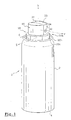
- distribution 1 comprises a cylindrical tank 2, of the metal canister type, with an axis X, in which a liquid product is conditioned, such as a hair spray.
- the tank 2 is pressurized, in particular using a propellant of the type liquefiable or compressed.
- the reservoir 2 has, in a conventional manner, a cylindrical body, a closed bottom 4 and a rolled edge 6, defining on its upper part a circular opening.
- a valve holder cup 8 (see figure 2).
- the cup 8 forms in its center a cylindrical dome 10, in which the body of a distribution valve is mounted 12.
- the cylindrical dome 10 is surrounded by an annular zone in depression 11.
- a first end of the valve 12 comprises an actuating rod 14, emerging outside, and passing through the center of the cup 8, at the dome 10.
- the axis of the actuating rod 14 coincides with the axis X of the tank.
- the second end of the valve extends by a dip tube 16 extending substantially to the bottom 4 of the container.
- the dip tube allows the product contained in the tank to be conveyed to the valve 12.
- the valve used can be a push-in type valve, male or female, or a valve actuated by lateral tilting of the valve stem 14.
- a dispensing head 18 is mounted on the free end of the valve stem 14, made in two parts 20, 30.
- a first part 20 forms the body of the head distribution 18.
- the free end of the valve stem 14 is engaged in the body.
- the body 20 comprises tubular connection means 22a intended to force-fit the body 20 onto the valve stem 14.
- the portion 22a constitutes an end portion of the channel 50.
- the channel 50 conveys the product from the valve stem to a dispensing orifice 32, like this will be detailed later.
- a pivoting element 30 On the body 20 is mounted, movably between a first position or closed position ( Figures 1, 4 and 5) and a second position or open position ( Figure 2), a pivoting element 30.
- this pivoting element 30 is practiced the distribution orifice 32, in communication with the supply channel 50.
- the movable element 30 is attached to the body 20 and articulated on the latter by a pin hinge 36a / 36b.
- a pivot axis Z is defined by the pins 36a.
- the movable element 30 constitutes an opening and closing member, of which the opening provides access to the different parts of the inlet channel 50 of the dispensing head 18, as well as on the inner face of the dispensing orifice 32.
- the supply channel 50 is partly defined, on the one hand by the body 20, and on the other hand by the movable element 30.
- the movable element 30 has the general shape of an “L” element, having a substantially flat front face 31, one lower end of which bears laterally the pins 36a of the hinge. Opposite the hinge, the face front 31 is connected to a plate 37, oriented perpendicular to the face front 31. The plate 37 ends in a folded portion 38 whose orientation is substantially parallel to face 31.
- the front face 31 of the movable element 30 comprises a spray nozzle 34, generally circular in shape.
- the center of the nozzle 34 is drilled, so that form the dispensing orifice 32.
- the spraying orifice 32 is a cylindrical hole, with a diameter of about 0.15 mm to about 1 mm.
- the depth of this dispensing orifice 32 is from about 0.1 mm to about 1 mm.
- the nozzle 34 is connected to the rest of the movable element 30 by elastic means 40, materialized, according to the embodiment considered, by an annular zone 41.
- This annular zone 41 can be made of an elastically material stretchable.
- the nozzle itself, that is to say the portion 34 in which is the dispensing orifice is made of a substantially rigid material or semi-rigid.
- the annular zone 41 surrounding it can be made of a material elastomeric thermoplastic, for example by bi-injection on a non-material elastomeric, in particular rigid to semi-rigid, forming the rest of the element mobile 30.
- the nozzle 34 is somehow “suspended” in the movable element 30 by the annular zone 41, and is displaceable elastically in the direction of the normal of the plane of the front face 31.
- an elastic displacement of the nozzle 34 can be carried out in the direction of product exit direction Y through the dispensing orifice 32.
- the area annular 41 can be made of a single material with the movable element 30, especially in the form of a thinner membrane.
- a annular membrane 41 can form concentric undulations or a bellows ( Figure 3), favoring under stress, the elastic displacement of the orifice distribution 32 along the orientation of the Y axis, relative to the rest of the element mobile 30.
- a semi-rigid material such as polyethylene.
- the body 20 forms a base 20a defining a circular plate 20b.
- a cylindrical structure comprising a recess 21 shaped so that the movable element 30 can be housed there, when the element mobile 30 is in the first position or closed position.
- the base 20a is delimited by a peripheral skirt 20c, capable of sliding axially inside of the cup 8, when the valve 12 is actuated.
- the recess 21 has a front part 21a intended to receive the part front 31 of the movable element 30. It comprises an upper part 21b intended to receive the plate 37 of the movable element 30. It has a rear part 21c intended to receive the rear part 38 of the movable element 30.
- the front face 31 of it is pressed onto the front part 21a of the recess.
- the plate 37 is placed on the upper surface 21b of the recess 21.
- the portion folded 38 of the movable member 30 is housed on the rear face 21c.
- the part folded 38 thus constitutes hooking means ensuring the locking, reversibly, the movable member 30 in the first position.
- the plate 37 constitutes a bearing surface allowing the user, by axial pressure using a finger, to activate the dispensing valve 12.
- the plate 37 may include additional locking means 38a / 38b, as illustrated in FIG. 2.
- additional locking means 38a / 38b here consist of lateral pins 38a of the movable element 30, capable of cooperating, in the closed position of the assembly, with complementary hollow portions 38b, provided on the sides of the recess 21.
- the tubular connection means 22a to the valve stem 14 conduct the product, via part 22 of the supply channel 50, towards the upper surface 21b of the recess 21.
- the portion 22 opens into a portion of the channel substantially radial 23, extending by an axial duct 24 hollowed out in the front face 21a of the recess 21.
- the conduit 24 opens onto a annular portion 25 of the inlet channel.
- a central pillar or “center-post” 28 protrudes from the front face 21a of the recess 21.
- the “center-post” has a front face 28a, in the center of which is hollowed out a swirl chamber 27 of cross section circular.
- a plurality of channels 26 open tangentially to the vortex chamber 27, themselves in communication with the portion ring finger 25.
- the vortex chamber promotes, if necessary, a good mixture of the product and the propellant and gives the produces, during its distribution, a spiral movement, converging towards the center of the vortex chamber 27, opposite the dispensing orifice 32. It this results in an acceleration of the product as it passes through the orifice of distribution 32, and thus a splitting of the product into particles substantially homogeneous, allowing to obtain a good quality spray.
- the production of such a vortex chamber 27 is suitable, in particular, for spraying a product of low viscosity, put under pressure in the tank 2 in particular by a propellant gas which is not soluble in the product.
- the propellant gas can be chosen from compressed gases (CO 2 , nitrogen, compressed air), liquefied gases or their mixtures.
- sealing means 70a, 70b can be provided.
- Such sealing means can be produced in the form of a seal.
- sealing 70a made of an elastic material and surrounding all of the different portions of the inlet channel 50, including the vortex chamber 27.
- the seal 70a is slightly protruding and compresses when the movable element moves from the second position to the first.
- the elastic seal 70a can be replaced by a system comprising a bead and a complementary groove, arranged around the different portions forming the inlet channel.
- a bead 70a can be produced on the body 20, capable of cooperate with a complementary groove 70b, provided on the movable element 30 (see Figure 3), or vice versa, when the latter is in the first position.
- the distribution of a dose of product P is carried out, in a conventional manner.
- the actuation of the dispensing valve 12 can be carried out by simple pressure on the upper surface 37 of the dispensing head 18, when the valve is a push-in valve.
- the valve is actuated by pressing laterally on the head of distribution.
- product residues may remain hung in the inlet channels 50, and in particular in the chamber vortex 27, in particular in the vicinity of the dispensing orifice 32. Or after prolonged rest, for example by evaporation of a solvent which the product contains, or by oxidation of the product, the formation of dry residues occurs, risking blocking entirely or partially the inlet channel and / or the orifice distribution 32.
- a portion of the element's surface mobile 30 may include a non-slip profile.
- the different parts of the inlet channel 50, the vortex chamber 27 and the interior of the nozzle 34 becomes accessible, and can be cleaned.
- the two separated parts 20, 30 can then be cleaned, for example by mechanical removal of residues, or by rinsing, in particular with water under the tap.
- the mobile element 30 After drying, the mobile element 30 is repositioned on the body 20 by a pivoting movement in the direction of the arrow F 1 (FIG. 2), following a movement carried out in the opposite direction to the opening direction.
- F 1 the direction of the arrow
- the internal wall of the nozzle 34 In the closed position of the movable member 30 on the body 20, the internal wall of the nozzle 34 is pressed elastically against the front face 28a of the "center-post".
- the dispensing orifice 32 is permanently pressed, elastically, against the vortex chamber 27, by stretching the elastic membrane 40.
- the elastic support of the nozzle 34 on the body 20 of the dispensing head, and more precisely on the front face 28a of the "center-post", is symbolized in FIGS. 4 and 5 by the arrows F 2 .
- the dispensing orifice 32 is, after the operation cleaning the inlet channel or the nozzle, repositioned exactly in the initial position, relative to the vortex chamber 27, thus ensuring perfect reproducibility of the spraying qualities of the dispensing head 18.
- FIG. 6 illustrates a view in axial section of an embodiment of a dispensing head 18 ′, simplified compared to the embodiment described above.
- the dispensing head 18 ′ does not include a vortex chamber or a “center-post”.
- the different portions 22, 23, 24, of the supply channel 50 lead the product directly to the dispensing orifice 32.
- the internal face 31a of the movable element 30 is directly in elastic support, in the direction of the arrows F 2 , on a flat portion 21 a of the body 20.
- the dispensing orifice 32 is provided at center of a portion 34 connected to the movable element via a ring of elastically stretchable material 41 whose characteristics, in particular of stretchability, are chosen so that, in the mounted position of the movable element 30 on the body 20, the portion 34 is constrained elastically against the portion 21a of the body 20.
- the dispensing head 18 in which the vortex chamber 27 as well as the tangential channels 26 are hollowed out in an integral portion of the body 20, in the dispensing head 18 ", the vortex chamber 27 as well as the tangential channels 26 are hollowed out in the nozzle 34.
- the body 20 forms a flat front face 21a on which is pressed, elastically, the internal face 34a of the nozzle 34. On this internal face 34a are molded the vortex chamber 27 and the tangential channels 26.
- the internal face 34a is directly in elastic support, in the direction of the arrows F 2 , on a flat portion 21a of the body 20.
- the channels tangentials 26 are in communication with an annular channel 25 formed between the planar portion 21a of the body 20 and the annular membrane 41.
- the annular channel 25 communicates with the valve stem via the portions 22, 23 and 24 of the inlet channel 50.
- FIG. 8 Another embodiment of a dispensing head 118 is shown in the Figure 8.
- the structure of the dispensing head 118 is substantially similar to the structure of the dispensing head 18 of the first embodiment, described previously.
- the parts identical to those of FIGS. 1 to 5 bear the same reference numbers. Only the elements that differ will be described in detail later. The reference numbers of these elements have a number greater than 100.
- the dispensing head 118 comprises a body 120 provided with a front face 21a plane.
- the front face 21a is provided with an annular channel 25 surrounding a "Center-post" 28 of generally cylindrical shape.
- the “center-post” 28 has a composite structure. It has a circular section base 128b radially delimiting the inner portion of the annular channel 25.
- the base 128b came in one piece with the body 120 and made of a thermoplastic material relatively rigid. On the base 128b is arranged a zone 140 produced in a elastically compressible material.
- Elastically compressible area 140 is covered with a plate 128a intended to come into elastic abutment against the face internal frontal 31 of the movable element 130, when the latter is in position locked on the body 120.
- the elastically compressible zone 140 is compressed, so that the face apparent from the plate 128a comes into elastic contact with the movable element 130 and is located substantially at the front face 21a of the body.
- profiles capable of defining, with the movable element 130, the tangential channels 26 and the vortex chamber 27, so that the dispensing orifice 32 is centered thereon.
- the realization of the elastically compressible zone 140 of the “center-post” 28 can be carried out by any appropriate means, and in particular by multiple injection of an appropriate elastomeric material on a substantially rigid material, then of a substantially rigid material on the elastically compressible zone 140.
- the use and cleaning of the dispensing head 118 is carried out in a manner similar to the use and cleaning of the dispensing head 18, and presents the same benefits.
Landscapes
- Chemical & Material Sciences (AREA)
- Dispersion Chemistry (AREA)
- Engineering & Computer Science (AREA)
- Mechanical Engineering (AREA)
- Containers And Packaging Bodies Having A Special Means To Remove Contents (AREA)
- Nozzles (AREA)
- Closures For Containers (AREA)
- Coating Apparatus (AREA)
Applications Claiming Priority (2)
| Application Number | Priority Date | Filing Date | Title |
|---|---|---|---|
| FR0014717A FR2816523B1 (fr) | 2000-11-15 | 2000-11-15 | Tete de distribution nettoyable, et distributeur ainsi equipe |
| FR0014717 | 2000-11-15 |
Publications (2)
| Publication Number | Publication Date |
|---|---|
| EP1206972A1 true EP1206972A1 (de) | 2002-05-22 |
| EP1206972B1 EP1206972B1 (de) | 2003-08-13 |
Family
ID=8856486
Family Applications (1)
| Application Number | Title | Priority Date | Filing Date |
|---|---|---|---|
| EP20010402792 Expired - Lifetime EP1206972B1 (de) | 2000-11-15 | 2001-10-26 | Reinigbarer Ausgabekopf und damit ausgerüsteter Ausgeber |
Country Status (8)
| Country | Link |
|---|---|
| US (1) | US20020060255A1 (de) |
| EP (1) | EP1206972B1 (de) |
| JP (1) | JP2002255264A (de) |
| AT (1) | ATE246961T1 (de) |
| CA (1) | CA2363285A1 (de) |
| DE (1) | DE60100592T2 (de) |
| ES (1) | ES2204815T3 (de) |
| FR (1) | FR2816523B1 (de) |
Cited By (4)
| Publication number | Priority date | Publication date | Assignee | Title |
|---|---|---|---|---|
| WO2005018820A1 (fr) * | 2003-08-04 | 2005-03-03 | Valois Sas | Tete de pulverisation de produit fluide |
| EP1647501A1 (de) * | 2004-10-18 | 2006-04-19 | L'oreal | Abgabevorrichtung für kosmetische Produkte |
| US7527173B2 (en) | 2004-10-18 | 2009-05-05 | L'oreal | Dispensing device for a cosmetic product |
| EP3246269A1 (de) * | 2016-05-18 | 2017-11-22 | Bertoldi, Massimiliano | Aerosolzerstäuberproduktabgabevorrichtung, herstellungsverfahfren dieser vorrichtung und montagesystem dafür |
Families Citing this family (25)
| Publication number | Priority date | Publication date | Assignee | Title |
|---|---|---|---|---|
| GB0130057D0 (en) * | 2001-12-14 | 2002-02-06 | Dunne Stephen T | Liquid atomising system |
| US6752296B1 (en) | 2003-03-10 | 2004-06-22 | Saint-Gobain Calmar Inc. | Bi-injection trigger sprayer nozzle cap |
| DE10343672A1 (de) * | 2003-09-18 | 2005-05-04 | Boehringer Ingelheim Micropart | Sprühkopf für einen Aerosolbehälter |
| DE102005024612A1 (de) * | 2005-05-25 | 2006-11-30 | Wella Ag | Sprühkopf mit einem Düseneinsatzteil |
| NL1029746C2 (nl) * | 2005-08-16 | 2007-02-19 | Plasticum Group B V | Spuitbusmondstuk. |
| EP1993736B1 (de) * | 2006-03-07 | 2019-05-22 | Boehringer Ingelheim International GmbH | Wirbeldüse |
| EP2077132A1 (de) | 2008-01-02 | 2009-07-08 | Boehringer Ingelheim Pharma GmbH & Co. KG | Abgabevorrichtung, Aufbewahrungsvorrichtung und Verfahren zur Abgabe einer Formulierung |
| EP2189226B1 (de) * | 2008-11-19 | 2013-09-11 | J. Wagner GmbH | Luftkappe mit separat ausgeformtem Luftrichter und deren Herstellungsverfahren mittels Spritzgießen |
| EP2662472B1 (de) | 2009-03-31 | 2019-02-27 | Boehringer Ingelheim International Gmbh | Verfahren zur Beschichtung einer Oberfläche eines Bauteils |
| EP3508239B1 (de) | 2009-05-18 | 2020-12-23 | Boehringer Ingelheim International GmbH | Adapter, inhalationseinrichtung und zerstäuber |
| JP5658268B2 (ja) | 2009-11-25 | 2015-01-21 | ベーリンガー インゲルハイム インターナショナル ゲゼルシャフト ミット ベシュレンクテル ハフツング | ネブライザ |
| SG181050A1 (en) | 2009-11-25 | 2012-07-30 | Boehringer Ingelheim Int | Nebulizer |
| US10016568B2 (en) | 2009-11-25 | 2018-07-10 | Boehringer Ingelheim International Gmbh | Nebulizer |
| WO2011160932A1 (en) | 2010-06-24 | 2011-12-29 | Boehringer Ingelheim International Gmbh | Nebulizer |
| WO2012130757A1 (de) | 2011-04-01 | 2012-10-04 | Boehringer Ingelheim International Gmbh | Medizinisches gerät mit behälter |
| US9827384B2 (en) | 2011-05-23 | 2017-11-28 | Boehringer Ingelheim International Gmbh | Nebulizer |
| WO2013152894A1 (de) | 2012-04-13 | 2013-10-17 | Boehringer Ingelheim International Gmbh | Zerstäuber mit kodiermitteln |
| WO2015018904A1 (en) | 2013-08-09 | 2015-02-12 | Boehringer Ingelheim International Gmbh | Nebulizer |
| PL2835146T3 (pl) | 2013-08-09 | 2021-04-06 | Boehringer Ingelheim International Gmbh | Nebulizator |
| US10722666B2 (en) | 2014-05-07 | 2020-07-28 | Boehringer Ingelheim International Gmbh | Nebulizer with axially movable and lockable container and indicator |
| BR112016023983B1 (pt) | 2014-05-07 | 2022-10-18 | Boehringer Ingelheim International Gmbh | Contentor para um nebulizador, nebulizador para um fluido e método para conectar um contentor a um dispositivo indicador |
| WO2015169759A1 (en) | 2014-05-07 | 2015-11-12 | Boehringer Ingelheim International Gmbh | Nebulizer and container |
| CN105175806B (zh) * | 2015-09-10 | 2019-01-11 | 朱志航 | 一种车辆用耐高温抗老化橡胶密封条材料及其制备方法 |
| US20180354706A1 (en) * | 2017-05-09 | 2018-12-13 | Kyle Rood | Sprayable maple syrup dispenser |
| JP7072988B2 (ja) * | 2018-05-31 | 2022-05-23 | 株式会社吉野工業所 | エアゾール容器用吐出具 |
Citations (6)
| Publication number | Priority date | Publication date | Assignee | Title |
|---|---|---|---|---|
| US4253609A (en) * | 1979-01-30 | 1981-03-03 | Essex Chemical Corporation | Dispensing spray nozzle |
| FR2698854A1 (fr) | 1992-12-04 | 1994-06-10 | Oreal | Bouton-poussoir à buse de pulvérisation destiné à être monté sur un distributeur et distributeur équipé d'un tel bouton-poussoir. |
| EP0726096A2 (de) | 1995-02-07 | 1996-08-14 | Calmar Inc. | Verbesserungen an Pumpenzerstäubern |
| WO1997031841A1 (en) * | 1996-02-28 | 1997-09-04 | Incro Limited | Spraying apparatus and nozzle devices |
| US5803371A (en) * | 1994-07-29 | 1998-09-08 | Toyota Jidosha Kabushiki Kaisha | Injection nozzle |
| FR2787731A1 (fr) | 1998-12-29 | 2000-06-30 | Oreal | Tete de distribution demontable |
Family Cites Families (3)
| Publication number | Priority date | Publication date | Assignee | Title |
|---|---|---|---|---|
| DE3066837D1 (en) * | 1979-08-16 | 1984-04-12 | Canyon Corp | Foam dispenser |
| US5213269A (en) * | 1991-09-13 | 1993-05-25 | Bowles Fluidics Corporation | Low cost, low pressure, feedback passage-free fluidic oscillator with interconnect |
| US5702058A (en) * | 1994-12-01 | 1997-12-30 | Calmar Inc. | Dual foamer nozzle assembly for trigger sprayer |
-
2000
- 2000-11-15 FR FR0014717A patent/FR2816523B1/fr not_active Expired - Fee Related
-
2001
- 2001-10-26 ES ES01402792T patent/ES2204815T3/es not_active Expired - Lifetime
- 2001-10-26 AT AT01402792T patent/ATE246961T1/de not_active IP Right Cessation
- 2001-10-26 EP EP20010402792 patent/EP1206972B1/de not_active Expired - Lifetime
- 2001-10-26 DE DE2001600592 patent/DE60100592T2/de not_active Expired - Fee Related
- 2001-11-14 CA CA 2363285 patent/CA2363285A1/fr not_active Abandoned
- 2001-11-15 JP JP2001350322A patent/JP2002255264A/ja not_active Withdrawn
- 2001-11-15 US US09/987,515 patent/US20020060255A1/en not_active Abandoned
Patent Citations (7)
| Publication number | Priority date | Publication date | Assignee | Title |
|---|---|---|---|---|
| US4253609A (en) * | 1979-01-30 | 1981-03-03 | Essex Chemical Corporation | Dispensing spray nozzle |
| FR2698854A1 (fr) | 1992-12-04 | 1994-06-10 | Oreal | Bouton-poussoir à buse de pulvérisation destiné à être monté sur un distributeur et distributeur équipé d'un tel bouton-poussoir. |
| US5803371A (en) * | 1994-07-29 | 1998-09-08 | Toyota Jidosha Kabushiki Kaisha | Injection nozzle |
| EP0726096A2 (de) | 1995-02-07 | 1996-08-14 | Calmar Inc. | Verbesserungen an Pumpenzerstäubern |
| WO1997031841A1 (en) * | 1996-02-28 | 1997-09-04 | Incro Limited | Spraying apparatus and nozzle devices |
| FR2787731A1 (fr) | 1998-12-29 | 2000-06-30 | Oreal | Tete de distribution demontable |
| EP1016464A1 (de) * | 1998-12-29 | 2000-07-05 | L'oreal | Zerlegbarer Spenderkopf |
Cited By (8)
| Publication number | Priority date | Publication date | Assignee | Title |
|---|---|---|---|---|
| WO2005018820A1 (fr) * | 2003-08-04 | 2005-03-03 | Valois Sas | Tete de pulverisation de produit fluide |
| CN100427216C (zh) * | 2003-08-04 | 2008-10-22 | 瓦卢瓦有限合伙公司 | 流体制品喷雾头 |
| US8323020B2 (en) | 2003-08-04 | 2012-12-04 | Aptar France Sas | Machine for manufacturing a spray head |
| US8769818B2 (en) | 2003-08-04 | 2014-07-08 | Aptar France Sas | Spray head for fluid product |
| EP1647501A1 (de) * | 2004-10-18 | 2006-04-19 | L'oreal | Abgabevorrichtung für kosmetische Produkte |
| FR2876677A1 (fr) * | 2004-10-18 | 2006-04-21 | Oreal | Dispositif de distribution d'un produit cosmetique |
| US7527173B2 (en) | 2004-10-18 | 2009-05-05 | L'oreal | Dispensing device for a cosmetic product |
| EP3246269A1 (de) * | 2016-05-18 | 2017-11-22 | Bertoldi, Massimiliano | Aerosolzerstäuberproduktabgabevorrichtung, herstellungsverfahfren dieser vorrichtung und montagesystem dafür |
Also Published As
| Publication number | Publication date |
|---|---|
| US20020060255A1 (en) | 2002-05-23 |
| FR2816523A1 (fr) | 2002-05-17 |
| ATE246961T1 (de) | 2003-08-15 |
| DE60100592T2 (de) | 2004-06-24 |
| EP1206972B1 (de) | 2003-08-13 |
| DE60100592D1 (de) | 2003-09-18 |
| JP2002255264A (ja) | 2002-09-11 |
| FR2816523B1 (fr) | 2003-01-10 |
| ES2204815T3 (es) | 2004-05-01 |
| CA2363285A1 (fr) | 2002-05-15 |
Similar Documents
| Publication | Publication Date | Title |
|---|---|---|
| EP1206972B1 (de) | Reinigbarer Ausgabekopf und damit ausgerüsteter Ausgeber | |
| EP1048590B1 (de) | Ventilbetätigungsvorrichtung und Einrichtung mit einer solchen Vorrichtung | |
| CA2159575C (fr) | Valve de distribution et recipient distributeur equipe d'une telle valve | |
| EP0888823B1 (de) | Pumpanordnung enthaltender Spender für pastöses oder flüssiges Material | |
| EP0410857B1 (de) | Abgabevorrichtung für wenigstens ein Produkt, insbesondere kosmetischer Art, wie Creme, Fluid oder Puder | |
| CA2248232C (fr) | Tete de distribution a reprise d'air amelioree, et ensemble de conditionnement et de distribution equipe d'une telle tete | |
| EP1016464A1 (de) | Zerlegbarer Spenderkopf | |
| EP1035038B1 (de) | Einheit zur Aufbewahrung und Ausgabe eines unter Druck stehenden Produktes, insbesondere von Kosmetika | |
| FR2804666A1 (fr) | Distributeur pour le stockage d'au moins deux composants et la distribution selective soit d'un constituant seul, soit de leur melange, et procede pour sa mise en oeuvre | |
| EP1291293A1 (de) | Ventil mit variablem Durchfluss und Behälter mit einem solchen Ventil | |
| EP0939039A1 (de) | Ausgabekopf zur Ausgabe eines Stoffs sowie eine mit einem solchen Ausgabekopf versehene Ausgabevorrichtung | |
| EP0960829B1 (de) | Ventil sowie Aufbewahrungs- und Ausgabevorrichtung mit einem solchen Ventil | |
| FR2884157A1 (fr) | Tete de distribution | |
| EP0850851B1 (de) | Ventil für die Abgabe von unter Druck stehenden Fluiden | |
| EP0658490B1 (de) | Herabdrückbares Ventil zum Zerstäuben einer Flüssigkeit und mit diesem Ventil versehener Druckbehälter | |
| FR2809713A1 (fr) | Tete de distribution nettoyable, et distributeur ainsi equipe | |
| EP0605275A1 (de) | Anordnung zur Zerstäubung einer Flüssigkeit mit einer Vordruckpumpe | |
| EP1535860B1 (de) | Kippventil mit variablem Durchfluss | |
| EP1400465A1 (de) | Kippventil mit variablem Durchfluss und Behälter mit einem solchen Ventil | |
| EP0751083A1 (de) | Druckbehälterventil sowie mit einem solchen Ventil versehener Druckbehälter | |
| CA2297765C (fr) | Valve pour dispositif des fluides sous pression | |
| EP0764593B1 (de) | Ventil für Sprühvorrichtung | |
| FR2814726A1 (fr) | Valve destinee a equiper un dispositif pour la distribution sous pression d'un produit, et dispositif ainsi equipe | |
| FR2736332A1 (fr) | Valve a tiroir pour pulverisateur | |
| FR2841538A1 (fr) | Ensemble de conditionnement et de distribution d'un produit |
Legal Events
| Date | Code | Title | Description |
|---|---|---|---|
| PUAI | Public reference made under article 153(3) epc to a published international application that has entered the european phase |
Free format text: ORIGINAL CODE: 0009012 |
|
| AX | Request for extension of the european patent |
Free format text: AL;LT;LV;MK;RO;SI |
|
| 17P | Request for examination filed |
Effective date: 20021122 |
|
| AKX | Designation fees paid |
Designated state(s): AT BE CH CY DE DK ES FI FR GB GR IE IT LI LU MC NL PT SE TR |
|
| GRAH | Despatch of communication of intention to grant a patent |
Free format text: ORIGINAL CODE: EPIDOS IGRA |
|
| GRAH | Despatch of communication of intention to grant a patent |
Free format text: ORIGINAL CODE: EPIDOS IGRA |
|
| GRAA | (expected) grant |
Free format text: ORIGINAL CODE: 0009210 |
|
| AK | Designated contracting states |
Designated state(s): AT BE CH CY DE DK ES FI FR GB GR IE IT LI LU MC NL PT SE TR |
|
| PG25 | Lapsed in a contracting state [announced via postgrant information from national office to epo] |
Ref country code: TR Free format text: LAPSE BECAUSE OF FAILURE TO SUBMIT A TRANSLATION OF THE DESCRIPTION OR TO PAY THE FEE WITHIN THE PRESCRIBED TIME-LIMIT Effective date: 20030813 Ref country code: NL Free format text: LAPSE BECAUSE OF FAILURE TO SUBMIT A TRANSLATION OF THE DESCRIPTION OR TO PAY THE FEE WITHIN THE PRESCRIBED TIME-LIMIT Effective date: 20030813 Ref country code: IE Free format text: LAPSE BECAUSE OF FAILURE TO SUBMIT A TRANSLATION OF THE DESCRIPTION OR TO PAY THE FEE WITHIN THE PRESCRIBED TIME-LIMIT Effective date: 20030813 Ref country code: FI Free format text: LAPSE BECAUSE OF FAILURE TO SUBMIT A TRANSLATION OF THE DESCRIPTION OR TO PAY THE FEE WITHIN THE PRESCRIBED TIME-LIMIT Effective date: 20030813 Ref country code: AT Free format text: LAPSE BECAUSE OF FAILURE TO SUBMIT A TRANSLATION OF THE DESCRIPTION OR TO PAY THE FEE WITHIN THE PRESCRIBED TIME-LIMIT Effective date: 20030813 |
|
| REG | Reference to a national code |
Ref country code: GB Ref legal event code: FG4D Free format text: NOT ENGLISH |
|
| REG | Reference to a national code |
Ref country code: CH Ref legal event code: EP |
|
| REG | Reference to a national code |
Ref country code: IE Ref legal event code: FG4D Free format text: FRENCH |
|
| REF | Corresponds to: |
Ref document number: 60100592 Country of ref document: DE Date of ref document: 20030918 Kind code of ref document: P |
|
| PGFP | Annual fee paid to national office [announced via postgrant information from national office to epo] |
Ref country code: FR Payment date: 20031003 Year of fee payment: 3 |
|
| PG25 | Lapsed in a contracting state [announced via postgrant information from national office to epo] |
Ref country code: LU Free format text: LAPSE BECAUSE OF NON-PAYMENT OF DUE FEES Effective date: 20031026 Ref country code: CY Free format text: LAPSE BECAUSE OF FAILURE TO SUBMIT A TRANSLATION OF THE DESCRIPTION OR TO PAY THE FEE WITHIN THE PRESCRIBED TIME-LIMIT Effective date: 20031026 |
|
| PG25 | Lapsed in a contracting state [announced via postgrant information from national office to epo] |
Ref country code: MC Free format text: LAPSE BECAUSE OF NON-PAYMENT OF DUE FEES Effective date: 20031031 Ref country code: BE Free format text: LAPSE BECAUSE OF NON-PAYMENT OF DUE FEES Effective date: 20031031 |
|
| PGFP | Annual fee paid to national office [announced via postgrant information from national office to epo] |
Ref country code: DE Payment date: 20031106 Year of fee payment: 3 |
|
| PG25 | Lapsed in a contracting state [announced via postgrant information from national office to epo] |
Ref country code: SE Free format text: LAPSE BECAUSE OF FAILURE TO SUBMIT A TRANSLATION OF THE DESCRIPTION OR TO PAY THE FEE WITHIN THE PRESCRIBED TIME-LIMIT Effective date: 20031113 Ref country code: GR Free format text: LAPSE BECAUSE OF FAILURE TO SUBMIT A TRANSLATION OF THE DESCRIPTION OR TO PAY THE FEE WITHIN THE PRESCRIBED TIME-LIMIT Effective date: 20031113 Ref country code: DK Free format text: LAPSE BECAUSE OF FAILURE TO SUBMIT A TRANSLATION OF THE DESCRIPTION OR TO PAY THE FEE WITHIN THE PRESCRIBED TIME-LIMIT Effective date: 20031113 |
|
| PGFP | Annual fee paid to national office [announced via postgrant information from national office to epo] |
Ref country code: ES Payment date: 20031128 Year of fee payment: 3 |
|
| GBT | Gb: translation of ep patent filed (gb section 77(6)(a)/1977) | ||
| PG25 | Lapsed in a contracting state [announced via postgrant information from national office to epo] |
Ref country code: PT Free format text: LAPSE BECAUSE OF FAILURE TO SUBMIT A TRANSLATION OF THE DESCRIPTION OR TO PAY THE FEE WITHIN THE PRESCRIBED TIME-LIMIT Effective date: 20040113 |
|
| NLV1 | Nl: lapsed or annulled due to failure to fulfill the requirements of art. 29p and 29m of the patents act | ||
| REG | Reference to a national code |
Ref country code: IE Ref legal event code: FD4D |
|
| BERE | Be: lapsed |
Owner name: L'*OREAL Effective date: 20031031 |
|
| REG | Reference to a national code |
Ref country code: ES Ref legal event code: FG2A Ref document number: 2204815 Country of ref document: ES Kind code of ref document: T3 |
|
| PLBE | No opposition filed within time limit |
Free format text: ORIGINAL CODE: 0009261 |
|
| STAA | Information on the status of an ep patent application or granted ep patent |
Free format text: STATUS: NO OPPOSITION FILED WITHIN TIME LIMIT |
|
| 26N | No opposition filed |
Effective date: 20040514 |
|
| PG25 | Lapsed in a contracting state [announced via postgrant information from national office to epo] |
Ref country code: ES Free format text: LAPSE BECAUSE OF NON-PAYMENT OF DUE FEES Effective date: 20041027 |
|
| PG25 | Lapsed in a contracting state [announced via postgrant information from national office to epo] |
Ref country code: DE Free format text: LAPSE BECAUSE OF NON-PAYMENT OF DUE FEES Effective date: 20050503 |
|
| PG25 | Lapsed in a contracting state [announced via postgrant information from national office to epo] |
Ref country code: FR Free format text: LAPSE BECAUSE OF NON-PAYMENT OF DUE FEES Effective date: 20050630 |
|
| REG | Reference to a national code |
Ref country code: FR Ref legal event code: ST |
|
| PG25 | Lapsed in a contracting state [announced via postgrant information from national office to epo] |
Ref country code: IT Free format text: LAPSE BECAUSE OF NON-PAYMENT OF DUE FEES Effective date: 20051026 Ref country code: GB Free format text: LAPSE BECAUSE OF NON-PAYMENT OF DUE FEES Effective date: 20051026 |
|
| PG25 | Lapsed in a contracting state [announced via postgrant information from national office to epo] |
Ref country code: LI Free format text: LAPSE BECAUSE OF NON-PAYMENT OF DUE FEES Effective date: 20051031 Ref country code: CH Free format text: LAPSE BECAUSE OF NON-PAYMENT OF DUE FEES Effective date: 20051031 |
|
| REG | Reference to a national code |
Ref country code: ES Ref legal event code: FD2A Effective date: 20041027 |
|
| REG | Reference to a national code |
Ref country code: CH Ref legal event code: PL |
|
| GBPC | Gb: european patent ceased through non-payment of renewal fee |
Effective date: 20051026 |