EP1535860B1 - Kippventil mit variablem Durchfluss - Google Patents
Kippventil mit variablem Durchfluss Download PDFInfo
- Publication number
- EP1535860B1 EP1535860B1 EP04292631A EP04292631A EP1535860B1 EP 1535860 B1 EP1535860 B1 EP 1535860B1 EP 04292631 A EP04292631 A EP 04292631A EP 04292631 A EP04292631 A EP 04292631A EP 1535860 B1 EP1535860 B1 EP 1535860B1
- Authority
- EP
- European Patent Office
- Prior art keywords
- valve
- opening
- product
- passage
- closure element
- Prior art date
- Legal status (The legal status is an assumption and is not a legal conclusion. Google has not performed a legal analysis and makes no representation as to the accuracy of the status listed.)
- Expired - Lifetime
Links
Images


Classifications
-
- B—PERFORMING OPERATIONS; TRANSPORTING
- B65—CONVEYING; PACKING; STORING; HANDLING THIN OR FILAMENTARY MATERIAL
- B65D—CONTAINERS FOR STORAGE OR TRANSPORT OF ARTICLES OR MATERIALS, e.g. BAGS, BARRELS, BOTTLES, BOXES, CANS, CARTONS, CRATES, DRUMS, JARS, TANKS, HOPPERS, FORWARDING CONTAINERS; ACCESSORIES, CLOSURES, OR FITTINGS THEREFOR; PACKAGING ELEMENTS; PACKAGES
- B65D83/00—Containers or packages with special means for dispensing contents
- B65D83/14—Containers for dispensing liquid or semi-liquid contents by internal gaseous pressure, i.e. aerosol containers comprising propellant
- B65D83/44—Valves specially adapted for the discharge of contents; Regulating devices
- B65D83/48—Lift valves, e.g. operated by push action
-
- B—PERFORMING OPERATIONS; TRANSPORTING
- B65—CONVEYING; PACKING; STORING; HANDLING THIN OR FILAMENTARY MATERIAL
- B65D—CONTAINERS FOR STORAGE OR TRANSPORT OF ARTICLES OR MATERIALS, e.g. BAGS, BARRELS, BOTTLES, BOXES, CANS, CARTONS, CRATES, DRUMS, JARS, TANKS, HOPPERS, FORWARDING CONTAINERS; ACCESSORIES, CLOSURES, OR FITTINGS THEREFOR; PACKAGING ELEMENTS; PACKAGES
- B65D83/00—Containers or packages with special means for dispensing contents
- B65D83/14—Containers for dispensing liquid or semi-liquid contents by internal gaseous pressure, i.e. aerosol containers comprising propellant
- B65D83/44—Valves specially adapted for the discharge of contents; Regulating devices
- B65D83/46—Tilt valves
Definitions
- the present invention relates to a valve for equipping a pressurized container.
- Such valves are used in particular in the field of cosmetics for the distribution of hair products (lacquers, styling sprays, etc.) of personal care products, make-up products, or products protecting against the harmful effects. of the sun.
- valves in a most common configuration, comprise a valve body within which is mounted an opening / closing member in the form of a valve stem, a portion of which emerges outside the valve body .
- the valve stem is able to slide sealingly into engagement with a sealing member in the form of an annular seal.
- valve stem is traversed by an axial channel, one end of which opens axially outside the valve body, and is intended to be placed in communication with a passage passing through an actuating member of the valve comprising at least one orifice of exit.
- the other end of the channel opens radially via an inlet orifice, or several inlet orifices arranged in the same axial position.
- the (or) inlet (s) is (are) opposite the sealing element.
- valve sink In response to an actuation command, the valve sinks axially, and the inlet port (s) of the valve stem is (are) brought into communication with the pressurized product within the valve body.
- the product is then conveyed, via the valve stem and the passage passing through the actuating member, to the dispensing orifice. In the case of a multi-port valve, these are simultaneously communicated with the valve body.
- valves in addition to actuating in response to axial movement, may be actuated in response to a force exerted laterally to the valve stem. Such valves are called "tilting".
- the opening / closing element does not emerge outside the valve body.
- a portion of the actuating member is engaged within the valve body, and controls the opening or closing of the valve.
- valve in a different configuration is described for example in the patent FR 2,725,182.
- the valve body is crossed by a purge port for the distribution, together with the product, or separate, propellant.
- the actuation control causes a movement of the opening / closing element, and its passage from a closed position to an open position in which the product is dispensed at a determined rate and unique.
- the first type of valve it is the section of the inlet orifice (s), and / or their number, which partly determines the output flow rate.
- a valve of the type described in FR 2,725,182, mentioned above it is the depth and / or the width, and / or the number of grooves formed on the inner surface of the valve body.
- a container equipped with a valve allowing a first flow is used.
- a container equipped with a valve for a second flow greater than the first.
- Variable flow valves are described in US-A-3,292,827, US-A-3,195,569 and US-B-6,296,155. By their configuration, the two positions with different rates are very close to each other. In particular, the two flows are obtained by transmitting to the valve stem a force in the same direction, more precisely by more or less significant depression of the valve stem.
- US 4,139,128 discloses a variable flow tilt valve.
- This valve comprises a valve stem through which a channel opens, on the one hand, on an outlet port of the product and, on the other hand, on an inlet passage of the product delimited between two parts of the valve stem.
- this passage is communicated with the pressurized product within the valve body.
- the valve stem is tilted, the two parts of the valve stem that delimit the product inlet passage apart from each other so as to enlarge the passage. Again, the two flows obtained are not clearly distinct.
- valve capable of dispensing a product at different flow rates, depending on the desired spray characteristics, clearly distinguishing the actuating movements to distribute the product according to the different flows.
- a tilt-type valve for dispensing a product contained in a pressurized container, said valve having a longitudinal axis and comprising a suitable opening / closing element, in response to a first order actuator, to move from a closed position to a first open position in which the pressure product is dispensed at a first rate via a first passage, and which, in response to a second different actuation command of the first, is able to move from the closed position to a second open position in which the product is dispensed at a second flow rate, different from the first, via a second passage, the second passage being closed in the first position opening and the first passage being closed in the second open position.
- the open / close element can move parallel to the X axis (including along the X axis) in response to the first actuation command and move away from the X axis in response to the second command actuating.
- movement to move the opening / closing member to dispense the product at a first rate is relatively different from that for dispensing the product at the second rate.
- the first flow is obtained by tilting the opening / closing element while the second flow is obtained by pressing it, which allows the user to easily differentiate the two flows.
- the two flows can also be easily identified by identifying for example two distinct surfaces on the button. pusher, a first surface for transmitting to the opening / closing element a movement laterally to the X axis, and a second surface for transmitting to the opening / closing element a movement parallel to the X axis , including along the X axis.
- the product in a first open position, is distributed in a relatively low flow, in the form of a lacquer. In a second open position, the product is distributed at a higher rate, in the form of a spray.
- the same device can then be used for both distribution modes.
- the opening / closing element can be traversed by an axial channel opening, on the one hand, outside the valve body via an outlet orifice and being able to open, on the other hand, on the inside. of the valve body via the first and second passages.
- the axial channel may comprise a shrink located axially between the first passage and the second passage.
- the opening / closing element may consist of a valve stem, a portion of which emerges outside a valve body.
- the opening / closing element may alternatively be a rod integral with a member external to the valve, in particular an actuating member of the valve.
- the valve may comprise a sealing element, in particular in the form of an annular seal, disposed inside said valve body, the first passage emerging laterally opposite said sealing element, in the closed position.
- the first passage may open into the valve body in the first open position.
- the valve may further comprise a nacelle provided with a lip adapted, in the closed position, to bear against the sealing element, the nacelle further comprising a bottom bearing on one end of the element d opening / closing in the closed position so as to close the second passage.
- the nacelle may comprise a pin adapted to be housed in the second passage to seal it sealingly, particularly in the closed position of the valve.
- the bottom of the nacelle may comprise a flat seal adapted to come into sealing engagement on the end of the opening / closing element.
- the end of the opening / closing element is able to move away from the bottom of the nacelle when the opening / closing element is in the second open position so as to disengage the second passage.
- a device for packaging and dispensing a product, in particular a cosmetic product, the device comprising a pressurized container containing the product to be dispensed, and equipped with a valve according to the present invention.
- the product can be pressurized with compressed or liquefied gas.
- the propellant may be in contact with the product or separated from the latter by a piston or a flexible bag inside which is disposed the product.
- the device may further comprise a member for actuating the valve and dispensing the pressurized product via at least one dispensing orifice situated for example inside a nozzle, in particular a swirling nozzle.
- the actuating member may be integral with the opening / closing element.
- the actuating member may comprise two separate bearing surfaces for actuating the valve, a first bearing surface for axially moving the opening / closing element and a second bearing surface for moving laterally the opening / closing element.
- the first bearing surface may for example be a surface passing in a plane substantially perpendicular to the axis X.
- the second bearing surface may for example pass in a plane parallel to the axis X or a surface passing through a plane substantially perpendicular to the X axis formed at a distance from the X axis and which does not contain it.
- the device according to the invention can advantageously be used for packaging and dispensing under pressure a cosmetic product, in particular a hair product, a personal care product, a make-up product, a cosmetic product or a cosmetic product. skin care product or a protective product against the harmful effects of the sun.
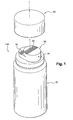
- the device 100 shown in its entirety in Figure 1 comprises a cylindrical container 20, in particular aluminum or tinplate, surmounted by a head 30 for actuating a valve 10, which will be described in detail later.
- the device 100 is provided for dispensing a composition, in particular a capillary composition, through a dispensing orifice 31.
- the dispensing head 30 comprises two bearing surfaces 32 and 33 intended for actuating the valve.
- a removable cap 40 covers the dispensing head 30.
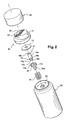
- valve 10 is mounted on a cup 60, which is expanded on a rolled edge of an aluminum container 20.
- cup 60 which is expanded on a rolled edge of an aluminum container 20. The latter is only partially represented.
- the valve 10 with a longitudinal axis X, comprises a cylindrical valve body 11, one end of which terminates in an axial chimney 12 on which is mounted a plunger tube 50.
- valve body 11 The other end of the valve body 11 is closed by the valve cup 60, the sealing at the closure being provided by an annular seal 13.
- An annular ring 11a formed inside the valve body 11 in the vicinity of the cup 60 is sealingly applied against the inner surface of the seal 13, thus ensuring both a holding in position thereof and the required seal.
- a portion 14a emerges outside the valve body.
- the valve stem 14 is traversed axially by a channel 18 whose one end opens out of the valve body via an axial orifice 18a.
- the channel 18 opens at the second end 14b of the valve stem by a frustoconical orifice 18c formed in the X axis.
- the lower end 14b of the valve stem 14 is located inside the valve body 11.
- a nacelle 15 having a bottom 15b surrounded by a peripheral lip 15a is mounted inside the valve body, the bottom 15b being provided in its middle, a frustoconical pin 15c.
- the nacelle 15 is formed in the extension of a rod portion 15d.
- a spring 16 surrounds the rod portion 15d and, in the absence of stress acting on the valve stem, forces the free end of the annular lip 15a into sealing engagement against the seal 13.
- An annular space 17 is then delimited by the nacelle 15, the lip 15a and the annular seal 13.
- the pin 15c is housed in the orifice 18c of the valve stem so as to seal it sealingly.
- the rod 14 is also pushed outwardly of the valve body by the spring, through the nacelle which bears on the lower end 14b of the rod. However, the rod 14 is held integral with the valve body due to the presence of an annular rod 19 formed on the rod to near its lower end 14b, the rod 19 abuts against the annular seal 13.
- the pin 15c facilitates the positioning of the rod 14 relative to the nacelle 15.
- a dispensing head 30 in the form of a push button.
- the dispensing head 30 is traversed by a passage 34, one end of which is in communication with the channel 18 of the valve stem.
- the other end of the passage 34 opens, via a dispensing orifice 31, delimited, for example, by a vortex channel nozzle (which is not shown in detail).
- the dispensing head comprises a first bearing surface 32 formed at a distance from the X axis and which makes it possible to actuate the valve by tilting.
- the dispensing head has a second bearing surface 33, passing through the axis X of the valve stem and preferably perpendicular to this axis X, which allows to actuate the valve by axial depression.
- the valve stem By exerting a force F 1 on the surface 33 of the dispensing head (FIG. 4), the valve stem penetrates axially by a distance such that the orifice 18b is no longer opposite the annular seal 13. against, the bottom 15b of the nacelle remains in abutment on the lower end 14b of the valve stem so that the orifice 18c remains closed sealingly by the pin 15c.
- the annular lip 15a moves away from the seal 13 over its entire circumference so that the product rushes into the channel 18 of the valve stem through the orifice 18b. It is then dispensed via the dispensing orifice 31, for example in the form of a spray, at a first rate determined by the section of the orifice 18b which is smaller than that of the channel 18.
- the product contained in the valve body then engulfs in the channel 18 of the valve stem 14 only through the orifice 18c. It goes up in the passage 34 of the dispensing head 30 and leaves in the form of a cloud of fine droplets, via the orifice 31 at a second flow rate, different from the first and which is determined by the section of the second orifice 18c.
- the second flow rate is determined by this section, regardless of the angle of inclination of the rod 14.
- the channel 18 comprises a necking 118 located axially between the first passage 18b and the second passage 18c while the orifice 18c may have a relatively large section, as shown in Figure 6.
- the second flow is then determined by the shrink 118. There is then a better control of the second debit.
- the bottom 15b of the nacelle may be devoid of pin.
- the bottom is then only constituted by a flat surface which bears on the end 14b of the rod to close the orifice 18c.
- the bottom of the nacelle is provided with a flat gasket 15e, for example an elastomer seal which improves the sealing of the orifice 18c.
- the valve just described may also allow the product to be dispensed at a third rate. Indeed, it is sufficient to push the valve stem 14 and tilt once it is depressed so as to clear the two orifices 18b and 18c. The product can then be distributed in a third rate, different from the first two.
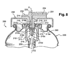
- the opening / closing element is a rod 214 secured to the push button 230. It can be obtained from molding in one piece with the push button. Alternatively, the rod 214 can be made separately and soldered to the push button, for example.
Landscapes
- Chemical & Material Sciences (AREA)
- Dispersion Chemistry (AREA)
- Engineering & Computer Science (AREA)
- Mechanical Engineering (AREA)
- Containers And Packaging Bodies Having A Special Means To Remove Contents (AREA)
- Nozzles (AREA)
- Check Valves (AREA)
- Sliding Valves (AREA)
Claims (17)
- Ventil (10; 210) vom Typ Kippventil zur Ausgabe eines in einem unter Druck stehenden Behälter (20; 220) enthaltenen Produkts, wobei das Ventil eine Längsachse X und ein Öffnungs-/Schließelement (14; 214) aufweist, das sich als Reaktion auf eine erste Betätigungssteuerung von einer Schließstellung in eine erste Öffnungsstellung verschieben kann, in der das unter Druck stehende Produkt in einer ersten Menge über einen ersten Durchlass (18b; 218b) ausgegeben wird, und das sich als Reaktion auf eine zweite, von der ersten unterschiedliche Betätigungssteuerung von der Schließstellung in eine zweite Öffnungsstellung verschieben kann, in der das Produkt in einer zweiten, von der ersten unterschiedlichen Menge über einen zweiten Durchlass (18c; 218c) ausgegeben wird, wobei der zweite Durchlass (18c; 218c) in der ersten Öffnungsstellung und der erste Durchlass (18b; 218b) in der zweiten Öffnungsstellung verschlossen ist.
- Ventil nach Anspruch 1, dadurch gekennzeichnet, dass das Öffnungs-/Schließelement (14; 214) sich als Reaktion auf die erste Betätigungssteuerung parallel zur Achse X bewegt und sich als Reaktion auf die zweite Betätigungssteuerung von der Achse X entfernt.
- Ventil nach einem der Ansprüche 1 oder 2, dadurch gekennzeichnet, dass das Öffnungs-/Schließelement (14; 214) von einem axialen Kanal (18) durchquert wird, der einerseits über eine Ausgangsöffnung (18a) nach außerhalb des Ventilkörpers mündet und andererseits in der Lage ist, über den ersten und den zweiten Durchlass (18b) und (18c) ins Innere des Ventilkörpers zu münden.
- Ventil nach dem vorhergehenden Anspruch, dadurch gekennzeichnet, dass der axiale Kanal (18) eine Verengung (118) aufweist, die sich axial zwischen dem ersten Durchlass (18b) und dem zweiten Durchlass (18c) befindet.
- Ventil nach einem der vorhergehenden Ansprüche, dadurch gekennzeichnet, dass das Öffnungs-/Schließelement (14) aus einer Ventilstange besteht, von der ein Abschnitt (14a) aus einem Ventilkörper (11) vorsteht.
- Ventil nach einem der Ansprüche 1 bis 4, dadurch gekennzeichnet, dass das Öffnungs-/Schließelement (214) eine fest mit einem außerhalb des Ventils befindlichen Organ, insbesondere einem Betätigungsorgan (230) des Ventils, verbundene Stange ist.
- Ventil nach einem der vorhergehenden Ansprüche, dadurch gekennzeichnet, dass es ein Dichtelement (13), insbesondere in Form einer Ringdichtung, aufweist, das im Inneren des Ventilkörpers (11) angeordnet ist, wobei der erste Durchlass (18b) in der Schließstellung seitlich vor dem Dichtelement (13) mündet.
- Ventil nach Anspruch 7, dadurch gekennzeichnet, dass der erste Durchlass (18b) in der ersten Öffnungsstellung im Inneren des Ventilkörpers (11) mündet.
- Ventil nach einem der vorhergehenden Ansprüche, dadurch gekennzeichnet, dass es außerdem ein Schiffchen (15) aufweist, das mit einer Lippe (15a) versehen ist, die in der Schließstellung auf dem Dichtelement (13) aufliegen kann, wobei das Schiffchen (15) außerdem einen Boden (15b) aufweist, der in der Schließstellung auf einem Ende (14b) des Öffnungs-/Schließelements aufliegt, um den zweiten Durchlass (18c) zu verschließen.
- Ventil nach Anspruch 9, dadurch gekennzeichnet, dass das Schiffchen (15) einen Zapfen (15c) aufweist, der sich in den zweiten Durchlass (18c) einfügen kann, um ihn insbesondere in der Schließstellung dicht zu verschließen.
- Ventil nach Anspruch 9, dadurch gekennzeichnet, dass der Boden (15b) des Schiffchens (15) eine Flachdichtung (15e) aufweist, die sich dicht auf das Ende (14b) des Öffnungs-/Schließelement (14) auflegen kann.
- Ventil nach einem der Ansprüche 9 bis 11, dadurch gekennzeichnet, dass das Ende (14b) des Öffnungs-/Schließelements sich vom Boden (15b) des Schiffchens entfernen kann, wenn das Öffnungs-/Schließelement (14) in der zweiten Öffnungsstellung ist, um den zweiten Durchlass (18c) freizulegen.
- Vorrichtung (100; 200) zur Verpackung und Ausgabe eines insbesondere kosmetischen Produkts, wobei die Vorrichtung einen unter Druck stehenden Behälter (20; 220) aufweist, der das auszugebende Produkt enthält, und mit einem Ventil (10; 210) gemäß einem der vorhergehenden Ansprüche ausgestattet ist.
- Vorrichtung nach Anspruch 13, dadurch gekennzeichnet, dass sie weiter ein Organ (30; 230) zur Betätigung des Ventils und zur Ausgabe des unter Druck stehenden Produkts über mindestens eine Ausgabeöffnung (31; 231) aufweist, die sich zum Beispiel innerhalb einer Düse, insbesondere einer Düse mit Wirbelstromwirkung, befindet.
- Vorrichtung nach dem vorhergehenden Anspruch, dadurch gekennzeichnet, dass das Betätigungsorgan (200) fest mit dem Öffnungs-/Schließelement (214) verbunden ist.
- Vorrichtung nach einem der Ansprüche 14 oder 15, dadurch gekennzeichnet, dass das Betätigungsorgan zwei unterschiedliche Auflageflächen (32, 33; 232, 233) zur Betätigung des Ventils aufweist, wobei eine erste Auflagefläche (32 ; 232) die seitliche Verschiebung des Öffnungs-/Schließelements und eine zweite Auflagefläche (33; 233) die axiale Verschiebung des Öffnungs/ Schließelements ermöglicht.
- Verwendung einer Vorrichtung (100; 200) nach einem der Ansprüche 13 bis 16 zur Verpackung und zur Ausgabe unter Druck eines kosmetischen Produkts, insbesondere eines Haarpflegeprodukts, eines Körperpflegeprodukts, eines Schminkprodukts, eines Hautpflegeprodukts oder eines Sonnenschutzprodukts.
Applications Claiming Priority (2)
| Application Number | Priority Date | Filing Date | Title |
|---|---|---|---|
| FR0350898A FR2862623B1 (fr) | 2003-11-25 | 2003-11-25 | Valve a basculement a debits independants |
| FR0350898 | 2003-11-25 |
Publications (2)
| Publication Number | Publication Date |
|---|---|
| EP1535860A1 EP1535860A1 (de) | 2005-06-01 |
| EP1535860B1 true EP1535860B1 (de) | 2006-10-25 |
Family
ID=34451742
Family Applications (1)
| Application Number | Title | Priority Date | Filing Date |
|---|---|---|---|
| EP04292631A Expired - Lifetime EP1535860B1 (de) | 2003-11-25 | 2004-11-05 | Kippventil mit variablem Durchfluss |
Country Status (6)
| Country | Link |
|---|---|
| EP (1) | EP1535860B1 (de) |
| JP (1) | JP4094003B2 (de) |
| AT (1) | ATE343532T1 (de) |
| DE (1) | DE602004002918T2 (de) |
| ES (1) | ES2274399T3 (de) |
| FR (1) | FR2862623B1 (de) |
Cited By (3)
| Publication number | Priority date | Publication date | Assignee | Title |
|---|---|---|---|---|
| US9554982B2 (en) | 2012-09-14 | 2017-01-31 | The Procter & Gamble Company | Aerosol antiperspirant compositions, products and methods |
| US9579265B2 (en) | 2014-03-13 | 2017-02-28 | The Procter & Gamble Company | Aerosol antiperspirant compositions, products and methods |
| EP4431190A4 (de) * | 2021-11-08 | 2025-11-12 | Mitani Valve Co Ltd | Mechanismus zum ausstossen von inhalten und mit diesem mechanismus zum ausstossen von inhalten ausgestattetes aerosolprodukt |
Families Citing this family (4)
| Publication number | Priority date | Publication date | Assignee | Title |
|---|---|---|---|---|
| JP5189411B2 (ja) * | 2008-05-30 | 2013-04-24 | 株式会社マンダム | エアゾール容器用バルブ、該バルブを備えたエアゾール容器、該エアゾール容器に内容物が充填されたエアゾール製品 |
| US9662285B2 (en) | 2014-03-13 | 2017-05-30 | The Procter & Gamble Company | Aerosol antiperspirant compositions, products and methods |
| JP6416515B2 (ja) * | 2014-04-03 | 2018-10-31 | 株式会社ダイゾー | 吐出容器 |
| JP6527242B2 (ja) | 2015-04-06 | 2019-06-05 | エス.シー. ジョンソン アンド サン、インコーポレイテッド | 放出システム |
Family Cites Families (4)
| Publication number | Priority date | Publication date | Assignee | Title |
|---|---|---|---|---|
| US3404863A (en) * | 1966-06-24 | 1968-10-08 | Derek B. Green | Aerosol valve assembly |
| US3795350A (en) * | 1972-10-16 | 1974-03-05 | Scovill Manufacturing Co | Aerosol valve having selectable flow rate |
| US4139128A (en) * | 1976-06-10 | 1979-02-13 | Seaquist Valve Co., A Division Of Pittway Corporation | Variable spray valve assembly |
| DE10121425B4 (de) * | 2001-05-02 | 2012-12-06 | Wella GmbH | Ventil für einen Druckgasbehälter |
-
2003
- 2003-11-25 FR FR0350898A patent/FR2862623B1/fr not_active Expired - Fee Related
-
2004
- 2004-11-05 ES ES04292631T patent/ES2274399T3/es not_active Expired - Lifetime
- 2004-11-05 DE DE602004002918T patent/DE602004002918T2/de not_active Expired - Lifetime
- 2004-11-05 EP EP04292631A patent/EP1535860B1/de not_active Expired - Lifetime
- 2004-11-05 AT AT04292631T patent/ATE343532T1/de not_active IP Right Cessation
- 2004-11-24 JP JP2004338359A patent/JP4094003B2/ja not_active Expired - Fee Related
Cited By (4)
| Publication number | Priority date | Publication date | Assignee | Title |
|---|---|---|---|---|
| US9554982B2 (en) | 2012-09-14 | 2017-01-31 | The Procter & Gamble Company | Aerosol antiperspirant compositions, products and methods |
| US9554981B2 (en) | 2012-09-14 | 2017-01-31 | The Procter & Gamble Company | Aerosol antiperspirant compositions, products and methods |
| US9579265B2 (en) | 2014-03-13 | 2017-02-28 | The Procter & Gamble Company | Aerosol antiperspirant compositions, products and methods |
| EP4431190A4 (de) * | 2021-11-08 | 2025-11-12 | Mitani Valve Co Ltd | Mechanismus zum ausstossen von inhalten und mit diesem mechanismus zum ausstossen von inhalten ausgestattetes aerosolprodukt |
Also Published As
| Publication number | Publication date |
|---|---|
| JP4094003B2 (ja) | 2008-06-04 |
| FR2862623A1 (fr) | 2005-05-27 |
| JP2005154013A (ja) | 2005-06-16 |
| ES2274399T3 (es) | 2007-05-16 |
| ATE343532T1 (de) | 2006-11-15 |
| DE602004002918D1 (de) | 2006-12-07 |
| DE602004002918T2 (de) | 2007-04-26 |
| FR2862623B1 (fr) | 2006-01-20 |
| EP1535860A1 (de) | 2005-06-01 |
Similar Documents
| Publication | Publication Date | Title |
|---|---|---|
| EP1035038B9 (de) | Einheit zur Aufbewahrung und Ausgabe eines unter Druck stehenden Produktes, insbesondere von Kosmetika | |
| CA2368052C (fr) | Dispositif pressurise equipe d'une valve a basculement | |
| CA2172192C (fr) | Distributeur aerosol a deux buses de pulverisation | |
| EP1291293A1 (de) | Ventil mit variablem Durchfluss und Behälter mit einem solchen Ventil | |
| EP1048590B1 (de) | Ventilbetätigungsvorrichtung und Einrichtung mit einer solchen Vorrichtung | |
| EP1288142B1 (de) | Einheit zur Aufbewahrung und Ausgabe eines unter Druck stehenden Produktes | |
| EP1561513B1 (de) | Blockierbarer Ausgabekopf | |
| CA2257485A1 (fr) | Valve a regulation de debit de sortie, et recipient equipe d'une telle valve | |
| CA2363285A1 (fr) | Tete de distribution nettoyable, et distributeur ainsi equipe | |
| FR2816290A1 (fr) | Dispositif de conditionnement et de distribution sous pression d'un produit | |
| CA2163483C (fr) | Pompe manuelle a precompression pour la pulverisation d'un liquide et ensemble de distribution equipe d'une telle pompe | |
| EP1201317B1 (de) | Spritzvorrichtung mit mindestens zwei Trägergasauslässen | |
| EP1535860B1 (de) | Kippventil mit variablem Durchfluss | |
| EP1302246B1 (de) | Einrichtung zum Zerstäuben von mindestens eines Produktes auf einem Substrat, insbesondere auf einem Keratinsubstrat wie Haut | |
| EP2295150B1 (de) | Druckknopf für ein Spendersystem mit unter Druck stehendem Produkt | |
| EP1588774B1 (de) | Verpackungseinheit mit Spenderkopf mit automatisch schliessender Öffnung | |
| EP1400465B1 (de) | Kippventil mit variablem Durchfluss und Behälter mit einem solchen Ventil | |
| FR2814727A1 (fr) | Valve destinee a equiper un dispositif pour la distribution sous pression d'un produit, et dispositif ainsi equipe | |
| FR2808258A1 (fr) | Recipient aerosol equipe d'une valve amelioree | |
| FR2760227A1 (fr) | Tete de distribution et distributeur equipe d'une telle tete | |
| FR2814726A1 (fr) | Valve destinee a equiper un dispositif pour la distribution sous pression d'un produit, et dispositif ainsi equipe | |
| FR2835812A1 (fr) | Dispositif de distribution protege contre un fonctionnement accidentel | |
| FR2876677A1 (fr) | Dispositif de distribution d'un produit cosmetique | |
| FR2892277A3 (fr) | Contenant pour des produits cosmetiques |
Legal Events
| Date | Code | Title | Description |
|---|---|---|---|
| PUAI | Public reference made under article 153(3) epc to a published international application that has entered the european phase |
Free format text: ORIGINAL CODE: 0009012 |
|
| AK | Designated contracting states |
Kind code of ref document: A1 Designated state(s): AT BE BG CH CY CZ DE DK EE ES FI FR GB GR HU IE IS IT LI LU MC NL PL PT RO SE SI SK TR |
|
| AX | Request for extension of the european patent |
Extension state: AL HR LT LV MK YU |
|
| 17P | Request for examination filed |
Effective date: 20051201 |
|
| AKX | Designation fees paid |
Designated state(s): AT BE BG CH CY CZ DE DK EE ES FI FR GB GR HU IE IS IT LI LU MC NL PL PT RO SE SI SK TR |
|
| GRAP | Despatch of communication of intention to grant a patent |
Free format text: ORIGINAL CODE: EPIDOSNIGR1 |
|
| GRAS | Grant fee paid |
Free format text: ORIGINAL CODE: EPIDOSNIGR3 |
|
| GRAA | (expected) grant |
Free format text: ORIGINAL CODE: 0009210 |
|
| AK | Designated contracting states |
Kind code of ref document: B1 Designated state(s): AT BE BG CH CY CZ DE DK EE ES FI FR GB GR HU IE IS IT LI LU MC NL PL PT RO SE SI SK TR |
|
| PG25 | Lapsed in a contracting state [announced via postgrant information from national office to epo] |
Ref country code: IT Free format text: LAPSE BECAUSE OF FAILURE TO SUBMIT A TRANSLATION OF THE DESCRIPTION OR TO PAY THE FEE WITHIN THE PRESCRIBED TIME-LIMIT;WARNING: LAPSES OF ITALIAN PATENTS WITH EFFECTIVE DATE BEFORE 2007 MAY HAVE OCCURRED AT ANY TIME BEFORE 2007. THE CORRECT EFFECTIVE DATE MAY BE DIFFERENT FROM THE ONE RECORDED. Effective date: 20061025 Ref country code: CZ Free format text: LAPSE BECAUSE OF FAILURE TO SUBMIT A TRANSLATION OF THE DESCRIPTION OR TO PAY THE FEE WITHIN THE PRESCRIBED TIME-LIMIT Effective date: 20061025 Ref country code: PL Free format text: LAPSE BECAUSE OF FAILURE TO SUBMIT A TRANSLATION OF THE DESCRIPTION OR TO PAY THE FEE WITHIN THE PRESCRIBED TIME-LIMIT Effective date: 20061025 Ref country code: AT Free format text: LAPSE BECAUSE OF FAILURE TO SUBMIT A TRANSLATION OF THE DESCRIPTION OR TO PAY THE FEE WITHIN THE PRESCRIBED TIME-LIMIT Effective date: 20061025 Ref country code: FI Free format text: LAPSE BECAUSE OF FAILURE TO SUBMIT A TRANSLATION OF THE DESCRIPTION OR TO PAY THE FEE WITHIN THE PRESCRIBED TIME-LIMIT Effective date: 20061025 Ref country code: NL Free format text: LAPSE BECAUSE OF FAILURE TO SUBMIT A TRANSLATION OF THE DESCRIPTION OR TO PAY THE FEE WITHIN THE PRESCRIBED TIME-LIMIT Effective date: 20061025 Ref country code: SI Free format text: LAPSE BECAUSE OF FAILURE TO SUBMIT A TRANSLATION OF THE DESCRIPTION OR TO PAY THE FEE WITHIN THE PRESCRIBED TIME-LIMIT Effective date: 20061025 Ref country code: SK Free format text: LAPSE BECAUSE OF FAILURE TO SUBMIT A TRANSLATION OF THE DESCRIPTION OR TO PAY THE FEE WITHIN THE PRESCRIBED TIME-LIMIT Effective date: 20061025 Ref country code: RO Free format text: LAPSE BECAUSE OF FAILURE TO SUBMIT A TRANSLATION OF THE DESCRIPTION OR TO PAY THE FEE WITHIN THE PRESCRIBED TIME-LIMIT Effective date: 20061025 Ref country code: IE Free format text: LAPSE BECAUSE OF FAILURE TO SUBMIT A TRANSLATION OF THE DESCRIPTION OR TO PAY THE FEE WITHIN THE PRESCRIBED TIME-LIMIT Effective date: 20061025 |
|
| REG | Reference to a national code |
Ref country code: GB Ref legal event code: FG4D Free format text: NOT ENGLISH |
|
| REG | Reference to a national code |
Ref country code: CH Ref legal event code: EP |
|
| REG | Reference to a national code |
Ref country code: IE Ref legal event code: FG4D Free format text: LANGUAGE OF EP DOCUMENT: FRENCH |
|
| PG25 | Lapsed in a contracting state [announced via postgrant information from national office to epo] |
Ref country code: MC Free format text: LAPSE BECAUSE OF NON-PAYMENT OF DUE FEES Effective date: 20061130 Ref country code: BE Free format text: LAPSE BECAUSE OF NON-PAYMENT OF DUE FEES Effective date: 20061130 |
|
| REF | Corresponds to: |
Ref document number: 602004002918 Country of ref document: DE Date of ref document: 20061207 Kind code of ref document: P |
|
| PG25 | Lapsed in a contracting state [announced via postgrant information from national office to epo] |
Ref country code: SE Free format text: LAPSE BECAUSE OF FAILURE TO SUBMIT A TRANSLATION OF THE DESCRIPTION OR TO PAY THE FEE WITHIN THE PRESCRIBED TIME-LIMIT Effective date: 20070125 Ref country code: DK Free format text: LAPSE BECAUSE OF FAILURE TO SUBMIT A TRANSLATION OF THE DESCRIPTION OR TO PAY THE FEE WITHIN THE PRESCRIBED TIME-LIMIT Effective date: 20070125 Ref country code: BG Free format text: LAPSE BECAUSE OF FAILURE TO SUBMIT A TRANSLATION OF THE DESCRIPTION OR TO PAY THE FEE WITHIN THE PRESCRIBED TIME-LIMIT Effective date: 20070125 |
|
| GBT | Gb: translation of ep patent filed (gb section 77(6)(a)/1977) |
Effective date: 20070108 |
|
| PG25 | Lapsed in a contracting state [announced via postgrant information from national office to epo] |
Ref country code: IS Free format text: LAPSE BECAUSE OF FAILURE TO SUBMIT A TRANSLATION OF THE DESCRIPTION OR TO PAY THE FEE WITHIN THE PRESCRIBED TIME-LIMIT Effective date: 20070225 |
|
| PG25 | Lapsed in a contracting state [announced via postgrant information from national office to epo] |
Ref country code: PT Free format text: LAPSE BECAUSE OF FAILURE TO SUBMIT A TRANSLATION OF THE DESCRIPTION OR TO PAY THE FEE WITHIN THE PRESCRIBED TIME-LIMIT Effective date: 20070326 |
|
| NLV1 | Nl: lapsed or annulled due to failure to fulfill the requirements of art. 29p and 29m of the patents act | ||
| REG | Reference to a national code |
Ref country code: ES Ref legal event code: FG2A Ref document number: 2274399 Country of ref document: ES Kind code of ref document: T3 |
|
| REG | Reference to a national code |
Ref country code: IE Ref legal event code: FD4D |
|
| PLBE | No opposition filed within time limit |
Free format text: ORIGINAL CODE: 0009261 |
|
| STAA | Information on the status of an ep patent application or granted ep patent |
Free format text: STATUS: NO OPPOSITION FILED WITHIN TIME LIMIT |
|
| 26N | No opposition filed |
Effective date: 20070726 |
|
| BERE | Be: lapsed |
Owner name: L'OREAL Effective date: 20061130 |
|
| PG25 | Lapsed in a contracting state [announced via postgrant information from national office to epo] |
Ref country code: GR Free format text: LAPSE BECAUSE OF FAILURE TO SUBMIT A TRANSLATION OF THE DESCRIPTION OR TO PAY THE FEE WITHIN THE PRESCRIBED TIME-LIMIT Effective date: 20070126 |
|
| PG25 | Lapsed in a contracting state [announced via postgrant information from national office to epo] |
Ref country code: EE Free format text: LAPSE BECAUSE OF FAILURE TO SUBMIT A TRANSLATION OF THE DESCRIPTION OR TO PAY THE FEE WITHIN THE PRESCRIBED TIME-LIMIT Effective date: 20061025 |
|
| PG25 | Lapsed in a contracting state [announced via postgrant information from national office to epo] |
Ref country code: HU Free format text: LAPSE BECAUSE OF FAILURE TO SUBMIT A TRANSLATION OF THE DESCRIPTION OR TO PAY THE FEE WITHIN THE PRESCRIBED TIME-LIMIT Effective date: 20070426 Ref country code: LU Free format text: LAPSE BECAUSE OF NON-PAYMENT OF DUE FEES Effective date: 20061105 Ref country code: TR Free format text: LAPSE BECAUSE OF FAILURE TO SUBMIT A TRANSLATION OF THE DESCRIPTION OR TO PAY THE FEE WITHIN THE PRESCRIBED TIME-LIMIT Effective date: 20061025 |
|
| PG25 | Lapsed in a contracting state [announced via postgrant information from national office to epo] |
Ref country code: CY Free format text: LAPSE BECAUSE OF FAILURE TO SUBMIT A TRANSLATION OF THE DESCRIPTION OR TO PAY THE FEE WITHIN THE PRESCRIBED TIME-LIMIT Effective date: 20061025 |
|
| REG | Reference to a national code |
Ref country code: CH Ref legal event code: PL |
|
| PG25 | Lapsed in a contracting state [announced via postgrant information from national office to epo] |
Ref country code: CH Free format text: LAPSE BECAUSE OF NON-PAYMENT OF DUE FEES Effective date: 20081130 Ref country code: LI Free format text: LAPSE BECAUSE OF NON-PAYMENT OF DUE FEES Effective date: 20081130 |
|
| PGFP | Annual fee paid to national office [announced via postgrant information from national office to epo] |
Ref country code: FR Payment date: 20131108 Year of fee payment: 10 Ref country code: GB Payment date: 20131030 Year of fee payment: 10 Ref country code: DE Payment date: 20131030 Year of fee payment: 10 |
|
| PGFP | Annual fee paid to national office [announced via postgrant information from national office to epo] |
Ref country code: ES Payment date: 20131011 Year of fee payment: 10 Ref country code: IT Payment date: 20131119 Year of fee payment: 10 |
|
| REG | Reference to a national code |
Ref country code: DE Ref legal event code: R119 Ref document number: 602004002918 Country of ref document: DE |
|
| GBPC | Gb: european patent ceased through non-payment of renewal fee |
Effective date: 20141105 |
|
| REG | Reference to a national code |
Ref country code: FR Ref legal event code: ST Effective date: 20150731 |
|
| PG25 | Lapsed in a contracting state [announced via postgrant information from national office to epo] |
Ref country code: GB Free format text: LAPSE BECAUSE OF NON-PAYMENT OF DUE FEES Effective date: 20141105 Ref country code: DE Free format text: LAPSE BECAUSE OF NON-PAYMENT OF DUE FEES Effective date: 20150602 |
|
| PG25 | Lapsed in a contracting state [announced via postgrant information from national office to epo] |
Ref country code: FR Free format text: LAPSE BECAUSE OF NON-PAYMENT OF DUE FEES Effective date: 20141201 |
|
| REG | Reference to a national code |
Ref country code: ES Ref legal event code: FD2A Effective date: 20151230 |
|
| PG25 | Lapsed in a contracting state [announced via postgrant information from national office to epo] |
Ref country code: IT Free format text: LAPSE BECAUSE OF NON-PAYMENT OF DUE FEES Effective date: 20141105 |
|
| PG25 | Lapsed in a contracting state [announced via postgrant information from national office to epo] |
Ref country code: ES Free format text: LAPSE BECAUSE OF NON-PAYMENT OF DUE FEES Effective date: 20141106 |