EP1205337A2 - Differentialbegrenzer für ein Differentialgetriebe - Google Patents
Differentialbegrenzer für ein Differentialgetriebe Download PDFInfo
- Publication number
- EP1205337A2 EP1205337A2 EP01126779A EP01126779A EP1205337A2 EP 1205337 A2 EP1205337 A2 EP 1205337A2 EP 01126779 A EP01126779 A EP 01126779A EP 01126779 A EP01126779 A EP 01126779A EP 1205337 A2 EP1205337 A2 EP 1205337A2
- Authority
- EP
- European Patent Office
- Prior art keywords
- clutch
- shaft
- clutch piston
- carrier
- cam
- Prior art date
- Legal status (The legal status is an assumption and is not a legal conclusion. Google has not performed a legal analysis and makes no representation as to the accuracy of the status listed.)
- Granted
Links
Images


Classifications
-
- F—MECHANICAL ENGINEERING; LIGHTING; HEATING; WEAPONS; BLASTING
- F16—ENGINEERING ELEMENTS AND UNITS; GENERAL MEASURES FOR PRODUCING AND MAINTAINING EFFECTIVE FUNCTIONING OF MACHINES OR INSTALLATIONS; THERMAL INSULATION IN GENERAL
- F16D—COUPLINGS FOR TRANSMITTING ROTATION; CLUTCHES; BRAKES
- F16D23/00—Details of mechanically-actuated clutches not specific for one distinct type
- F16D23/12—Mechanical clutch-actuating mechanisms arranged outside the clutch as such
-
- B—PERFORMING OPERATIONS; TRANSPORTING
- B60—VEHICLES IN GENERAL
- B60K—ARRANGEMENT OR MOUNTING OF PROPULSION UNITS OR OF TRANSMISSIONS IN VEHICLES; ARRANGEMENT OR MOUNTING OF PLURAL DIVERSE PRIME-MOVERS IN VEHICLES; AUXILIARY DRIVES FOR VEHICLES; INSTRUMENTATION OR DASHBOARDS FOR VEHICLES; ARRANGEMENTS IN CONNECTION WITH COOLING, AIR INTAKE, GAS EXHAUST OR FUEL SUPPLY OF PROPULSION UNITS IN VEHICLES
- B60K17/00—Arrangement or mounting of transmissions in vehicles
- B60K17/34—Arrangement or mounting of transmissions in vehicles for driving both front and rear wheels, e.g. four wheel drive vehicles
- B60K17/344—Arrangement or mounting of transmissions in vehicles for driving both front and rear wheels, e.g. four wheel drive vehicles having a transfer gear
- B60K17/346—Arrangement or mounting of transmissions in vehicles for driving both front and rear wheels, e.g. four wheel drive vehicles having a transfer gear the transfer gear being a differential gear
-
- B—PERFORMING OPERATIONS; TRANSPORTING
- B60—VEHICLES IN GENERAL
- B60K—ARRANGEMENT OR MOUNTING OF PROPULSION UNITS OR OF TRANSMISSIONS IN VEHICLES; ARRANGEMENT OR MOUNTING OF PLURAL DIVERSE PRIME-MOVERS IN VEHICLES; AUXILIARY DRIVES FOR VEHICLES; INSTRUMENTATION OR DASHBOARDS FOR VEHICLES; ARRANGEMENTS IN CONNECTION WITH COOLING, AIR INTAKE, GAS EXHAUST OR FUEL SUPPLY OF PROPULSION UNITS IN VEHICLES
- B60K23/00—Arrangement or mounting of control devices for vehicle transmissions, or parts thereof, not otherwise provided for
- B60K23/02—Arrangement or mounting of control devices for vehicle transmissions, or parts thereof, not otherwise provided for for main transmission clutches
-
- F—MECHANICAL ENGINEERING; LIGHTING; HEATING; WEAPONS; BLASTING
- F16—ENGINEERING ELEMENTS AND UNITS; GENERAL MEASURES FOR PRODUCING AND MAINTAINING EFFECTIVE FUNCTIONING OF MACHINES OR INSTALLATIONS; THERMAL INSULATION IN GENERAL
- F16D—COUPLINGS FOR TRANSMITTING ROTATION; CLUTCHES; BRAKES
- F16D23/00—Details of mechanically-actuated clutches not specific for one distinct type
- F16D23/12—Mechanical clutch-actuating mechanisms arranged outside the clutch as such
- F16D2023/123—Clutch actuation by cams, ramps or ball-screw mechanisms
-
- F—MECHANICAL ENGINEERING; LIGHTING; HEATING; WEAPONS; BLASTING
- F16—ENGINEERING ELEMENTS AND UNITS; GENERAL MEASURES FOR PRODUCING AND MAINTAINING EFFECTIVE FUNCTIONING OF MACHINES OR INSTALLATIONS; THERMAL INSULATION IN GENERAL
- F16H—GEARING
- F16H48/00—Differential gearings
- F16H2048/02—Transfer gears for influencing drive between outputs
- F16H2048/04—Transfer gears for influencing drive between outputs having unequal torque transfer between two outputs
-
- F—MECHANICAL ENGINEERING; LIGHTING; HEATING; WEAPONS; BLASTING
- F16—ENGINEERING ELEMENTS AND UNITS; GENERAL MEASURES FOR PRODUCING AND MAINTAINING EFFECTIVE FUNCTIONING OF MACHINES OR INSTALLATIONS; THERMAL INSULATION IN GENERAL
- F16H—GEARING
- F16H48/00—Differential gearings
- F16H48/06—Differential gearings with gears having orbital motion
- F16H48/10—Differential gearings with gears having orbital motion with orbital spur gears
-
- F—MECHANICAL ENGINEERING; LIGHTING; HEATING; WEAPONS; BLASTING
- F16—ENGINEERING ELEMENTS AND UNITS; GENERAL MEASURES FOR PRODUCING AND MAINTAINING EFFECTIVE FUNCTIONING OF MACHINES OR INSTALLATIONS; THERMAL INSULATION IN GENERAL
- F16H—GEARING
- F16H48/00—Differential gearings
- F16H48/20—Arrangements for suppressing or influencing the differential action, e.g. locking devices
- F16H48/22—Arrangements for suppressing or influencing the differential action, e.g. locking devices using friction clutches or brakes
Definitions
- the present invention relates to a differential limiting device for a differential device, and particularly a differential limiting device for a differential device having a clutch mechanism.
- a differential device is provide with a differential limiting device which additionally applies a predetermined differential limiting torque as an initial torque, and when one of the output shafts slips, it transmits a torque to the other output shaft by bypassing the one of output shaft.
- a differential limiting device comprising a hydraulic multiple disc clutch is known.
- a hydraulic multiple disc clutch is provided between a carrier and a drive shaft.
- the hydraulic multiple disc clutch generates a differential limiting torque depending on a slip of the rear wheel or the like.
- a differential limiting torque is generated by a multiple disc type clutch mechanism. Accordingly, a relatively large torque can be generated.
- the hydraulic multiple disc clutch needs a hydraulic mechanism for carrying out an engaging control of the clutch mechanism. Accordingly, the structure thereof becomes complicated. In some layout of the differential device, it is difficult to secure a hydraulic pressure source.
- a differential limiting device for a differential device which limits relative rotations of a shaft for inputting and outputting drive power to a carrier and the carrier aligned with the shaft comprising:
- the differential device is a planetary gear type differential device including a sun gear provided on the shaft, pinions being meshed with the sun gear, and pinion shafts for rotatably supporting the pinions on the carrier, and wherein the protruded parts are formed with the pinion shafts protruded from the carrier.
- a maximum shift of the clutch piston by the cam crests in the axial direction is smaller than a stroke length of the clutch piston within which the clutch piston is retractively movable, and the cam crests are continuously formed in a ring shape.
- each of the cam crests has cam surfaces that are configured to be asymmetrical with respect to a direction of its rotation relative to the protruded part.
- an embodiment of the differential limiting device according to the present invention may further comprises:
- an embodiment of the differential limiting device according to the present invention may further comprises:
- Figs. 1 through 7 show a first embodiment of the invention.
- Fig. 1 is a schematic diagram showing a power distribution system for a four-wheel drive vehicle, which is a first embodiment of the invention.
- Fig. 2 is a sectional view showing a center differential device.
- Fig. 3 is a perspective view showing a clutch piston.
- Fig. 4 is a development showing a cam part.
- Fig. 5 is an explanatory diagram useful in explaining an operation of a clutch piston, which is based on cam crests.
- Fig. 6 is an explanatory diagram for explaining a modification of a cam crest.
- Fig. 7 is an explanatory diagram for explaining another modification of a cam crest.
- reference numeral 1 designates a transaxel, vertically mounted, which is a drive system for a four-wheel drive vehicle.
- the transaxel 1 includes a torque converter case 2 and a differential case 3, which are disposed in the front part of the transaxel 1, while being formed integrally with the transaxel 1.
- a transmission case 4 is joined to the rear ends of those cases 2 and 3.
- An extension case 5 is joined to the rear end of the transmission case 4.
- a power transmission device is installed within the extension case 5.
- An oil pan 6 is mounted on the lower side of the transmission case 4.
- Reference numeral 10 designates an engine.
- a crank shaft 11 of the engine 10 is coupled to the input of a torque converter 13 having a lockup clutch 12, which is disposed within the torque converter case 2.
- a transmission input shaft 14 of an automatic transmission 30, which is placed in the transmission case 4, is coupled to the output side of the torque converter 13.
- An output shaft (transmission output shaft) 15 of the automatic transmission 30 is aligned with the input shaft (transmission input shaft) 14.
- the transmission output shaft 15 is coupled to the input of a center differential device 50, which is placed in the extension case 5.
- a front drive shaft 16 and a rear drive shaft 20 as a shaft part are coupled in a branched fashion to the output of the center differential device 50.
- the front drive shaft 16 is disposed in parallel with the input shaft 14 and the transmission output shaft 15 within the transmission case 4.
- the rear end of the front drive shaft 16 is coupled to the center differential device 50, through a pair of reduction gears 17 and 18.
- the front end of the front drive shaft 16 is provided to a front differential device 19, which is disposed within the differential case 3.
- the front wheel output shaft (not shown) for supporting the front wheels by shaft is coupled to the front differential device 19.
- the rear drive shaft 20 is provided to the rear wheel output shaft (not shown) for supporting the rear wheels by shaft, through a propeller shaft 21, a rear differential device 22, and the like.
- the automatic transmission 30 includes a front planetary gear 31 and a rear planetary gear 32.
- the front planetary gear 31 is provided with a high clutch 33, a reverse clutch 34, a brake band 35, a forward clutch 36, an overuning clutch 37, a low/reverse clutch 38, and one-way clutches 39 and 40.
- Some of those friction engaging elements are selectively engaged, thereby constructing a speed change stage of a forward 4-speed and reverse 1-speed.
- an oil pump 41 couples an impeller sleeve 13a with a drive shaft 42, and always drives them.
- a control valve body 43 is contained in the oil pan 6. The control valve body 43 supplies oil to the above friction engaging elements and discharges oil from them, thereby individually controlling the engagement and disengagement of those elements.
- the center differential device 50 consists of a differential device of the planetary gear type. Specifically, as shown in Fig. 2, a first sun gear 51 of large diameter is integral with the transmission output shaft 15. A plurality (e.g., three) of first pinions 52 of small diameter are engaged with the first sun gear 51, while being equidistantly spaced.
- a second sun gear 53 of small diameter is integral with the rear drive shaft 20.
- a plurality (e.g., three) of second pinions 54 of large diagram are meshed with the second sun gear 53, while being equidistantly spaced.
- the first and second pinions 52 and 54 are formed integrally with pinion members 55, respectively.
- the pinion members 55 are rotatably supported on pinion shafts 57 fastened to a carrier 56.
- the transmission output shaft 15 is set at the front end of the carrier 56, and inserted into the carrier and is rotatable therein.
- the rear drive shaft 20 is set at the rear end of the carrier and inserted into the carrier and is rotatable therein.
- the first sun gear 51 and the second sun gear 53 are placed in the central space thereof.
- the pinion shafts 57 are horizontally arranged so that the first pinions 52 is meshed with the first sun gear 51, and the second pinions 54 is meshed with the second sun gear 53.
- the reduction gear 17 is fastened to the carrier 56.
- a drive power that is transmitted through the pinion shafts 57 to the carrier 56, as shown in Fig. 1, is transmitted to the front wheels by way of the reduction gears 17 and 18, the front drive shaft 16 and the front differential device 19.
- a drive force that is transmitted from the rear drive shaft 20 to the second sun gear 53 is transmitted to the rear wheels by way of the rear differential device 22.
- a differential limiting device 60 of a multiple disc mechanism type is provided on the rear part of the center differential device 50, thereby effecting a differential limiting between the front and rear wheels.
- the differential limiting device 60 is made up of a clutch drum 61 fixed to the rear end of the carrier 56, and a clutch hub 62 spline-coupled to the rear drive shaft 20 within the clutch drum 61.
- a clutch piston 63 is spline-coupled to the outer peripheral surface of the clutch hub 62, and the clutch piston 63 is retractively movable in a direction along the rear drive shaft 20.
- the clutch piston 63 is spline-coupled to the clutch hub 62, so that it is allowed to retractively move in the direction along the rear drive shaft 20, and it is rotated together with the rear drive shaft 20. As a result, it is retractively and rotatably movable relative to the clutch drum 61.
- a tubular part 63a is formed integral with the rear end of the clutch piston 63 in a state that the outer peripheral surface of the tubular part 63a is confronted with the inner peripheral surface of the clutch drum 61.
- a plurality of drive plates 65 spline-coupled to the tubular part 63a and a plurality of driven plates 66 coupled to the clutch drum 61 are alternately arranged along the rear drive shaft 20 between the clutch drum 61 and the tubular part 63a.
- a retainer plate 67 spline-coupled to the clutch drum 61 is engaged and stopped at a snap ring 68, thereby forming a key part of a multiple disc clutch mechanism 70.
- the rear ends of the pinion shafts 57 are rearwardly extended, and protruded from the rear end of the carrier 56, and those protruded ones form protruded parts 75.
- Those protruded parts 75 are confronted with the front end of the clutch piston 63 within the clutch drum 61.
- a cam part 80 which is in sliding contact with the protruded parts 75, is formed on the front end of the clutch piston 63.
- cam crests 81 like configured are chained in a ring fashion (The number of cam crests 81 may appropriately be selected if it is within the number of pinion shafts).
- slanted cam surfaces 81b are symmetrically located on both sides of a top surface 81a.
- Each of the protruded parts 75 is put facing a position between the slanted cam surfaces 81b of the cam crests 81 (see Fig. 4).
- a distance from the front end face of the clutch piston 63 to the top surface 81a is longer than a stroke length of the clutch piston 63 within which the clutch piston 63 is retractively movable. This defines a slidable range of each protruded part 75 over the slanted cam surfaces 81b.
- a drive force generated by the engine 10 is first input to the input shaft 14 of the automatic transmission 30, through the torque converter 13 .
- a drive force having experienced a predetermined speed change in the automatic transmission 30 is output from the transmission output shaft 15, and input to the first sun gear 51 of the center differential device 50.
- the first pinions 52 which are meshed with the first sun gear 51, are formed integrally with the second pinions 54 which are meshed with the second sun gear 53 of the rear drive shaft 20. Since the reduction gear 18 of the front drive shaft 16 is meshed with the reduction gear 17 of the carrier 55, which supports the pinions 52 and 54. A torque output from the transmission output shaft 15 is distributed to the rear drive shaft 20 and the front drive shaft 16, through the center differential device 50.
- a torque distributed to the rear drive shaft 20 is transmitted to the rear wheel output shaft (not shown) for supporting the rear wheels, by way of the rear drive shaft 20, the propeller shaft 21 and the rear differential device 22.
- a torque distributed to the front drive shaft 16 is transmitted through the front differential device 19 to the front wheel shaft (not shown). As a result, the vehicle runs in four-wheel drive mode.
- the engaging control of the multiple disc clutch mechanism 70 is carried out with a simple structure including the protruded parts 75 provided on the end face of the carrier 56 and the cam part 80 provided on the surface of the clutch piston 63, which is confronted with the protruded parts 75. Therefore, there is no need of using a complicated hydraulic mechanism, and this leads to simplification of the structure of the differential limiting device 60. Further, such a mechanism does not need a hydraulic pressure source and others. Accordingly, a design freedom on the layout of the differential device or the like is increased.
- the pinion shafts 57 are formed protruding from the end face of the carrier 56, so that the number of required parts is reduced. This contributes further structure simplification of the differential limiting device 60.
- a distance from the front end face of the clutch piston 63 to the top surface 81a of the cam crests 81 is shorter than the stroke length within which the clutch piston 63 is retractively movable (Fig. 6(a)).
- the maximum shift "lmax" (see Fig. 6(b)) of the clutch piston 63 by the sliding of the protruded parts 75 relative to the cam crests 81 may be set to be smaller than the stroke length. Accordingly, the torque limiter function may be added to the differential limiting device 60.
- a slanting angle ⁇ 1 of the slanted cam surface 81b of each of the cam crests 81 is set to be different from a slanting angle ⁇ 2 of the slanted cam surface 81b.
- the cam crest 81 is configured to be asymmetrical with respect to a direction of its rotation relative to the protruded part 75. If so done, the characteristic of the differential limiting torque generated in the clutch mechanism 70 may be set so as to vary depending on a direction of the relative rotation of the carrier 56 and the rear drive shaft 20.
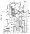
- Fig. 8 is a longitudinal sectional view showing a center differential device which is a second embodiment of the present invention.
- the second embodiment is different from the first embodiment in that coil springs 92 as elastic members are interposed between the clutch piston 63 and the multiple disc clutch mechanism 70. No description on the remaining portion of the second embodiment which are equal to or resembling the corresponding one of the first embodiment will be given by merely attaching like reference numerals to the related parts.
- a plurality of recesses 91 are formed in the surface of the clutch piston 63, which is confronted with the clutch mechanism 70.
- the coil spring 92 is held in each of the recesses 91.
- the rear ends of those coil springs 92 are protruded from the rear end of the clutch piston 63.
- the quantity of each coil spring 92 is selected to be longer than a gap ⁇ between the clutch piston 63 and the multiple disc clutch mechanism 70 under condition that the shift quantity "l" of the clutch piston 63 when it is shifted rearwardly is 0°.
- the coil springs 92 presses the multiple disc clutch mechanism 70 rearward by a given weak force.
- the second embodiment thus constructed produces the following advantageous effect, in addition to the effect by the first embodiment. Since the clutch piston 63 presses constantly the coil springs 92 by a weak force in the rearward direction, the multiple disc clutch mechanism 70 generates an initial torque.
- Fig. 9 is a longitudinal sectional view showing a center differential device, which is a third embodiment of the invention.
- the third embodiment is different from the first embodiment in that a dish spring 95 as an elastic member is placed in the multiple disc clutch mechanism 70.
- a dish spring 95 as an elastic member is placed in the multiple disc clutch mechanism 70.
- the multiple disc clutch mechanism 70 forms a gap ⁇ between the retainer plate 67 and the snap ring 68 when the shift quantity "l" of the clutch piston 63 when it is shifted rearwardly is 0°.
- a dish 95 having a squeeze, which is larger than the gap ⁇ , is interposed between the retainer plate 67 and the snap ring 68.
- the dish spring 95 presses forward the multiple disc clutch mechanism 70 (the drive plates 65 and the driven plates 66, and the like) by a weak force.
- the third embodiment produces the following advantageous effect in addition to the effect by the first embodiment. Since the dish spring 95 is constantly pressed by a weak force in the forward direction, the multiple disc clutch mechanism 70 generates an initial torque. By appropriately setting a spring constant of the dish spring 95, the characteristic of the torque generated by the multiple disc clutch mechanism 70 may variously be set with respective to the shift quantity of the clutch piston 63.
- the differential limiting device is provided in the planetary differential device. If required, a protruded part is formed integrally with the carrier of the bevel type differential device, whereby forming a similar differential limiting device is formed.
- the differential device to which the differential limiting device is applied is not limited to the center differential device. It is readily understood that the differential device may be applied to the front differential device, the rear differential device, or the like.
- the configuration of the slanted cam surfaces are not limited to the above one, as a matter of course.
- the slanted cam surfaces are curved, and a lift quantity of the clutch piston with respective to the relative rotations of the clutch piston and the cam is varied in an exponential function fashion.
Applications Claiming Priority (2)
| Application Number | Priority Date | Filing Date | Title |
|---|---|---|---|
| JP2000342347 | 2000-11-09 | ||
| JP2000342347A JP2002147570A (ja) | 2000-11-09 | 2000-11-09 | ディファレンシャル装置の差動制限装置 |
Publications (3)
| Publication Number | Publication Date |
|---|---|
| EP1205337A2 true EP1205337A2 (de) | 2002-05-15 |
| EP1205337A3 EP1205337A3 (de) | 2004-03-24 |
| EP1205337B1 EP1205337B1 (de) | 2006-02-08 |
Family
ID=18816925
Family Applications (1)
| Application Number | Title | Priority Date | Filing Date |
|---|---|---|---|
| EP01126779A Expired - Lifetime EP1205337B1 (de) | 2000-11-09 | 2001-11-09 | Differentialbegrenzer für ein Differentialgetriebe |
Country Status (4)
| Country | Link |
|---|---|
| US (1) | US6685594B2 (de) |
| EP (1) | EP1205337B1 (de) |
| JP (1) | JP2002147570A (de) |
| DE (1) | DE60117088T2 (de) |
Cited By (1)
| Publication number | Priority date | Publication date | Assignee | Title |
|---|---|---|---|---|
| DE10340912A1 (de) * | 2003-09-05 | 2005-04-07 | Gkn Driveline International Gmbh | Antriebsanordnung |
Families Citing this family (9)
| Publication number | Priority date | Publication date | Assignee | Title |
|---|---|---|---|---|
| US6962227B1 (en) * | 2004-05-07 | 2005-11-08 | Magna Drivetrain Of America, Inc. | Torque vectoring drive axle assembly |
| WO2006085941A1 (en) * | 2004-06-17 | 2006-08-17 | Anazaohealth Corporation | Copper-complex isonitrile positron emission tomography (pet) imaging agent and method |
| JP4028558B2 (ja) * | 2005-04-20 | 2007-12-26 | Gkn ドライブライン トルクテクノロジー株式会社 | 差動制限装置 |
| US7503416B2 (en) * | 2005-06-28 | 2009-03-17 | Magna Powertrain Usa, Inc. | Torque distributing drive mechanism with limited slip |
| JP4648884B2 (ja) * | 2006-09-11 | 2011-03-09 | 近畿車輌株式会社 | 車輪と作用体との自動隙間調整装置 |
| US9950617B2 (en) * | 2013-01-28 | 2018-04-24 | Eicher Polaris Private Limited | Side-by-side utility vehicle |
| DE102013215849A1 (de) * | 2013-08-12 | 2015-02-12 | Zf Friedrichshafen Ag | Antriebswandlervorrichtung und Achsgetriebevorrichtung mit einer Antriebswandlervorrichtung |
| US10668809B2 (en) * | 2017-06-07 | 2020-06-02 | American Axle & Manufacturing, Inc. | Method for controlling a vehicle having an all-wheel drive driveline with a disconnecting drive unit |
| WO2020264470A1 (en) * | 2019-06-28 | 2020-12-30 | Gkn Automotive Limited | Multi-stage shifting actuator for a vehicle power transfer unit |
Family Cites Families (15)
| Publication number | Priority date | Publication date | Assignee | Title |
|---|---|---|---|---|
| US3831462A (en) * | 1972-03-16 | 1974-08-27 | Eaton Corp | Limited slip differential |
| US4281749A (en) * | 1978-01-11 | 1981-08-04 | Borg-Warner Corporation | Automatic locking clutch |
| US4238013A (en) * | 1978-05-08 | 1980-12-09 | Eaton Corporation | Contact improver for clutch of a slip limiting differential |
| US4412459A (en) * | 1981-04-15 | 1983-11-01 | Eaton Corporation | Controlled differential |
| US4762021A (en) * | 1983-09-27 | 1988-08-09 | Tochigifujisangyo Kabushikigaisha | Transfer case for four-wheel-drive vehicles |
| EP0193160B1 (de) * | 1985-02-25 | 1992-09-16 | Tochigifujisangyo Kabushikikaisha | Leistungsübertragungsvorrichtung |
| GB8509056D0 (en) * | 1985-04-09 | 1985-05-15 | Smallfry Ltd | Differential gear drive |
| JP2636229B2 (ja) * | 1987-02-20 | 1997-07-30 | トヨタ自動車株式会社 | 四輪駆動用中央差動装置の差動制限機構 |
| JP2581965B2 (ja) * | 1988-08-30 | 1997-02-19 | 株式会社エフ・シー・シー | 動力伝達装置 |
| FR2666391A1 (fr) * | 1990-08-07 | 1992-03-06 | Glaenzer Spicer Sa | Dispositif de transmission a differentiel et accouplement notamment pour vehicule automobile. |
| JP2941077B2 (ja) * | 1991-03-25 | 1999-08-25 | 光洋精工株式会社 | 四輪駆動車用駆動力伝達装置 |
| JP3126770B2 (ja) | 1991-10-22 | 2001-01-22 | 富士重工業株式会社 | 多段自動変速機付車両 |
| US5465819A (en) * | 1992-09-29 | 1995-11-14 | Borg-Warner Automotive, Inc. | Power transmitting assembly |
| US5320586A (en) * | 1992-12-31 | 1994-06-14 | Dana Corporation | Locking limited slip planetary transfer case |
| JP3830992B2 (ja) * | 1995-09-13 | 2006-10-11 | Gkn ドライブライン トルクテクノロジー株式会社 | デファレンシャル装置 |
-
2000
- 2000-11-09 JP JP2000342347A patent/JP2002147570A/ja active Pending
-
2001
- 2001-11-09 DE DE60117088T patent/DE60117088T2/de not_active Expired - Fee Related
- 2001-11-09 EP EP01126779A patent/EP1205337B1/de not_active Expired - Lifetime
- 2001-11-09 US US10/037,692 patent/US6685594B2/en not_active Expired - Fee Related
Non-Patent Citations (1)
| Title |
|---|
| None |
Cited By (2)
| Publication number | Priority date | Publication date | Assignee | Title |
|---|---|---|---|---|
| DE10340912A1 (de) * | 2003-09-05 | 2005-04-07 | Gkn Driveline International Gmbh | Antriebsanordnung |
| DE10340912B4 (de) * | 2003-09-05 | 2006-04-06 | Gkn Driveline International Gmbh | Antriebsanordnung |
Also Published As
| Publication number | Publication date |
|---|---|
| EP1205337B1 (de) | 2006-02-08 |
| US6685594B2 (en) | 2004-02-03 |
| EP1205337A3 (de) | 2004-03-24 |
| DE60117088D1 (de) | 2006-04-20 |
| JP2002147570A (ja) | 2002-05-22 |
| DE60117088T2 (de) | 2006-11-02 |
| US20020055409A1 (en) | 2002-05-09 |
Similar Documents
| Publication | Publication Date | Title |
|---|---|---|
| US5098360A (en) | Differential gear with limited slip and locking mechanism | |
| JP4356679B2 (ja) | 摩擦係合装置 | |
| US4602525A (en) | Continuously variable speed transmission for a vehicle having a forward-reverse changeover mechanism | |
| JPH022022B2 (de) | ||
| EP1205337B1 (de) | Differentialbegrenzer für ein Differentialgetriebe | |
| KR100435278B1 (ko) | 휠트랜스미션 | |
| US6581745B2 (en) | Driving force distributing apparatus for a four-wheel drive vehicle | |
| US5913397A (en) | Clutch structure with piston having surface recessed from pressure surface for reducing stress concentration | |
| JPH03219123A (ja) | 連結装置 | |
| US7029415B2 (en) | Differential apparatus | |
| JP2003013996A (ja) | 摩擦係合装置 | |
| JP2015183730A (ja) | 車両用多板型電磁クラッチ装置 | |
| JP2581965B2 (ja) | 動力伝達装置 | |
| JP2003004065A (ja) | 摩擦係合装置 | |
| EP1058032A2 (de) | Schlupfbegrenztes Differential | |
| US11859674B1 (en) | Clutch device and motorcycle | |
| EP1126189A1 (de) | Übertragungswelle für Fahrzeug mit Allradantrieb | |
| KR100568033B1 (ko) | 수송용 멀티 쉬프팅 휠트랜스미션 | |
| CN113586697B (zh) | 扭矩管理器 | |
| JPS6248624B2 (de) | ||
| KR200238137Y1 (ko) | 차량용무단변속기 | |
| US20050204838A1 (en) | Multi-speed automatic layshaft transfer case | |
| KR19980049768A (ko) | 차량용 무단 변속장치 | |
| JPH0345259B2 (de) | ||
| NL8104734A (nl) | Transmissie voor een motorvoertuig, voorzien van een traploos variabele drijfriemoverbrenging. |
Legal Events
| Date | Code | Title | Description |
|---|---|---|---|
| PUAI | Public reference made under article 153(3) epc to a published international application that has entered the european phase |
Free format text: ORIGINAL CODE: 0009012 |
|
| AK | Designated contracting states |
Kind code of ref document: A2 Designated state(s): AT BE CH CY DE DK ES FI FR GB GR IE IT LI LU MC NL PT SE TR |
|
| AX | Request for extension of the european patent |
Free format text: AL;LT;LV;MK;RO;SI |
|
| PUAL | Search report despatched |
Free format text: ORIGINAL CODE: 0009013 |
|
| AK | Designated contracting states |
Kind code of ref document: A3 Designated state(s): AT BE CH CY DE DK ES FI FR GB GR IE IT LI LU MC NL PT SE TR |
|
| AX | Request for extension of the european patent |
Extension state: AL LT LV MK RO SI |
|
| RIC1 | Information provided on ipc code assigned before grant |
Ipc: 7B 60K 17/20 A |
|
| 17P | Request for examination filed |
Effective date: 20040621 |
|
| 17Q | First examination report despatched |
Effective date: 20040825 |
|
| AKX | Designation fees paid |
Designated state(s): DE FR GB |
|
| GRAP | Despatch of communication of intention to grant a patent |
Free format text: ORIGINAL CODE: EPIDOSNIGR1 |
|
| GRAS | Grant fee paid |
Free format text: ORIGINAL CODE: EPIDOSNIGR3 |
|
| RIC1 | Information provided on ipc code assigned before grant |
Ipc: 7B 60K 17/16 A |
|
| GRAA | (expected) grant |
Free format text: ORIGINAL CODE: 0009210 |
|
| AK | Designated contracting states |
Kind code of ref document: B1 Designated state(s): DE FR GB |
|
| REG | Reference to a national code |
Ref country code: GB Ref legal event code: FG4D |
|
| REF | Corresponds to: |
Ref document number: 60117088 Country of ref document: DE Date of ref document: 20060420 Kind code of ref document: P |
|
| PLBE | No opposition filed within time limit |
Free format text: ORIGINAL CODE: 0009261 |
|
| STAA | Information on the status of an ep patent application or granted ep patent |
Free format text: STATUS: NO OPPOSITION FILED WITHIN TIME LIMIT |
|
| 26N | No opposition filed |
Effective date: 20061109 |
|
| EN | Fr: translation not filed | ||
| GBPC | Gb: european patent ceased through non-payment of renewal fee |
Effective date: 20061109 |
|
| PG25 | Lapsed in a contracting state [announced via postgrant information from national office to epo] |
Ref country code: GB Free format text: LAPSE BECAUSE OF NON-PAYMENT OF DUE FEES Effective date: 20061109 |
|
| PG25 | Lapsed in a contracting state [announced via postgrant information from national office to epo] |
Ref country code: FR Free format text: LAPSE BECAUSE OF FAILURE TO SUBMIT A TRANSLATION OF THE DESCRIPTION OR TO PAY THE FEE WITHIN THE PRESCRIBED TIME-LIMIT Effective date: 20070330 |
|
| PG25 | Lapsed in a contracting state [announced via postgrant information from national office to epo] |
Ref country code: FR Free format text: LAPSE BECAUSE OF FAILURE TO SUBMIT A TRANSLATION OF THE DESCRIPTION OR TO PAY THE FEE WITHIN THE PRESCRIBED TIME-LIMIT Effective date: 20060208 |
|
| PGFP | Annual fee paid to national office [announced via postgrant information from national office to epo] |
Ref country code: DE Payment date: 20081107 Year of fee payment: 8 |
|
| PG25 | Lapsed in a contracting state [announced via postgrant information from national office to epo] |
Ref country code: DE Free format text: LAPSE BECAUSE OF NON-PAYMENT OF DUE FEES Effective date: 20100601 |