EP1205009B1 - Aperture coupled slot array antenna - Google Patents
Aperture coupled slot array antenna Download PDFInfo
- Publication number
- EP1205009B1 EP1205009B1 EP00944164A EP00944164A EP1205009B1 EP 1205009 B1 EP1205009 B1 EP 1205009B1 EP 00944164 A EP00944164 A EP 00944164A EP 00944164 A EP00944164 A EP 00944164A EP 1205009 B1 EP1205009 B1 EP 1205009B1
- Authority
- EP
- European Patent Office
- Prior art keywords
- antenna
- transmission line
- slots
- signal
- slot
- Prior art date
- Legal status (The legal status is an assumption and is not a legal conclusion. Google has not performed a legal analysis and makes no representation as to the accuracy of the status listed.)
- Expired - Lifetime
Links
- 230000005540 biological transmission Effects 0.000 claims description 73
- 230000008878 coupling Effects 0.000 claims description 28
- 238000010168 coupling process Methods 0.000 claims description 28
- 238000005859 coupling reaction Methods 0.000 claims description 28
- 230000002093 peripheral effect Effects 0.000 claims description 16
- 238000000034 method Methods 0.000 claims description 12
- 239000000758 substrate Substances 0.000 claims description 12
- 230000010287 polarization Effects 0.000 claims description 10
- 230000005855 radiation Effects 0.000 claims description 8
- 230000003595 spectral effect Effects 0.000 description 4
- 238000005253 cladding Methods 0.000 description 1
- 238000005388 cross polarization Methods 0.000 description 1
- 230000003247 decreasing effect Effects 0.000 description 1
- 239000003989 dielectric material Substances 0.000 description 1
- 238000005530 etching Methods 0.000 description 1
- 238000010348 incorporation Methods 0.000 description 1
- 239000012811 non-conductive material Substances 0.000 description 1
- 239000013307 optical fiber Substances 0.000 description 1
- 230000001902 propagating effect Effects 0.000 description 1
- 238000000926 separation method Methods 0.000 description 1
Images




Classifications
-
- H—ELECTRICITY
- H01—ELECTRIC ELEMENTS
- H01P—WAVEGUIDES; RESONATORS, LINES, OR OTHER DEVICES OF THE WAVEGUIDE TYPE
- H01P1/00—Auxiliary devices
- H01P1/20—Frequency-selective devices, e.g. filters
- H01P1/2005—Electromagnetic photonic bandgaps [EPB], or photonic bandgaps [PBG]
-
- G—PHYSICS
- G03—PHOTOGRAPHY; CINEMATOGRAPHY; ANALOGOUS TECHNIQUES USING WAVES OTHER THAN OPTICAL WAVES; ELECTROGRAPHY; HOLOGRAPHY
- G03F—PHOTOMECHANICAL PRODUCTION OF TEXTURED OR PATTERNED SURFACES, e.g. FOR PRINTING, FOR PROCESSING OF SEMICONDUCTOR DEVICES; MATERIALS THEREFOR; ORIGINALS THEREFOR; APPARATUS SPECIALLY ADAPTED THEREFOR
- G03F7/00—Photomechanical, e.g. photolithographic, production of textured or patterned surfaces, e.g. printing surfaces; Materials therefor, e.g. comprising photoresists; Apparatus specially adapted therefor
- G03F7/004—Photosensitive materials
- G03F7/09—Photosensitive materials characterised by structural details, e.g. supports, auxiliary layers
- G03F7/091—Photosensitive materials characterised by structural details, e.g. supports, auxiliary layers characterised by antireflection means or light filtering or absorbing means, e.g. anti-halation, contrast enhancement
-
- H—ELECTRICITY
- H01—ELECTRIC ELEMENTS
- H01Q—ANTENNAS, i.e. RADIO AERIALS
- H01Q1/00—Details of, or arrangements associated with, antennas
- H01Q1/36—Structural form of radiating elements, e.g. cone, spiral, umbrella; Particular materials used therewith
-
- H—ELECTRICITY
- H01—ELECTRIC ELEMENTS
- H01Q—ANTENNAS, i.e. RADIO AERIALS
- H01Q13/00—Waveguide horns or mouths; Slot antennas; Leaky-waveguide antennas; Equivalent structures causing radiation along the transmission path of a guided wave
- H01Q13/10—Resonant slot antennas
- H01Q13/106—Microstrip slot antennas
-
- H—ELECTRICITY
- H01—ELECTRIC ELEMENTS
- H01Q—ANTENNAS, i.e. RADIO AERIALS
- H01Q13/00—Waveguide horns or mouths; Slot antennas; Leaky-waveguide antennas; Equivalent structures causing radiation along the transmission path of a guided wave
- H01Q13/20—Non-resonant leaky-waveguide or transmission-line antennas; Equivalent structures causing radiation along the transmission path of a guided wave
-
- H—ELECTRICITY
- H01—ELECTRIC ELEMENTS
- H01Q—ANTENNAS, i.e. RADIO AERIALS
- H01Q9/00—Electrically-short antennas having dimensions not more than twice the operating wavelength and consisting of conductive active radiating elements
- H01Q9/04—Resonant antennas
- H01Q9/16—Resonant antennas with feed intermediate between the extremities of the antenna, e.g. centre-fed dipole
- H01Q9/26—Resonant antennas with feed intermediate between the extremities of the antenna, e.g. centre-fed dipole with folded element or elements, the folded parts being spaced apart a small fraction of operating wavelength
- H01Q9/27—Spiral antennas
Definitions
- the present invention is related to planar broadband antennas and, more particularly, to an antenna for transmitting or receiving circularly-polarized signals.
- the directivity of a patch antenna can be increased by incorporation of a choke ring ground plane, but this increases the weight of the antenna.
- U.S. Patent No. 5,815,122, issued to Nurnberger et al. discloses a slot spiral antenna with a single spiral slot on one side of the antenna, and a spiral microstrip feed line on the reverse side. The reference teaches primarily a single-slot configuration which results in an antenna having a low directivity.
- planar antennas producing circularly-polarized radiation
- an additional component such as a low-noise amplifier
- planar antennas producing circularly-polarized radiation
- planar antenna which allows for the mounting of active circuitry on the antenna substrate.
- the invention concerns a planar antenna as specified in claims 1 and 17, a method for emitting a circularly-polarized signal as specified in claim 24 and a method for receiving such a signal specified in claim 28.
- Fig. 1 is a diagrammatical view showing the back side of a substantially planar antenna 10 for receiving or transmitting electromagnetic signals of wavelength ⁇ , in accordance with the present invention.
- a back surface 13 of the antenna 10 is bounded by a peripheral edge 17.
- the peripheral edge 17 encloses an antenna axis 11 oriented orthogonal to the back surface 13.
- the transmission line 21 includes an input end 23 for receiving or outputting the electromagnetic signals.
- the input end is electrically connected by a first conductive lead 12 to a connector 22, such as an RF connector, for interfacing with external circuitry.
- a terminal end 25 of the transmission line 21 is electrically connected to a load impedance 24 via a second conductive lead 14.
- the transmission line 21 is in the shape of a circular arc, where an inside edge 29 of the transmission line 21 lies at a radius of R and an outside edge 27 lies at a radius of R + w from the antenna axis 11.
- the guided wave length of the transmission line is equal to one or more transmitted (or received) wavelengths ⁇ .
- Fig. 2 is a cross-sectional view of the antenna 10 as indicated by the sectional arrows in Fig. 1.
- the antenna 10 comprises a substrate 19 of nonconductive or dielectric material having a thickness t , where the transmission line 21 is disposed on the back surface 13 of the substrate 19 and a conductive layer 31 is disposed on a front surface 15 of the substrate 19.
- the front surface 15 is likewise bounded by the peripheral edge 17.
- Fig. 3 is a diagrammatical view of the front side of the antenna 10 showing that the conductive layer 31 includes a plurality of similar curved, slotted openings 33, 35, 37, and 39, where each slotted opening 33, 35, 37, and 39 extends through the conductive layer 31 to the front surface 15 of the substrate 19.
- the antenna 10 may thus be fabricated from a two-layer printed circuit board (PCB), where the transmission line 21 and the slotted openings 33, 35, 37, and 39 can be formed by suitably etching portions of the respective cladding layers to form the slotted openings 33, 35, 37, and 39 and the transmission line 21.
- PCB printed circuit board
- the present invention is not limited to this number and may comprise m slotted openings of varying shapes and lengths, where m ⁇ 2, as explained in greater detail below.
- the slotted openings can be curved in shape as shown, or can be straight segments or a combination of both straight and curved segments, as described in greater detail below.
- the curved shapes can be a conical section (i.e., a circular, elliptical, parabolic, or hyperbolic arc), an Archimedean spiral, a logarithmic spiral, or an exponential spiral.
- Straight slotted openings are equivalent to dipoles and, as such, a single slotted opening produces a linearly polarized signal.
- an array of straight slotted openings can be used to transmit, or receive, a circularly-polarized signal, as described in greater detail below.
- Circular polarization can also be produced by using an array of curved slotted openings, where the respective slotted openings are curved in the direction of the desired circular polarization (i.e., a clockwise curvature to receive or transmit left-hand circularly polarized signals).
- curved slotted openings having the equivalent guided wave lengths of straight slotted openings, the physical size of the antenna can be reduced.
- the slotted openings 33, 35, 37, and 39 have respective axial ends 33a, 35a, 37a, and 39a proximate the antenna axis 11, and respective peripheral ends 33p, 35p, 37p, and 39p proximate the peripheral edge 17.
- Axial ends 33a, 35a, 37a, are, respectively, d 1 , d 2 , d 3 , and d 4 from the antenna axis 11 where d i ⁇ R . That is, the respective axial ends 33a, 35a, 37a, and 39a of the respective slotted opening 33, 35, 37, and 39 lie inside the circle of radius R defined by the transmission line 21 (here shown in phantom) on the opposite side of the substrate 19.
- electromagnetic energy is fed into the transmission line 21 and is electromagnetically coupled to the slotted opening 33, 35, 37, and 39.
- This coupling occurs at the four respective regions where the slotted openings 33, 35, 37, and 39 which lie on the front surface 15, are located most proximate to and directly opposite the transmission line 21 which lies on the back surface 13 of the planar antenna 10.
- a portion of the slotted opening 33 is located a distance equivalent to the substrate thickness t from the transmission line 21 at a coupling region 43.
- the electromagnetic energy passing through transmission line 21 will produce a radiating field across the slotted opening 33 in the coupling region 43.
- This electromagnetic energy will be similarly coupled into slotted openings 35, 37, and 39 at coupling regions 45, 47, and 49 respectively.
- the degree of coupling is a function of the thickness t of the substrate 19, the width w of the transmission line 21, the width v of the slotted opening 33, and the dielectric properties of the substrate 19.
- the antenna 10 is used to receive signals, radiation energy is received at the slotted openings 33, 35, 37, and 39 is coupled into the transmission line 21 at the respective coupling regions 43, 45, 47, and 49.
- electromagnetic energy radiated by the antenna 10 is emitted in both directions along the antenna axis 11.
- a reflector 40 may be emplaced in opposed parallel relationship to the back surface 13 of the antenna 10, as shown in Fig. 4.
- an enclosed cavity (not shown) could be used in place of the reflector 40 as is well-known in the relevant art.
- the radiation pattern emitted from the antenna 10, as well as the radiation pattern roll-off characteristics, can also be varied as desired by increasing or decreasing the separation between the reflector 40 and the antenna 10.
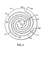
- Fig. 5 is the front view of a first embodiment of a planar antenna 50 in accordance with the present invention.
- the planar antenna 50 includes four similar spiral-shaped slotted openings 53, 55, 57, and 59 each of width v and guided wave length L GW symmetrically arrayed about an antenna axis 51 at angular intervals of ⁇ / 2 radians.
- This configuration provides for a phased-array slot antenna. Since the slotted openings 53, 55, 57, and 59 curve in the counter-clockwise direction, the transmitted or received signals will be right-hand polarized. Conversely, signals having a left-hand polarization are produced (or received) when the slotted openings 53, 55, 57, and 59 are curved in the clockwise direction.
- Unwanted cross-polarization is minimized by keeping the opening width v narrow in comparison to the guided wave length L GW .
- the shape of each of the slotted openings 53, 55, 57, and 59 can be described best in polar coordinates using the antenna axis 51 as origin.
- the radial distances r ( ⁇ ) of the interior edges of the slotted openings 53, 55, 57, and 59 increase from r a at the respective axial ends 53a, 55a, 57a, and 59a, to a maximum radius of r p at the respective peripheral ends 53p, 55p, 57p, and 59p.
- the radial distance from the antenna axis 51 to the inside edge of any of the slotted opening 53, 55, 57, and 59 increases with the polar angle ⁇ and is also a function of the interval spacing ⁇ r for each spiral-shaped slotted opening where ⁇ r ⁇ r ( ⁇ + 2 ⁇ ) - r ( ⁇ ).
- the slotted opening 55 is spatially offset from the slotted opening 53 by ⁇ / 2 radians (90°).
- the slotted opening 57 is spatially offset by ⁇ radians (180°)
- the slotted opening 59 is spatially offset by 3 ⁇ / 2 (270°).
- each spiral-shaped slotted opening subtends an angle of ⁇ p , where
- each of the slotted openings 53, 55, 57, and 59 is specified to be substantially smaller than the guided wave length and large enough to enable good electromagnetic coupling between the respective slotted opening 53, 55, 57, and 59 and a transmission line 61, best seen in Fig. 6 which is a rear view of the planar antenna 50.
- the transmission line 61 "crosses" each of the slotted openings 53, 55, 57, and 59 at respective coupling regions 63, 65, 67, and 69.
- the coupling regions 63, 65, 67, and 69 are offset by ⁇ / 2 radians (90°) from one another.
- This configuration provides for matching the electrical phase differences in the coupling regions 63, 65, 67, and 69 (i.e., differences of 90°) with the spatial differences of the slotted openings 53, 55, 57, and 59 when the guided wave length of the transmission line 61 is tuned to be one wavelength ⁇ .
- a single, omnidirectional beam is produced when the guided wave length of the transmission line 61 is one wavelength ⁇
- a squinted beam is produced when the guided wave length is less than one wavelength
- multiple directional beams are produced when the guided wave length of the transmission line 61 is more than one wavelength.
- a signal is transmitted (or received) by means of a signal source (or receiver) connected to an input/output end 62 of the transmission line 61 via a low-noise amplifier 71.
- a connector 75 provides for connecting the transmitted (or received) signal to external circuitry via a coaxial cable, an optical fiber, or a waveguide.
- An impedance load 73 is coupled to a terminal end 64 of the transmission line 61 to provide a leaky-wave antenna configuration and to thus ensure a uniform amplitude coupling to all slotted openings 53, 55, 57, and 59.
- the connector 75 can be directly attached to the input/output end 62 of the transmission line 61 and the amplifier 71 can be located on a separate circuit board.
- a transmitted signal originating in the low-noise amplifier 71 and terminating in the impedance load 73 passes through the transmission line 61 in a counter-clockwise direction (as viewed from the front of the planar antenna 50).
- the transmitted signal is successively coupled to the slotted openings 53, 55, 57, and 59 at the respective coupling regions 63, 65, 67, and 69, a right-hand polarized signal is emitted from the planar antenna 50.
- the signal can be transmitted through the transmission line 61 in a clockwise direction and the slotted openings 53, 55, 57, and 59 can be curved in a clockwise direction for a transmitted (or received) signal which is left-hand polarized.
- both right-hand and left-hand polarized radiation is transmitted (or received).
- an antenna 80 comprises an array of four slotted openings 81, 83, 85, and 89 coupled to the transmission line 61 (on the back side of the antenna 80).
- the slotted openings 81, 83, 85, and 87 each include a straight, radial segment 89 oriented at a right angle to the transmission line 61.
- the slotted openings 81, 83, 85, and 87 together with the respective radial segments 89 are tuned so as to optimally transmit (or receive) a specified wavelength ⁇ . Because slotted antennas are broadband, the antenna 80 can transmit (or receive) a spectral band of wavelengths, in addition to radiation of wavelength ⁇ .
- a slotted opening tuned to a guided wave length ⁇ can also be used for transmitting (or receiving) the spectral band wavelengths.
- a second slotted opening of different guided wave length is used for wavelengths lying outside this spectral band.
- an antenna 90 is configured to transmit and receive left-hand polarized signals at two wavelengths, ⁇ 1 and ⁇ 2 .
- Two slotted openings 91 and 95 are tuned for the longer wavelength ⁇ 1
- two slotted openings 93 and 97 are tuned for the shorter wavelength ⁇ 2 .
- the slotted opening 91 can be tuned to the wavelength ⁇ 1 by having a guided wave length L GW of: i) one wavelength ( ⁇ 1 ), ii) two wavelengths (2 ⁇ 1 ), iii) one-half wavelength ( ⁇ 1 / 2), iii) one-quarter wavelength ( ⁇ 1 / 4), or iv) some other multiple or fraction of a wavelength ( ⁇ 1 / b ).
- the antenna 90 comprises a transmission line 101 having a greater width in comparison to the width of transmission line 61 (in Fig. 6).
- a signal propagating within the transmission line 101 will appear mostly at the edges 103 and 105.
- the guided wave length along the inside edge 103 is smaller than the guided wave length along the outside edge 105 by the fraction R 1 / R 2 .
- the transmission line 101 can be optimized for coupling more than one wavelength into the array of slotted openings 91, 93, 95, and 97.
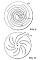
- an antenna 110 comprises six slotted openings 111 tuned to a first wavelength ⁇ 1 and six slotted openings 113 tuned to a second, shorter wavelength ⁇ 2 .
- the array of slotted openings 111 are disposed about an antenna axis 115 within the array of slotted openings 113.
- the six slotted openings 111 are spaced apart from one another at angular intervals of ⁇ / 3 radians (60°), and the six slotted openings 113 are spaced apart from one another at angular intervals of ⁇ / 3 radians (60°).
- All twelve slotted openings 111 and 113 are coupled to a transmission line (not shown) located on the back side of the antenna 110.
- the antenna 110 has a higher directivity and a greater pattern roll-off from boresight to antenna horizon than, for example, the antenna 50, in Fig. 5, comprising four slotted openings.
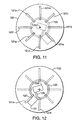
- an antenna 120 comprises eight straight slotted openings 121a, 121b,..., and 121h arrayed about an antenna axis 123.
- Each slotted opening 121a - 121h is coupled to a transmission line 125 on the back side of the antenna 120, as shown in Fig. 12.
- a first end 127 of the transmission line 125 is connected to a first signal amplifier 131, and a second end 129 of the transmission line 125 is connected to a second signal amplifier 133.
- a signal transmitted by the first signal amplifier 131 travels in a counter-clockwise direction, from the first end 127 to the second end 129.
- the input impedance of the second signal amplifier 133 provides an impedance load to the signal transmitted by the first signal amplifier 131.
- the counter-clockwise signal is coupled first into the straight slotted opening 121a and last into the straight slotted opening 121h. This coupling sequence produces an emitted signal having left-handed circular polarization.
- a signal transmitted by the second signal amplifier 133 travels in a clockwise direction, from the second end 129 to the first end 127.
- the input impedance of the first signal amplifier 131 provides an impedance load to the signal transmitted by the second signal amplifier 133.
- the clockwise signal is coupled first into the straight slotted opening 121h and last into the straight slotted opening 121a. This coupling sequence produces an emitted signal having right-handed circular polarization. In this way, a single antenna can be used to transmit signals of either polarization.
- the second signal amplifier 133 can be replaced by a receiver (not shown), and the antenna 120 can be used to transmit left-handed circularly polarized signals via first signal amplifier 121 and to receive right-handed circularly polarized signals via the receiver.
- the first signal amplifier is also replaced by a second receiver (not shown), both left-hand polarized and right-hand polarized signals can be received by the antenna 120.
Landscapes
- Physics & Mathematics (AREA)
- Electromagnetism (AREA)
- Optics & Photonics (AREA)
- Engineering & Computer Science (AREA)
- Architecture (AREA)
- Structural Engineering (AREA)
- General Physics & Mathematics (AREA)
- Waveguide Aerials (AREA)
- Variable-Direction Aerials And Aerial Arrays (AREA)
Applications Claiming Priority (3)
| Application Number | Priority Date | Filing Date | Title |
|---|---|---|---|
| US09/375,319 US6445354B1 (en) | 1999-08-16 | 1999-08-16 | Aperture coupled slot array antenna |
| US375319 | 1999-08-16 | ||
| PCT/IB2000/001030 WO2001013465A1 (en) | 1999-08-16 | 2000-07-26 | Aperture coupled slot array antenna |
Publications (2)
| Publication Number | Publication Date |
|---|---|
| EP1205009A1 EP1205009A1 (en) | 2002-05-15 |
| EP1205009B1 true EP1205009B1 (en) | 2003-10-22 |
Family
ID=23480406
Family Applications (1)
| Application Number | Title | Priority Date | Filing Date |
|---|---|---|---|
| EP00944164A Expired - Lifetime EP1205009B1 (en) | 1999-08-16 | 2000-07-26 | Aperture coupled slot array antenna |
Country Status (6)
| Country | Link |
|---|---|
| US (2) | US6445354B1 (https=) |
| EP (1) | EP1205009B1 (https=) |
| JP (1) | JP4700873B2 (https=) |
| AU (1) | AU762854B2 (https=) |
| DE (1) | DE60006132T2 (https=) |
| WO (1) | WO2001013465A1 (https=) |
Cited By (2)
| Publication number | Priority date | Publication date | Assignee | Title |
|---|---|---|---|---|
| RU2447553C1 (ru) * | 2010-08-20 | 2012-04-10 | Открытое акционерное общество "Федеральный научно-производственный центр "Нижегородский научно-исследовательский институт радиотехники" | Микрополосковое антенное переключающее устройство (мапу) |
| CN102570002A (zh) * | 2011-12-08 | 2012-07-11 | 浙江大学 | 毫米波单侧辐射全金属宽波束天线 |
Families Citing this family (87)
| Publication number | Priority date | Publication date | Assignee | Title |
|---|---|---|---|---|
| EP1099276A1 (en) * | 1998-06-26 | 2001-05-16 | Racal Antennas Limited | Signal coupling methods and arrangements |
| US6664932B2 (en) * | 2000-01-12 | 2003-12-16 | Emag Technologies, Inc. | Multifunction antenna for wireless and telematic applications |
| FR2817661A1 (fr) | 2000-12-05 | 2002-06-07 | Thomson Multimedia Sa | Dispositif pour la reception et/ou l'emission de signaux multifaisceaux |
| FR2825206A1 (fr) * | 2001-05-23 | 2002-11-29 | Thomson Licensing Sa | Dispositif pour la reception et/ou l'emission d'ondes electromagnetiques a rayonnement omnidirectionnel |
| FR2826512B1 (fr) * | 2001-06-22 | 2003-08-29 | Thomson Licensing Sa | Antenne compacte a fente annulaire |
| US7295154B2 (en) * | 2002-01-17 | 2007-11-13 | The Ohio State University | Vehicle obstacle warning radar |
| US7075493B2 (en) * | 2002-05-01 | 2006-07-11 | The Regents Of The University Of Michigan | Slot antenna |
| DE10231080A1 (de) * | 2002-07-09 | 2004-01-22 | Steffen Steinbach | Mikrowellenantenne |
| US6765542B2 (en) | 2002-09-23 | 2004-07-20 | Andrew Corporation | Multiband antenna |
| US6922175B2 (en) * | 2002-12-04 | 2005-07-26 | The Ohio State University | Radio transmission region in metallic panel |
| US6860081B2 (en) * | 2002-12-04 | 2005-03-01 | The Ohio State University | Sidelobe controlled radio transmission region in metallic panel |
| US7196657B2 (en) * | 2003-01-31 | 2007-03-27 | The Ohio State University | Radar system using RF noise |
| US6940457B2 (en) * | 2003-09-09 | 2005-09-06 | Center For Remote Sensing, Inc. | Multifrequency antenna with reduced rear radiation and reception |
| US7064714B2 (en) * | 2003-12-29 | 2006-06-20 | Transcore Link Logistics Corporation | Miniature circularly polarized patch antenna |
| DE102004002374A1 (de) * | 2004-01-15 | 2005-08-18 | Marconi Communications Gmbh | Verkleidung für eine Richtfunkantenne |
| US6977623B2 (en) * | 2004-02-17 | 2005-12-20 | Harris Corporation | Wideband slotted phased array antenna and associated methods |
| US7528728B2 (en) * | 2004-03-29 | 2009-05-05 | Impinj Inc. | Circuits for RFID tags with multiple non-independently driven RF ports |
| USD587691S1 (en) | 2004-03-29 | 2009-03-03 | Impinj, Inc. | Radio frequency identification tag antenna assembly |
| US7667589B2 (en) * | 2004-03-29 | 2010-02-23 | Impinj, Inc. | RFID tag uncoupling one of its antenna ports and methods |
| USD562810S1 (en) | 2004-03-29 | 2008-02-26 | Impinj, Inc. | Radio frequency identification tag antenna assembly |
| US7423539B2 (en) | 2004-03-31 | 2008-09-09 | Impinj, Inc. | RFID tags combining signals received from multiple RF ports |
| US6992624B2 (en) * | 2004-06-22 | 2006-01-31 | Novatel Inc. | Attitude determination system using null-steered array |
| EP1619754A1 (en) * | 2004-07-23 | 2006-01-25 | Nederlandse Organisatie voor toegepast-natuurwetenschappelijk Onderzoek TNO | Broadband leaky wave antenna |
| US7205939B2 (en) * | 2004-07-30 | 2007-04-17 | Novariant, Inc. | Land-based transmitter position determination |
| US7271766B2 (en) * | 2004-07-30 | 2007-09-18 | Novariant, Inc. | Satellite and local system position determination |
| US7315278B1 (en) * | 2004-07-30 | 2008-01-01 | Novariant, Inc. | Multiple frequency antenna structures and methods for receiving navigation or ranging signals |
| US7339526B2 (en) * | 2004-07-30 | 2008-03-04 | Novariant, Inc. | Synchronizing ranging signals in an asynchronous ranging or position system |
| US7342538B2 (en) * | 2004-07-30 | 2008-03-11 | Novariant, Inc. | Asynchronous local position determination system and method |
| US7339525B2 (en) * | 2004-07-30 | 2008-03-04 | Novariant, Inc. | Land-based local ranging signal methods and systems |
| US7532160B1 (en) * | 2004-07-30 | 2009-05-12 | Novariant, Inc. | Distributed radio frequency ranging signal receiver for navigation or position determination |
| US7339524B2 (en) * | 2004-07-30 | 2008-03-04 | Novariant, Inc. | Analog decorrelation of ranging signals |
| TWI239681B (en) * | 2004-12-22 | 2005-09-11 | Tatung Co Ltd | Circularly polarized array antenna |
| USD586336S1 (en) | 2004-12-30 | 2009-02-10 | Impinj, Inc. | Radio frequency identification tag antenna assembly |
| DE102005008063B4 (de) * | 2005-02-22 | 2008-05-15 | Fraunhofer-Gesellschaft zur Förderung der angewandten Forschung e.V. | Antenne |
| US7250916B2 (en) * | 2005-07-19 | 2007-07-31 | Novatel Inc. | Leaky wave antenna with radiating structure including fractal loops |
| US7429952B2 (en) * | 2005-12-23 | 2008-09-30 | Hemisphere Gps Inc. | Broadband aperture coupled GNSS microstrip patch antenna |
| USD570337S1 (en) * | 2006-08-25 | 2008-06-03 | Impinj, Inc. | Broken-loop RFID reader antenna for near field and far field UHF RFID tags |
| US20080048867A1 (en) * | 2006-01-18 | 2008-02-28 | Oliver Ronald A | Discontinuous-Loop RFID Reader Antenna And Methods |
| USD548225S1 (en) * | 2006-02-17 | 2007-08-07 | Impinj, Inc. | Radio frequency identification tag antenna assembly |
| US7657243B2 (en) * | 2006-03-21 | 2010-02-02 | Broadcom Corporation | RF transceiver front-end |
| TW200743260A (en) * | 2006-05-04 | 2007-11-16 | Tatung Co Ltd | Circular polarized antenna |
| JP4769629B2 (ja) * | 2006-05-12 | 2011-09-07 | 古野電気株式会社 | アンテナ装置及び受信装置 |
| US7265729B1 (en) * | 2006-07-31 | 2007-09-04 | National Taiwan University | Microstrip antenna having embedded spiral inductor |
| USD543976S1 (en) * | 2006-09-21 | 2007-06-05 | Impinj, Inc. | RFID antenna |
| JP4627295B2 (ja) * | 2006-10-23 | 2011-02-09 | 株式会社日本自動車部品総合研究所 | アンテナ装置 |
| US7394435B1 (en) * | 2006-12-08 | 2008-07-01 | Wide Sky Technology, Inc. | Slot antenna |
| DE102006058168B4 (de) * | 2006-12-09 | 2021-05-27 | Atmel Corp. | Antenne für einen rückstreubasierten RFID-Transponder |
| US20080180336A1 (en) * | 2007-01-31 | 2008-07-31 | Bauregger Frank N | Lensed antenna methods and systems for navigation or other signals |
| US7868841B2 (en) * | 2007-04-11 | 2011-01-11 | Vubiq Incorporated | Full-wave di-patch antenna |
| US8004474B2 (en) | 2007-09-17 | 2011-08-23 | Physical Sciences, Inc. | Non-cutoff frequency selective surface ground plane antenna assembly |
| US7889151B1 (en) * | 2007-11-08 | 2011-02-15 | The United States Of America As Represented By The Secretary Of The Navy | Passive wide-band low-elevation nulling antenna |
| USD574370S1 (en) * | 2008-02-14 | 2008-08-05 | Impinj, Inc. | Broken-loop RFID reader antenna for near field and far field UHF RFID tags |
| USD591733S1 (en) * | 2008-04-23 | 2009-05-05 | Nissei Limited | Television or communication antenna element comprising a high frequency wave coupler |
| USD591734S1 (en) * | 2008-09-22 | 2009-05-05 | Nissei Limited | Television or communication antenna element comprising a high frequency wave coupler |
| JP5323448B2 (ja) * | 2008-10-29 | 2013-10-23 | 古野電気株式会社 | スロットボウタイアンテナ |
| ES2711352T3 (es) | 2010-06-11 | 2019-05-03 | Ricoh Co Ltd | Dispositivo de almacenamiento de información, dispositivo extraíble, contenedor de revelador y aparato de formación de imágenes |
| GB201012923D0 (en) * | 2010-07-30 | 2010-09-15 | Sarantel Ltd | An antenna |
| US8928544B2 (en) * | 2011-02-21 | 2015-01-06 | Her Majesty The Queen In Right Of Canada As Represented By The Minister Of National Defence | Wideband circularly polarized hybrid dielectric resonator antenna |
| US8797222B2 (en) | 2011-11-07 | 2014-08-05 | Novatel Inc. | Directional slot antenna with a dielectric insert |
| MX337360B (es) * | 2012-04-19 | 2016-02-26 | Xg Technology Inc | Diseño de antena mimo utilizado en ambientes de desvanecimiento. |
| US9086477B2 (en) | 2012-06-06 | 2015-07-21 | Novatel Inc. | Anti-jamming subsystem employing an antenna array with a horizontal circular reception pattern |
| WO2014008508A1 (en) | 2012-07-06 | 2014-01-09 | The Ohio State University | Compact dual band gnss antenna design |
| US10158167B2 (en) | 2012-07-24 | 2018-12-18 | Novatel Inc. | Irridium/inmarsat and GNSS antenna system |
| RU2504055C1 (ru) * | 2012-08-10 | 2014-01-10 | Общество С Ограниченной Ответственностью Научно-Производственная Фирма "Электрон" | Щелевая полосковая антенна вытекающей волны с круговой поляризацией |
| CN102868007B (zh) * | 2012-09-18 | 2015-04-01 | 中国科学院光电技术研究所 | 一种基于手性人工电磁结构的双频圆极化器 |
| US9598945B2 (en) | 2013-03-15 | 2017-03-21 | Chevron U.S.A. Inc. | System for extraction of hydrocarbons underground |
| USD711859S1 (en) * | 2013-12-27 | 2014-08-26 | Megabyte Limited | Antenna for radio frequency tag reader |
| RU2580869C1 (ru) * | 2014-11-10 | 2016-04-10 | Федеральное государственное бюджетное учреждение науки Красноярский научный центр Сибирского отделения Российской академии наук (КНЦ СО РАН) | Щелевая полосковая антенна вытекающей волны с круговой поляризацией со скачком ширины щелевых излучателей |
| CN104752835A (zh) * | 2014-12-31 | 2015-07-01 | 中国电子科技集团公司第五十研究所 | 微带环串馈平面四臂槽螺旋天线 |
| US20180311937A1 (en) | 2015-06-30 | 2018-11-01 | Gauzy Ltd | Multiple and single layers liquid crystal dispersion devices for common and direct glazing applications and methods thereof |
| RU2619846C2 (ru) * | 2015-10-19 | 2017-05-18 | Федеральное государственное бюджетное научное учреждение "Федеральный исследовательский центр "Красноярский научный центр Сибирского отделения Российской академии наук" (ФИЦ КНЦ СО РАН, КНЦ СО РАН) | Широкополосная щелевая полосковая антенна гнсс |
| RU167585U1 (ru) * | 2015-12-28 | 2017-01-10 | федеральное государственное бюджетное образовательное учреждение высшего образования "Нижегородский государственный технический университет им. Р.Е. Алексеева" (НГТУ) | Многочастотная планарная щелевая антенна типа ракушка на две поляризации |
| US10666302B2 (en) * | 2016-06-21 | 2020-05-26 | Telefonaktiebolaget Lm Ericsson (Publ) | Antenna feed in a wireless communication network node |
| US10609568B2 (en) | 2017-04-03 | 2020-03-31 | Novatel Inc. | System and method for determining azimuth of a source of an interfering signal using a beam steering antenna |
| USD852172S1 (en) * | 2017-07-11 | 2019-06-25 | Shenzhen BITECA Electron Co., Ltd. | HDTV antenna |
| US11199611B2 (en) * | 2018-02-20 | 2021-12-14 | Magna Electronics Inc. | Vehicle radar system with T-shaped slot antennas |
| CN110400779B (zh) * | 2018-04-25 | 2022-01-11 | 华为技术有限公司 | 封装结构 |
| JP7041859B2 (ja) * | 2018-06-01 | 2022-03-25 | 株式会社Space Power Technologies | レクテナ装置 |
| CN111106428B (zh) * | 2018-10-26 | 2021-01-26 | 启碁科技股份有限公司 | 天线结构和电子装置 |
| US11169240B1 (en) | 2018-11-30 | 2021-11-09 | Ball Aerospace & Technologies Corp. | Systems and methods for determining an angle of arrival of a signal at a planar array antenna |
| US11327142B2 (en) | 2019-03-29 | 2022-05-10 | Ball Aerospace & Technologies Corp. | Systems and methods for locating and tracking radio frequency transmitters |
| RU193058U1 (ru) * | 2019-06-28 | 2019-10-11 | федеральное государственное бюджетное образовательное учреждение высшего образования "Нижегородский государственный технический университет им. Р.Е. Алексеева" (НГТУ) | Узкополосная двухщелевая ячейка с копланарными линиями и болометрами на холодных электронах для многочастотного массива антенн |
| US12580300B2 (en) * | 2019-07-03 | 2026-03-17 | Starkey Laboratories, Inc. | Circular polarized spiral antenna for hearing assistance devices |
| RU2738350C1 (ru) * | 2019-11-22 | 2020-12-11 | Федеральное государственное бюджетное образовательное учреждение высшего образования "Московский автомобильно-дорожный государственный технический университет (МАДИ) | Способ беспроводной передачи цифровой информации |
| WO2022159481A1 (en) * | 2021-01-19 | 2022-07-28 | Tesla, Inc. | Multi-band antenna |
| JP2024039960A (ja) * | 2022-09-12 | 2024-03-25 | 日之出水道機器株式会社 | 仕切部材および構造物 |
| JP2025141659A (ja) * | 2024-03-15 | 2025-09-29 | 株式会社デンソー | 電波吸収装置 |
Family Cites Families (25)
| Publication number | Priority date | Publication date | Assignee | Title |
|---|---|---|---|---|
| US3568206A (en) * | 1968-02-15 | 1971-03-02 | Northrop Corp | Transmission line loaded annular slot antenna |
| US3665480A (en) * | 1969-01-23 | 1972-05-23 | Raytheon Co | Annular slot antenna with stripline feed |
| US3696433A (en) * | 1970-07-17 | 1972-10-03 | Teledyne Ryan Aeronautical Co | Resonant slot antenna structure |
| JPS5183448A (ja) * | 1975-01-17 | 1976-07-22 | Mitsubishi Electric Corp | Hanshakyoantenayoichijihoshaki |
| SE7603520L (sv) * | 1976-03-22 | 1977-09-23 | Ericsson Telefon Ab L M | Antenn |
| US4204212A (en) | 1978-12-06 | 1980-05-20 | The United States Of America As Represented By The Secretary Of The Army | Conformal spiral antenna |
| US4315266A (en) | 1980-07-25 | 1982-02-09 | Nasa | Spiral slotted phased antenna array |
| US4477814A (en) * | 1982-08-02 | 1984-10-16 | The United States Of America As Represented By The Secretary Of The Air Force | Dual mode radio frequency-infrared frequency system |
| US4525720A (en) | 1982-10-15 | 1985-06-25 | The United States Of America As Represented By The Secretary Of The Navy | Integrated spiral antenna and printed circuit balun |
| US4608572A (en) * | 1982-12-10 | 1986-08-26 | The Boeing Company | Broad-band antenna structure having frequency-independent, low-loss ground plane |
| US4658262A (en) | 1985-02-19 | 1987-04-14 | Duhamel Raymond H | Dual polarized sinuous antennas |
| US5313216A (en) | 1991-05-03 | 1994-05-17 | Georgia Tech Research Corporation | Multioctave microstrip antenna |
| JP3283046B2 (ja) * | 1991-10-04 | 2002-05-20 | 尚久 後藤 | ダイバーシチアンテナ |
| US5402136A (en) * | 1991-10-04 | 1995-03-28 | Naohisa Goto | Combined capacitive loaded monopole and notch array with slits for multiple resonance and impedance matching pins |
| JPH05211407A (ja) * | 1991-12-20 | 1993-08-20 | Toppan Printing Co Ltd | 直線偏波ラジアルラインループアンテナ |
| US5220340A (en) | 1992-04-29 | 1993-06-15 | Lotfollah Shafai | Directional switched beam antenna |
| US5451973A (en) | 1993-11-02 | 1995-09-19 | Trw Inc. | Multi-mode dual circularly polarized spiral antenna |
| JP3464277B2 (ja) | 1994-06-20 | 2003-11-05 | 株式会社東芝 | 円偏波パッチアンテナ |
| US5712647A (en) | 1994-06-28 | 1998-01-27 | The United States Of America As Represented By The Administrator Of The National Aeronautics And Space Administration | Spiral microstrip antenna with resistance |
| US5621422A (en) | 1994-08-22 | 1997-04-15 | Wang-Tripp Corporation | Spiral-mode microstrip (SMM) antennas and associated methods for exciting, extracting and multiplexing the various spiral modes |
| US5646633A (en) | 1995-04-05 | 1997-07-08 | Mcdonnell Douglas Corporation | Microstrip antenna having a plurality of broken loops |
| US5614863A (en) | 1995-10-31 | 1997-03-25 | Ail Systems, Inc. | Method and system for increasing the power efficiency of a balanced amplifier/antenna combination |
| US5815122A (en) | 1996-01-11 | 1998-09-29 | The Regents Of The University Of Michigan | Slot spiral antenna with integrated balun and feed |
| US5936594A (en) | 1997-05-17 | 1999-08-10 | Raytheon Company | Highly isolated multiple frequency band antenna |
| US5929825A (en) | 1998-03-09 | 1999-07-27 | Motorola, Inc. | Folded spiral antenna for a portable radio transceiver and method of forming same |
-
1999
- 1999-08-16 US US09/375,319 patent/US6445354B1/en not_active Expired - Lifetime
-
2000
- 2000-07-26 EP EP00944164A patent/EP1205009B1/en not_active Expired - Lifetime
- 2000-07-26 AU AU58396/00A patent/AU762854B2/en not_active Expired
- 2000-07-26 JP JP2001517463A patent/JP4700873B2/ja not_active Expired - Lifetime
- 2000-07-26 WO PCT/IB2000/001030 patent/WO2001013465A1/en not_active Ceased
- 2000-07-26 DE DE60006132T patent/DE60006132T2/de not_active Expired - Lifetime
- 2000-12-08 US US09/732,849 patent/US6452560B2/en not_active Expired - Lifetime
Cited By (3)
| Publication number | Priority date | Publication date | Assignee | Title |
|---|---|---|---|---|
| RU2447553C1 (ru) * | 2010-08-20 | 2012-04-10 | Открытое акционерное общество "Федеральный научно-производственный центр "Нижегородский научно-исследовательский институт радиотехники" | Микрополосковое антенное переключающее устройство (мапу) |
| CN102570002A (zh) * | 2011-12-08 | 2012-07-11 | 浙江大学 | 毫米波单侧辐射全金属宽波束天线 |
| CN102570002B (zh) * | 2011-12-08 | 2014-02-19 | 浙江大学 | 毫米波单侧辐射全金属宽波束天线 |
Also Published As
| Publication number | Publication date |
|---|---|
| EP1205009A1 (en) | 2002-05-15 |
| WO2001013465A1 (en) | 2001-02-22 |
| JP2003507915A (ja) | 2003-02-25 |
| AU762854B2 (en) | 2003-07-10 |
| US6452560B2 (en) | 2002-09-17 |
| US6445354B1 (en) | 2002-09-03 |
| US20020067315A1 (en) | 2002-06-06 |
| DE60006132T2 (de) | 2004-06-09 |
| DE60006132D1 (de) | 2003-11-27 |
| AU5839600A (en) | 2001-03-13 |
| US20020011965A1 (en) | 2002-01-31 |
| JP4700873B2 (ja) | 2011-06-15 |
Similar Documents
| Publication | Publication Date | Title |
|---|---|---|
| EP1205009B1 (en) | Aperture coupled slot array antenna | |
| US7012572B1 (en) | Integrated ultra wideband element card for array antennas | |
| EP0873577B1 (en) | Slot spiral antenna with integrated balun and feed | |
| JP4440266B2 (ja) | 広帯域フェーズドアレイ放射器 | |
| US5006859A (en) | Patch antenna with polarization uniformity control | |
| KR950013142B1 (ko) | 환형 슬로트 안테나 | |
| US8830133B2 (en) | Circularly polarised array antenna | |
| US5070340A (en) | Broadband microstrip-fed antenna | |
| US7498989B1 (en) | Stacked-disk antenna element with wings, and array thereof | |
| US6124833A (en) | Radial line slot antenna | |
| US5173714A (en) | Slot array antenna | |
| CN115428262B (zh) | 具有中心馈电天线阵列的微带天线装置 | |
| US20050219126A1 (en) | Multi-beam antenna | |
| US20100231475A1 (en) | Circular waveguide antenna and circular waveguide array antenna | |
| KR20030040513A (ko) | 다중반사기 안테나를 위한 전자기파 송신/수신 소스에대한 개선 | |
| JP3029231B2 (ja) | 二重円形偏波temモードのスロットアレーアンテナ | |
| US6819302B2 (en) | Dual port helical-dipole antenna and array | |
| DK163158B (da) | Antennegruppe med resonatorkoblede skruelinieantenner og anvendelse heraf. | |
| EP1738432A2 (en) | Multi-beam antenna | |
| EP0777920B1 (en) | Nonsquinting end-fed quadrifilar helical antenna | |
| US11888234B2 (en) | Zig-zag antenna array and system for polarization control | |
| US7576696B2 (en) | Multi-band antenna | |
| JP4027775B2 (ja) | スロットアレーアンテナ | |
| JP2020156089A (ja) | アンテナ装置 | |
| US12614854B2 (en) | End-fire tapered slot antenna |
Legal Events
| Date | Code | Title | Description |
|---|---|---|---|
| PUAI | Public reference made under article 153(3) epc to a published international application that has entered the european phase |
Free format text: ORIGINAL CODE: 0009012 |
|
| 17P | Request for examination filed |
Effective date: 20020125 |
|
| AK | Designated contracting states |
Kind code of ref document: A1 Designated state(s): AT BE CH CY DE DK ES FI FR GB GR IE IT LI LU MC NL PT SE |
|
| AX | Request for extension of the european patent |
Free format text: AL;LT;LV;MK;RO;SI |
|
| 17Q | First examination report despatched |
Effective date: 20020627 |
|
| GRAH | Despatch of communication of intention to grant a patent |
Free format text: ORIGINAL CODE: EPIDOS IGRA |
|
| GRAS | Grant fee paid |
Free format text: ORIGINAL CODE: EPIDOSNIGR3 |
|
| GRAA | (expected) grant |
Free format text: ORIGINAL CODE: 0009210 |
|
| AK | Designated contracting states |
Kind code of ref document: B1 Designated state(s): DE GB |
|
| REG | Reference to a national code |
Ref country code: GB Ref legal event code: FG4D |
|
| REG | Reference to a national code |
Ref country code: IE Ref legal event code: FG4D |
|
| REF | Corresponds to: |
Ref document number: 60006132 Country of ref document: DE Date of ref document: 20031127 Kind code of ref document: P |
|
| LTIE | Lt: invalidation of european patent or patent extension |
Effective date: 20031022 |
|
| PLBE | No opposition filed within time limit |
Free format text: ORIGINAL CODE: 0009261 |
|
| STAA | Information on the status of an ep patent application or granted ep patent |
Free format text: STATUS: NO OPPOSITION FILED WITHIN TIME LIMIT |
|
| 26N | No opposition filed |
Effective date: 20040723 |
|
| REG | Reference to a national code |
Ref country code: IE Ref legal event code: MM4A |
|
| PGFP | Annual fee paid to national office [announced via postgrant information from national office to epo] |
Ref country code: DE Payment date: 20190729 Year of fee payment: 20 |
|
| PGFP | Annual fee paid to national office [announced via postgrant information from national office to epo] |
Ref country code: GB Payment date: 20190729 Year of fee payment: 20 |
|
| REG | Reference to a national code |
Ref country code: DE Ref legal event code: R071 Ref document number: 60006132 Country of ref document: DE |
|
| REG | Reference to a national code |
Ref country code: GB Ref legal event code: PE20 Expiry date: 20200725 |
|
| PG25 | Lapsed in a contracting state [announced via postgrant information from national office to epo] |
Ref country code: GB Free format text: LAPSE BECAUSE OF EXPIRATION OF PROTECTION Effective date: 20200725 |