EP1204858B1 - Verfahren für elektrolumineszenzmessungen - Google Patents
Verfahren für elektrolumineszenzmessungen Download PDFInfo
- Publication number
- EP1204858B1 EP1204858B1 EP00953206A EP00953206A EP1204858B1 EP 1204858 B1 EP1204858 B1 EP 1204858B1 EP 00953206 A EP00953206 A EP 00953206A EP 00953206 A EP00953206 A EP 00953206A EP 1204858 B1 EP1204858 B1 EP 1204858B1
- Authority
- EP
- European Patent Office
- Prior art keywords
- electrically conductive
- luminescence
- electrodes
- metal
- electrolyte
- Prior art date
- Legal status (The legal status is an assumption and is not a legal conclusion. Google has not performed a legal analysis and makes no representation as to the accuracy of the status listed.)
- Expired - Lifetime
Links
Images

Classifications
-
- G—PHYSICS
- G01—MEASURING; TESTING
- G01N—INVESTIGATING OR ANALYSING MATERIALS BY DETERMINING THEIR CHEMICAL OR PHYSICAL PROPERTIES
- G01N21/00—Investigating or analysing materials by the use of optical means, i.e. using sub-millimetre waves, infrared, visible or ultraviolet light
- G01N21/62—Systems in which the material investigated is excited whereby it emits light or causes a change in wavelength of the incident light
- G01N21/66—Systems in which the material investigated is excited whereby it emits light or causes a change in wavelength of the incident light electrically excited, e.g. electroluminescence
- G01N21/69—Systems in which the material investigated is excited whereby it emits light or causes a change in wavelength of the incident light electrically excited, e.g. electroluminescence specially adapted for fluids, e.g. molten metal
Definitions
- the present invention pertains to a method of assaying the concentration of a light-emitting compound through luminescence and, more particularly, to a method of assaying the concentration of a light-emitting compound through electrogenerated chemiluminescence.
- the analytical methods based on luminescence in its various modifications are generally known for their sensitivity, but each have their own shortcomings at very low concentrations of the emitting species.
- the sensitivity of fluorescence is limited by Raleigh and Raman scattering phenomena as well as fluorescent impurities which increase the non-specific background emission. Phosphorescence is mainly restricted to solid state and the emission from those very few compounds which have room temperature phosphorescence in solution is generally extremely sensitive to oxygen, which hampers their practical applications.
- the methods based on conventional fluorescence and phosphorescence use an excitation by light and need an appropriate light source and optics.
- the methods based on chemiluminescence do not need excitation optics and the instrumentation is generally very simple. However, chemiluminescence methods are often subjects to serious chemical interference.
- the method based on an instrumentally simple electrochemical excitation i.e., electrogenerated chemiluminescence or ECL
- ECL electrogenerated chemiluminescence
- ECL of inorganic and organic compounds in electrolyte solutions is well known in the art.
- the anodic ECL of luminol at the platinum electrode in an aqueous electrolyte has been studied since 1929 (for instance, N, Harvey, J. Phys. Chem. 33 (1929) 1456 ; K. Haapakka and J. Kankare, Anal. Chim.
- Binding assays of the analytes of interest based on the measurement of ECL at the electrode surface have been proposed: for instance, A. Bard et al. ( D. Ege, W. Becker and A. Bard, Anal. Chem. 56 (1984) 2413 and WO 86/02734 ) have suggested ruthenium(III)- and osmium(III)-containing ECL labels; J. Kankare and K.
- ECL detections Numerous sample cell configurations and methods of measurement for the ECL detection have been proposed where the ECL is generated either at the surface of the electrode (for instance in EP 65 8760 A1 and WO 96/28538 ) or at the surface of magnetic beads collected onto the surface of the electrode (for instance in WO 92/14139 ; WO 92/14138 , JP 08190801 A2 and WO 96/15440 ).
- the ECL detectors have been applied in High Pressure Liquid Chromatography (for instance, D. Skotty, W. Lee and T. Nieman, Anal. Chem. 68 (1996) 1530 ) and in Capillary Electrophoresis (for instance, G. Forbes, T. Nieman and J. Sweedler, Anal. Chim. Acta 347 (1997) 289 ).
- Jones (EP 962 773 ) has studied known ECL reactions on bipolar electrodes. In said publication the electrochemical reaction takes place on very small conducting carbon particles, wherefore high voltage gradients, which are unrealistic in practice, are required to obtain a sufficient voltage drop across the conducting carbon particles. Jones does not disclose conductors combined of electrochemically inert materials and insulated metals or semi-metals or their mixtures, which provide one of the unique aspects of the present invention, contributing to the enablement of multi-component analysis and internal standardization, as shown below. In multi-component analysis, which is one of the preferred embodiments of the present invention, a special buffer for each label and for each conductor material is also needed, as shown below.
- the luminescent compound typically must be in the close proximity of the electrode surface.
- the ECL label which contains luminescent compound attached to antibody or antigen, is bound to the electrode surface, e.g., by the direct immunoreaction where one of the immunoreagents is immobilized on the electrode surface ( J. Kankare and K. Haapakka, GB 2217007 B , US 5,308,754 ), or indirectly by utilizing non-conducting magnetic beads coated with immunoreagents, which after the immunoreaction has occurred, are collected at the electrode surface by a magnetic field.
- the present invention provides a method for measuring the concentration of a luminescent compound with improved sensitivity.
- the method includes providing an electrolyte having immersed therein a pair of current-delivering electrodes with an electrically conductive material positioned between the electrodes, but not in electronic contact with the electrodes, and a luminescent compound. An electric current is then applied to the electrodes to induce the luminescent compound in electronic contact with the electrically conductive material to luminesce. The luminescence (i.e., emitted-light) is measured to ascertain the concentration of the luminescent compound.
- the electrically conductive material examples include, but are not limited to, electrochemically inert materials and insulated metals, alloys or semi-metals or combinations thereof.
- Representative electrochemically inert materials are glassy carbon, gold, platinum, or mixtures thereof.
- Representative insulated metals or semi-metals are aluminum, hafnium, magnesium, silicon, tantalum, titanium, zirconium, or mixtures thereof.
- the insulating material is an oxide or polymeric coating.
- the electrically conductive material is a porous membrane covered with a thin layer of the electrochemically inert material or the insulated metal or semi-metal.
- the electrolyte is a non-aqueous or aqueous electrolyte.
- the luminescent compound is attached to the surface of the electrically conductive material or alternatively is bound to an analyte of interest (e.g., a nucleic acid or amino acid sequence).
- analyte of interest e.g., a nucleic acid or amino acid sequence.
- luminescence is measured after a delay from the end of a electrical pulse being applied to the current-delivering electrodes.
- luminescence is induced using at least two different electrochemiluminescent compounds, at least two different types of electrically conductive materials or at least two different analytes of interest.
- the method of the present invention provides an ECL assay with increased sensitivity.
- Other advantages include the ability to assay the concentration of multiple analytes of interest and to provide internal standardization.
- the present invention provides a unique method for measuring the concentration of a luminescent compound with increased sensitivity. This method as further described below is hereinafter referred to as Contactless Electrogenerated Luminescence or COEL.
- an electrolyte containing a luminescent compound having immersed therein a pair of current-delivering electrodes.
- An electrically conductive material is positioned between the current-delivering electrodes, but not in electronic contact with the electrodes.
- Electronic contact in this context means both physical contact and being within the requisite excitation distance to induce luminescence of a luminescent compound, which is preferably 25 ⁇ or less.
- An electric current is generated between the electrodes inducing the luminescent compound within electronic contact of the electrically conductive material to luminesce.
- the luminescence i.e., light-emission
- the luminescence is measured following conventional techniques to ascertain the concentration of luminescent compound.
- the electrically conductive material is any electrically conductive material that does not detrimentally react with the electrolyte.
- the conductor should have a conductivity equal to, preferably greater than, the conductivity of the electrolyte. While wishing not to be bound by theory, it is believed that a faradaic current is generated through the conductor by causing a voltage drop in the electrolyte when a current is generated between the current-delivering electrodes. This method of generating a faradaic current is also known as bipolar electrolysis as set forth in Eardley, D. Handley and S. Andrew, Electrochim. Acta 18 (1973) 839 ; F. Goodridge, C. King and A. Wright, Electrochim. Acta 22 (1977) 347 ; M. Fleischmann, J. Ghoroghchian and S. Pons, J. Phys. Chem. 89 (1985) 5530 .
- the conductor is made from an electrically conductive material used for electrodes in ECL assays.
- the conductor can be an electrochemically inert material such as glassy carbon, gold, platinum, stainless steel or a combination thereof.
- the conductor can also be an insulated metal, alloy, semi-metal or any combination thereof. Specific examples of metals or semi-metals include, but are not limited to, aluminum, hafnium, magnesium, silicon, tantalum, titanium, zirconium, or any combination thereof.
- insulated means that the metal, alloy or semi-metal is insulated (i.e., covered) with an protective coating such as an oxide or polymer coating. The coating can range from 1 to 100 nanometers, as with oxide-covered electrodes used in known ECL assays.
- the choice of material for the conductor is dependent on the type of ECL reaction used to generate luminescence. For example, if an anodic ECL reaction will be used to initiate luminescence an electrochemically inert material is selected. On the other hand, if a cathodic ECL reaction will be used to initiate luminescence an insulated metal, alloy or semi-metal is selected.
- the conductors of the present invention can also contain additional non-conductive components to alter the physical properties of the conductor.
- the conductor can have a polymeric core to decrease the density of the conductor to allow it to be suspended in the electrolyte.
- the conductor can have a core formed from a magnetic metal or alloy to aid in collection of the conductor.
- Known magnetic metals and alloys can be used, such as those listed in the Handbook of Chemistry and Physics, 70th ed., CRC press , which is incorporated herein by reference.
- the conductor can have any shape or size.
- the conductor can have a spherical or elliptical shape. Electrically conductive materials shaped as spheres are readily available from commercial sources such as AbbotBall Company, located in Connecticut, USA.
- the spherical conductors can range in size from 10 ⁇ m to 10 mm.
- the conductor can be a porous matrix having thereon the electrochemically inert material, or the insulated metal or semi-metal.
- the electrolyte can contain conductors of differing shapes, sizes and electrically conductive materials to provide alternating threshold potentials for inducing luminescence.
- conductors formed from differing materials such as gold and aluminum, will have different threshold potentials for initiating luminescence of a luminescent compound (i.e., an ECL moiety) in electronic contact with the conductor.
- ECL moiety a luminescent compound
- conductors having differing sizes will also exhibit different threshold potentials for initiating luminescence of ECL moiety.
- the electrolyte is any electrolyte used for ECL reactions.
- the electrolyte can be an aqueous or non-aqueous electrolyte.
- the choice of the electrolyte is partially determined by factors such as the analyte to be detected and the ECL moiety to be used. For example, if the concentration of a biomolecules (e.g., nucleic acid or protein) is to be ascertained, a buffered aqueous electrolyte is selected. Such parameters can easily be determined by one skilled in the art.
- the ECL moiety is any luminescent moiety used for ECL assays.
- the ECL moieties are preferably metal chelates.
- metal chelates to be used include, but are not limited to, chelates of transition or rare earth metals such as ruthenium, terbium, osmium, rhenium, iridium, rhodium, platinum, indium, palladium, molybdenum, technetium, copper, chromium, tungsten, or combinations thereof.
- Two especially preferred chelates are ruthenium and terbium chelates.
- the current delivering electrodes are made from any electrically conductive materials used for electrodes in ECL reactions. Accordingly, the electrodes can be formed from the same electrically conductive materials used to form the conductors as described above. In one embodiment of the invention, the electrodes and the conductor are of the same material. In another embodiment, the current delivering electrodes are made from electrically conductive materials on which no ECL emission is possible to minimize background emission. Preferably, the electrodes are spaced distally from each other.
- An electric current is generated by applying an appropriate voltage to the current-delivering electrodes for a predefined time frame, which results in a partial current flow through the conductor causing the ECL moiety in electronic contact with the conductor to luminesce.
- the requisite voltage (i.e., threshold potential) to induce luminescence is dependent on the interfacial potential at the conductor-electrolyte interface and the portion of the faradaic current flowing through the interface.
- the resulting light intensity is measured on the wavelength and/or time-resolved basis for a period necessary to achieve the required signal-to-noise ratio, and used for the quantification of the luminescent compound.
- the light detector is any light-detecting device, such as a photomultiplier or a photodiode with an optical filter or monochromator.
- the light-detecting device can be connected with an amplifier where the electrical signal from the light detector is amplified.
- concentration of the ECL moiety is determined by standard analysis techniques known in the art.
- the method of the present invention is used to measure an analyte of interest.
- the ECL moiety is used as a labeling agent to quantify the concentration of an analyte of interest.
- the ECL moiety may be bound as a labeling agent to the analyte of interest or to a reagent used to ascertain the presence of the analyte (e.g., an antigen or antibody in immunoassays). Accordingly, the method of the present invention is particulary suitable for use with analytical methods having low detection limit requirements.
- Examples of such analytical methods include, but are not limited to, binding assays such as immunoassays, nucleic acid hybridization assays, releasing assays, back titration assays and detection systems used in chromatography, capillary electrophoresis and flow injection analysis.
- binding assays such as immunoassays, nucleic acid hybridization assays, releasing assays, back titration assays and detection systems used in chromatography, capillary electrophoresis and flow injection analysis.
- the method of the present invention is used as an immunoassay to determine the concentration of an antigen or multiple antigens.
- the antigen is quantified by incubating a conductor or multiple conductors having immobilized thereon a primary antibody with the antigen-containing sample and subsequently with a secondary antibody bound to an ECL moiety. After incubation for a sufficient amount of time, the conductor or conductors are washed in which unbound labeled antibodies are washed away. The conductor or conductors are subsequently placed in a cell between current-delivering electrodes, in which luminescence is induced and measured in accordance with the present invention.
- the above-described immunoassay can be used. For example, using time-resolved or spectral discrimination two or more labeled compounds can be simultaneously detected.
- the above-described double labeling can be extended to noncompetitive assays where the secondary antibody is labeled with different ECL moieties to achieve the internal standardization of the assay.
- two or more different labeling compounds can be used thus requiring different electrolytes for the generation of luminescence.
- By changing the electrolyte different labeling compounds and analytes on the same or different conductors can be quantified one after another.
- variations in the size or material of the conductors allows for the simultaneous measurement of different luminescent compounds and determining the concentration of different analytes in a sample.
- two conductors of different sizes may be coated with different primary antibodies.
- the conductors are then incubated with a mixture containing two different antigens to be quantified and two secondary antibodies labeled with the same ECL moiety. After a sufficient amount of time, the conductors are washed to remove the unbound secondary antibodies.
- the conductors are then placed in a cell where luminescence is induced by gradually increasing the voltage applied to the current-delivering electrodes. As the voltage is gradually increased, light is emitted at the larger conductor first since it has a lower threshold potential than its smaller counterpart. Once the voltage drop in the electrolyte solution is high enough, light then begins to emit at the smaller conductor.
- Other modifications of the method of the present invention can be easily ascertained by those skilled in the art.
- FIG. 1 shows a generalized diagram of the apparatus to be used in accordance with the invention.
- a cell (10) is provided having cell walls (12) enclosing an electrolyte (14).
- the electrolyte (14) has immersed therein a pair of current-delivering electrodes (16, 18) and a conductor (20) position between the electrodes, but not in electronic contact with the electrodes.
- a current source (22) that is also connected to a recording device (24), which in turn is connected to a light detector (26) to detect the light ( hv ) emitted at the conductor.
- the current-delivering electrodes were made of stainless steel wire having a diameter of 2 mm. The electrodes were spaced 11 mm apart from each other.
- the current source was a home-made coulostatic pulse generator capable of generating square pulses of 60 volts (V) and 0.4 milliseconds (ms).
- the light detector was a Hamamatsu photomultiplier, Model No. R3550.
- the detected signal was amplified with a Stanford Research preamplifier, Model No. SR455.
- the amplified signal was counted with a Stanford Research photon counter, Model No. SR400.
- the photon counter was connected to a PC-computer for controlling the measuring system and data storage.
- Sample solutions were prepared from the following components: 5.0 x 10 -2 borate buffer adjusted to pH 7.8, 7.1 x 10 -2 M sodium azide and varying amounts of luminol (i.e., 5-amino-2,3-dihydro-1,4-phthalazinedione).
- the contactless electrogenerated luminescence (COEL) was initiated at the surface of a spherical 6.3-mm diameter aluminum conductor (Al-conductor) (AbbotBall Company) as follows: excitation pulses of 0.4 ms duration and 60 V amplitude with the intermittent 10 ms zero level were applied to the current-delivering electrodes resulting in an approximately 50 mA peak current in the sample solution.
- the resulting light emission (i.e., COEL response) from the Al-conductor was detected by the photomultiplier.
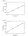
- the integrated COEL response from the 500 excitation pulses as a function of luminol concentration in the sample solutions are presented in Table 1 and Figure 2 .
- the background COEL response i.e., the response without the Al-conductor in the sample cell
- Sample solutions were prepared from the following components: 1.12 x 10 -1 M potassium dihydrogen phosphate and 8.80 x 10 -2 M dipotassium hydrogen phosphate buffer at pH 7.2, 1.0 x 10 -1 M tripropylamine, 7.1 x 10 -2 M sodium azide and varying amounts of tris(2,2'-bipyridyl)ruthenium(II) (Ru(b-py) 3 2+ ).
- the contactless electrogenerated luminescence (COEL) was initiated at the surface of a spherical 5.0-mm diameter gold conductor (Au-conductor) (i.e., a glass ball covered with a vacuum evaporated gold layer) as follows: excitation pulses of 0.4 ms duration and 6.0 V amplitude with the intermittent 10 ms zero level were applied to the current-delivering electrodes resulting in an approximately 50 mA peak current in the said sample solution. The resulting light emission (i.e., the COEL response) from the Au-conductor was detected by the photomultiplier.
- the integrated COEL response from the 500 excitation pulses as a function of Ru(bpy) 3 2+ concentration in the sample solution are presented in Table 2 and Figure 3 .
- the background COEL response (i.e., the response without the Au-conductor in the sample cell) was around 50 times lower than the analogous background COEL response in Table 2.
- Table 2 COEL response as a function of Ru(bpy) 3 2+ concentration [Ru(bpy) 3 2+ ]/mol 1 -1 COEL/au 0 853 1.0 x 10 -8 11025 1.0 x 10 -7 131540 1.0 x 10 -6 942059 1.0 x 10 -5 6715220
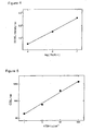
- Sample solutions were prepared from the following components: 5.0 x 10 -2 M borate buffer adjusted to pH 7.8, 7.1 x 10 -2 M sodium azide and varying amounts of Tb(III)-1 chelate where 1 is 2,6-bis[N,N-bis(carboxymethyl)aminomethyl]-4-benzoylphenol.
- COEL was initiated at the surface of a spherical 6.3-mm diameter Al-conductor (AbbotBall Company) as follows: excitation pulses of 0.4 ms; duration and 60 V amplitude with the intermittent 100 ms zero level were applied to the current-delivering electrodes resulting in an approximately 50 mA current in said sample solutions.
- the resulting light emission from the Alconductor was detected by the photomultiplier during the 0.08 - 8.0 ms interval from the end of the 0.4-ms excitation pulse (i.e., a delayed COEL or, abbreviated, a DCOEL response).
- the integrated DCOEL response from the 500 excitation pulses as a function of terbium(III) concentration in the sample solutions are presented in Table 3 and Figure 4 .
- the background DCOEL response i.e., the response without the Al-conductor in the sample cell
- a terbium(III) complex with 4-(3-isothiocyanatobenzoyl)-2,6-bis[N,-N-bis(carboxymethyl)aminomethyl]phenol was used as the labeling compound and was synthesized as set forth in J. Kankare et al., Anal. Chim. Acta, 266:205 (1992 ), which is incorporated herein by reference.
- the 6.3-mm diameter Al-conductors (AbbotBall Company) were coated with anti-hTSH IgG by a physical adsorption with 5.0 x 10 -2 M Tris-HCl buffer at pH 7.5, containing 9 g 1 -1 sodium chloride and 0.05 % sodium azide. The reaction mixture was left overnight at ambient temperature. After coating, the Al-conductors were washed with a solution containing 9 g 1 -1 sodium chloride, 0.01% sodium azide 0.2 g 1 -1 Tween, and saturated with 0.1 % BSA (bovine serum albumin) for overnight and stored wet at 4°C.
- BSA bovine serum albumin
- the coated and washed Al-conductor was placed in the aforementioned test tube. After one-hour incubation by continuously shaking, the Al-conductor was washed twice for 2 minutes with 400 ⁇ l 5.0 x 10 -2 M TRIS-HCl buffer at pH 7.4 containing additionally 0.05 % sodium azide, 0.2 % BSA, 0.1 % Tween. The Al-conductor was then transferred to the COEL cell containing 5.0 x 10 -2 M H 3 BO 3 -H 2 SO 4 buffer at pH 7.8 and 1.0 x 10 -2 M sodium azide. The DCOEL response was measured following the procedure of Example 3 and the results are presented in Table 4 and Figure 5 . Table 4 Immunoassay of hTSH by the contactless electrogenerated luminescence hTSH / ⁇ U ml -1 DCOEL/au 0 471 1 650 10 1070 100 4380 1000 13620
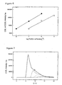
- Sample solutions were prepared from the following components: 5.0 x 10 -2 M borate buffer adjusted to pH 7.8, 3.0 x 10 -3 M peroxydisulfate and 1.0 x 10 -3 M Tween (polyoxyethylene(20) sorbitan monolaurate) and varying amounts of Ru(bpy) 3 2+ and Tb(III)-1 chelate.
- COEL was initiated at the surface of a spherical 6.3-mm diameter Al-conductor (AbbotBall Company) as follows: excitation pulses of 0.4 ms duration and 60 V amplitude with the intermittent 100 ms zero level were applied to the current-delivering electrodes resulting in an approximately 50 mA current in the said sample solution.
- the resulting light emission from the Al-conductor was detected by the photomultiplier during the excitation pulse (i.e., a COEL response) and during the 0.08 - 8.0 ms interval from the end of the 0.4-ms excitation pulse (i.e., a delayed COEL or DCOEL response).
- the integrated COEL and DCOEL responses from the 500 excitation pulses are presented in Table 5 and Figure 6 : the DCOEL response can be used for the quantification of Tb(III)-1 in these sample mixtures because the COEL of Ru(bpy) 3 2+ was too short-lived to reach the 0.08 - 8.0 ms detection window, while the listed COEL response (i.e., the observed COEL response subtracted by the COEL response of Tb(III)-1 which, in turn, is estimated from its measured DCOEL response) can be used for the quantification of Ru(bpy) 3 2+ .
- the listed COEL response i.e., the observed COEL response subtracted by the COEL response of Tb(III)-1 which, in turn, is estimated from its measured DCOEL response
- a sample solution was prepared from the following components: 1.12 x 10 -1 M potassium dihydrogen phosphate and 8.80 x 10 -2 M dipotassium hydrogen phosphate buffer at pH 7.2, 1.0 x 10 -1 M tripropylamine, 7.1 x 10 -2 M sodium azide and 1.0 x 10 -8 M tris(2,2'bipyridyl)ruthenium(II) (Ru(bpy) 3 2+ ).
- COEL was separately initiated at the surface of spherical gold conductors (Au-conductors) with the diameters listed in Table 6 (i.e., a glass ball covered with a vacuum evaporated gold layer) by applying a DC excitation voltage from 0 V to 20 V to the current-delivering electrodes at a sweep rate of 0.25 V s -1 in the sample solution.
- the resulting COEL responses of Ru(bpy) 3 2+ from the different Au-conductors was detected by the photomultiplier and are displayed in Figure 7 (2.0 mm (-.-), 2.5 mm (.......), 3.5 mm (---) and 6.0 mm (__)).
Claims (24)
- Verfahren zum Erzeugen einer Lumineszenz einer Lumineszenzverbindung zur quantitativen Bestimmung der Lumineszenzverbindung, das aufweist:Bereitstellen eines Elektrolyts, das darin aufweist: (i) ein Paar stromliefernder Elektroden, (ii) ein elektrisch leitfähiges Material, das zwischen den Elektroden angeordnet ist, jedoch nicht in elektronischem Kontakt mit den Elektroden steht, und (iii) die Lumineszenzverbindung, die sich in elektronischem Kontakt mit dem elektrisch leitfähigen Material befindet; undAnlegen eines elektrischen Stroms an die Elektroden, wodurch induziert wird, daß die Lumineszenzverbindung luminesziert.
- Verfahren nach Anspruch 1, wobei das Verfahren ferner das Messen der Lumineszenz aufweist, um die Konzentration der Lumineszenzverbindung quantitativ zu bestimmen.
- Verfahren nach Anspruch 1, wobei das elektrisch leitfähige Material ein elektrochemisch inertes Material ist.
- Verfahren nach Anspruch 3, wobei das elektrochemisch inerte Material aus Glaskohlenstoff, Gold, Platin oder Mischungen davon besteht.
- Verfahren nach Anspruch 1, wobei das elektrisch leitfähige Material ein isoliertes Metall oder Halbmetall ist.
- Verfahren nach Anspruch 5, wobei das isolierte Metall oder Halbmetall mit einem Oxid oder einem Polymerüberzug isoliert ist.
- Verfahren nach Anspruch 5, wobei das Metall oder Halbmetall aus Aluminium, Hafnium, Magnesium, Silizium, Tantal, Titan, Zirkon oder Mischungen davon besteht.
- Verfahren nach Anspruch 1, wobei das elektrisch leitfähige Material eine poröse Membran ist, die mit einer dünnen Schicht eines elektrochemisch inerten Materials oder eines isolierten Metalls oder Halbmetalls bedeckt ist.
- Verfahren nach Anspruch 1, wobei das elektrisch leitfähige Material aus einer Kombination eines elektrochemisch inerten Materials und eines isolierten Metalls oder Halbmetalls besteht.
- Verfahren nach Anspruch 1, wobei das elektrisch leitfähige Material ferner ein magnetisches Material aufweist.
- Verfahren nach Anspruch 1, wobei der Elektrolyt mindestens zwei elektrisch leitfähige Materialien enthält.
- Verfahren nach Anspruch 1, wobei der Elektrolyt mindestens zwei unterschiedliche Arten elektrisch leitfähiger Materialien enthält.
- Verfahren nach Anspruch 1, wobei der Elektrolyt ein wässeriger Elektrolyt ist.
- Verfahren nach Anspruch 1, wobei der Elektrolyt ein nichtwässeriger Elektrolyt ist.
- Verfahren nach Anspruch 1, wobei die Lumineszenzverbindung an der Oberfläche des elektrisch leitfähigen Materials befestigt ist.
- Verfahren nach Anspruch 1, wobei die Lumineszenzverbindung an einen interessierenden Analyt gebunden ist.
- Verfahren nach Anspruch 1, wobei die Lumineszenz nach einer Verzögerung nach dem Ende des Anlegens des elektrischen Stroms an die stromliefernden Elektroden gemessen wird.
- Verfahren nach Anspruch 16, wobei die Lumineszenz von mindestens zwei unterschiedlichen Lumineszenzverbindungen herrührt.
- Verfahren nach Anspruch 16, wobei die Lumineszenz an der Oberfläche mindestens zweier unterschiedlicher Arten von elektrisch leitfähigen Materialien gebildet wird.
- Verfahren nach Anspruch 19, wobei die Lumineszenz auf den Oberflächen der unterschiedlichen elektrisch leitfähigen Materialien bei unterschiedlichen Strompegeln angeregt und gemessen wird, die durch die stromliefernden Elektroden gehen.
- Verfahren nach Anspruch 18, wobei zur inneren Normierung Messungen zweier oder mehrerer Chemilumineszenzverbindungen an unterschiedlichen Leitern verwendet werden.
- Verfahren nach Anspruch 19, wobei zur Bestimmung der Konzentration zweier oder mehrerer Analyte Messungen zweier oder mehrerer Lumineszenzverbindungen an unterschiedlichen Leitern verwendet werden.
- Verfahren nach Anspruch 16, wobei das interessierende Analyt eine Nukleinsäuresequenz ist.
- Verfahren nach Anspruch 16, wobei das Analyt eine Aminosäuresequenz ist.
Applications Claiming Priority (3)
| Application Number | Priority Date | Filing Date | Title |
|---|---|---|---|
| US376139 | 1999-08-17 | ||
| US09/376,139 US6136268A (en) | 1999-08-17 | 1999-08-17 | Method for luminescence measurements |
| PCT/FI2000/000693 WO2001013095A1 (en) | 1999-08-17 | 2000-08-16 | Method for luminescence measurements |
Publications (2)
| Publication Number | Publication Date |
|---|---|
| EP1204858A2 EP1204858A2 (de) | 2002-05-15 |
| EP1204858B1 true EP1204858B1 (de) | 2008-05-07 |
Family
ID=23483870
Family Applications (1)
| Application Number | Title | Priority Date | Filing Date |
|---|---|---|---|
| EP00953206A Expired - Lifetime EP1204858B1 (de) | 1999-08-17 | 2000-08-16 | Verfahren für elektrolumineszenzmessungen |
Country Status (11)
| Country | Link |
|---|---|
| US (1) | US6136268A (de) |
| EP (1) | EP1204858B1 (de) |
| JP (1) | JP4573486B2 (de) |
| AT (1) | ATE394663T1 (de) |
| AU (1) | AU777936B2 (de) |
| CA (1) | CA2380655A1 (de) |
| DE (1) | DE60038803D1 (de) |
| DK (1) | DK1204858T3 (de) |
| ES (1) | ES2304971T3 (de) |
| PT (1) | PT1204858E (de) |
| WO (1) | WO2001013095A1 (de) |
Cited By (2)
| Publication number | Priority date | Publication date | Assignee | Title |
|---|---|---|---|---|
| US10159136B2 (en) | 2016-10-21 | 2018-12-18 | AhuraTech LLC | System and method for producing light in a liquid media |
| US10241111B2 (en) | 2016-10-21 | 2019-03-26 | AhuraTech LLC | Electroluminescent binding assays |
Families Citing this family (50)
| Publication number | Priority date | Publication date | Assignee | Title |
|---|---|---|---|---|
| US6200531B1 (en) * | 1998-05-11 | 2001-03-13 | Igen International, Inc. | Apparatus for carrying out electrochemiluminescence test measurements |
| US6347708B1 (en) * | 1999-03-22 | 2002-02-19 | Cedarapids Inc. | Wheel case for a vibratory apparatus |
| DK2420824T3 (en) | 2001-06-29 | 2019-03-25 | Meso Scale Technologies Llc | Multi-well plate with an array of wells and kit for use in performing an ECL assay |
| CA2353120A1 (en) * | 2001-07-16 | 2003-01-16 | Cardiogenics Inc. | Caged compound cleaving process |
| ATE471369T1 (de) | 2001-07-30 | 2010-07-15 | Meso Scale Technologies Llc | Assay-elektroden mit schichten aus immobilisiertem lipid/protein sowie verfahren zu deren herstellung und verwendung |
| US7063946B2 (en) | 2001-09-10 | 2006-06-20 | Meso Scale Technologies, Llc. | Methods, reagents, kits and apparatus for protein function analysis |
| US6919173B2 (en) * | 2001-09-10 | 2005-07-19 | Meso Scale Technologies, Llc. | Assay buffer, compositions containing the same, and methods of using the same |
| FI118611B (fi) * | 2002-04-15 | 2008-01-15 | Labmaster Oy | Eriste-elektrodilaitteet |
| WO2004001380A2 (en) * | 2002-06-20 | 2003-12-31 | Igen International, Inc | Electrochemiluminescence flow cell and flow cell components |
| AU2003256285A1 (en) * | 2002-06-28 | 2004-01-19 | Igen International, Inc. | Improved assay systems and components |
| AU2004209439B2 (en) * | 2003-01-31 | 2008-11-06 | Envirofuels L.P. | Method and composition for creation of conversion surface |
| WO2004113891A1 (en) * | 2003-06-13 | 2004-12-29 | Applera Corporation | Electrochemiluminescence electrode |
| US7238536B1 (en) * | 2004-03-22 | 2007-07-03 | Florida State University Research Foundation, Inc. | Controlled transport through multiple reversible interaction point membranes |
| US7796266B2 (en) | 2004-04-30 | 2010-09-14 | Kimberly-Clark Worldwide, Inc. | Optical detection system using electromagnetic radiation to detect presence or quantity of analyte |
| US7815854B2 (en) * | 2004-04-30 | 2010-10-19 | Kimberly-Clark Worldwide, Inc. | Electroluminescent illumination source for optical detection systems |
| JP5118964B2 (ja) | 2004-06-23 | 2013-01-16 | ボード・オブ・リージエンツ,ザ・ユニバーシテイ・オブ・テキサス・システム | 2粒子複合体を用いた生物学的分子の検出のための方法及び組成物 |
| FI119894B (fi) * | 2005-03-30 | 2009-04-30 | Labmaster Oy | Elektrokemiluminesenssiin perustuva analyysimenetelmä ja siinä käytettävä laite |
| ES2675044T3 (es) | 2005-06-03 | 2018-07-06 | Board Of Regents Of The University Of Texas System | Electroquímica y quimioluminiscencia electrogenerada con un único electrodo faradaico |
| US20070049693A1 (en) * | 2005-08-22 | 2007-03-01 | Envirofuels, Llc | Flow enhancement compositions for liquid and gases in tubes and pipes |
| WO2008061771A1 (en) * | 2006-11-23 | 2008-05-29 | Nanoident Technologies Ag | Device for optoelectronically characterizing samples |
| US20080263939A1 (en) * | 2006-12-08 | 2008-10-30 | Baxter C Edward | Lubricity improver compositions and methods for improving lubricity of hydrocarbon fuels |
| US8586378B2 (en) | 2008-04-11 | 2013-11-19 | Board Of Regents, The University Of Texas System | Method and apparatus for nanoparticle electrogenerated chemiluminescence amplification |
| ES2644997T3 (es) | 2008-05-08 | 2017-12-01 | Board Of Regents Of The University Of Texas System | Materiales nanoestructurados luminiscentes para su uso en quimioluminiscencia electrogenerada |
| US20100261292A1 (en) | 2009-04-10 | 2010-10-14 | Meso Scale Technologies, Llc | Methods for Conducting Assays |
| WO2011017094A2 (en) * | 2009-07-27 | 2011-02-10 | Ian Chamberlin | Assay apparatuses, consumables and methods |
| CN101957322B (zh) * | 2010-08-17 | 2012-01-11 | 中国科学院苏州纳米技术与纳米仿生研究所 | 一种用于电化学发光检测的流通池及其系统 |
| CA2814680C (en) | 2010-10-14 | 2021-11-16 | Meso Scale Technologies, Llc | Reagent storage in an assay device |
| CA2813089C (en) | 2010-10-25 | 2018-02-20 | F. Hoffmann-La Roche Ag | Use of signal enhancing compounds in electrochemiluminescence detection |
| US9777338B2 (en) | 2011-11-11 | 2017-10-03 | Meso Scale Technologies, Llc. | Co-binder assisted assay methods |
| DK2941633T3 (da) | 2013-01-04 | 2024-04-02 | Meso Scale Technologies Llc | Assayapparater, fremgangsmåder og reagenser |
| WO2014164594A1 (en) | 2013-03-11 | 2014-10-09 | Meso Scale Technologies, Llc. | Improved methods for conducting multiplexed assays |
| KR20220038550A (ko) | 2013-03-13 | 2022-03-28 | 메소 스케일 테크놀러지즈, 엘엘시 | 개선된 분석 방법 |
| US10114015B2 (en) | 2013-03-13 | 2018-10-30 | Meso Scale Technologies, Llc. | Assay methods |
| BR112015023775B1 (pt) | 2013-03-15 | 2022-08-16 | Lubrizol Advanced Materials, Inc | Composições de cpvc isentas de metal pesado |
| WO2015171971A1 (en) | 2014-05-09 | 2015-11-12 | Meso Scale Technologies, Llc. | Graphene-modified electrodes |
| KR20230022268A (ko) | 2014-05-15 | 2023-02-14 | 메소 스케일 테크놀러지즈, 엘엘시 | 개선된 분석 방법 |
| CN107003305B (zh) | 2014-12-08 | 2021-04-02 | 豪夫迈·罗氏有限公司 | 用于测量维生素d的方法 |
| CN108698047B (zh) | 2016-03-11 | 2022-04-01 | 豪夫迈·罗氏有限公司 | 电化学发光检测中的支链胺 |
| EP4310184A3 (de) | 2018-02-23 | 2024-05-01 | Meso Scale Technologies, LLC. | Verfahren zum screenen von antigen-bindenden molekülen durch normalisierung auf die konzentration eines antigen-bindenden moleküls |
| CN111351938A (zh) * | 2018-12-20 | 2020-06-30 | 麦德龙生物株式会社 | 电激发标记分子的方法和绝缘膜涂覆的电极 |
| JP2022515917A (ja) | 2019-01-03 | 2022-02-22 | メソ スケール テクノロジーズ エルエルシー | アッセイ測定を実行するための組成物および方法 |
| US20220099661A1 (en) | 2019-03-01 | 2022-03-31 | Meso Scale Technologies, Llc. | Electrochemiluminescent labeled probes for use in immunoassay methods, methods using such and kits comprising same |
| WO2020245377A1 (en) | 2019-06-07 | 2020-12-10 | F. Hoffmann-La Roche Ag | Hybridizing all-lna oligonucleotides |
| WO2021236584A1 (en) | 2020-05-19 | 2021-11-25 | Meso Scale Technologies, Llc. | Methods, compositions, and kits for nucleic acid detection |
| AU2021299536A1 (en) | 2020-07-01 | 2023-02-16 | Meso Scale Technologies, Llc. | Compositions and methods for assay measurements |
| EP4267961A1 (de) | 2020-12-22 | 2023-11-01 | F. Hoffmann-La Roche AG | Verfahren zum nachweis eines analyten von interesse in einer probe |
| IL309517A (en) | 2021-06-28 | 2024-02-01 | Meso Scale Technologies Llc | Methods, compounds and kits for amplifying test signals |
| US20230279290A1 (en) | 2021-12-30 | 2023-09-07 | Meso Scale Technologies, Llc. | Compositions and methods for assay measurements |
| WO2023156510A1 (en) | 2022-02-18 | 2023-08-24 | F. Hoffmann-La Roche Ag | Method for detecting an analyte of interest in a sample |
| WO2023196927A1 (en) | 2022-04-07 | 2023-10-12 | Meso Scale Technologies, Llc. | Methods and kits for assessing alzheimer's disease |
Family Cites Families (25)
| Publication number | Priority date | Publication date | Assignee | Title |
|---|---|---|---|---|
| US5238808A (en) * | 1984-10-31 | 1993-08-24 | Igen, Inc. | Luminescent metal chelate labels and means for detection |
| US5147806A (en) * | 1988-04-29 | 1992-09-15 | Igen, Inc. | Method and apparatus for conducting electrochemiluminescence measurements |
| SE461117B (sv) * | 1988-03-21 | 1990-01-08 | Jouko J Kankare | Foerfarande foer bestaemning av koncentrationen av en luminiscerande lantanid foerening |
| US5308754A (en) * | 1988-03-21 | 1994-05-03 | Kankare Jouko J | Electrogenerated luminescence in solution |
| WO1990005296A1 (en) * | 1988-11-03 | 1990-05-17 | Igen, Inc. | Electrochemiluminescent reaction utilizing amine-derived reductant |
| KR0143993B1 (ko) * | 1988-11-03 | 1998-07-15 | 리차아드 제이 매씨이 | 전기화학 발광성 분석 |
| US5779976A (en) * | 1988-11-03 | 1998-07-14 | Igen International, Inc. | Apparatus for improved luminescence assays |
| US5705402A (en) * | 1988-11-03 | 1998-01-06 | Igen International, Inc. | Method and apparatus for magnetic microparticulate based luminescence assay including plurality of magnets |
| US5746974A (en) * | 1988-11-03 | 1998-05-05 | Igen International, Inc. | Apparatus for improved luminescence assays using particle concentration, electrochemical generation of chemiluminescence and chemiluminescence detection |
| DE69125992T2 (de) * | 1990-09-14 | 1997-08-21 | Tosoh Corp | Verfahren und Kit für Immunoassay |
| IL100866A (en) * | 1991-02-06 | 1995-10-31 | Igen Inc | Luminescence test method and device based on magnetic tiny particles, containing many magnets |
| IL100867A (en) * | 1991-02-06 | 1995-12-08 | Igen Inc | Method and device for improved luminescence testing |
| JP3149255B2 (ja) * | 1991-02-19 | 2001-03-26 | ティーディーケイ株式会社 | 電気化学発光物質の分析方法及びそのための装置 |
| US5384265A (en) * | 1993-03-26 | 1995-01-24 | Geo-Centers, Inc. | Biomolecules bound to catalytic inorganic particles, immunoassays using the same |
| US5637508A (en) * | 1993-03-26 | 1997-06-10 | Geo-Centers, Inc. | Biomolecules bound to polymer or copolymer coated catalytic inorganic particles, immunoassays using the same and kits containing the same |
| DE4342942A1 (de) * | 1993-12-16 | 1995-06-22 | Boehringer Mannheim Gmbh | Vorrichtung und Verfahren zur Erzeugung optisch detektierbarer Signale durch Anlegen elektrischer Potentiale an Probeflüssigkeiten |
| US5744367A (en) * | 1994-11-10 | 1998-04-28 | Igen International, Inc. | Magnetic particle based electrochemiluminescent detection apparatus and method |
| US5527710A (en) * | 1994-12-02 | 1996-06-18 | Igen, Inc. | Rate measurements of biomolecular reactions using electrochemiluminescence |
| JPH08190801A (ja) * | 1995-01-12 | 1996-07-23 | Hitachi Ltd | 電気化学発光デバイス |
| US6207369B1 (en) * | 1995-03-10 | 2001-03-27 | Meso Scale Technologies, Llc | Multi-array, multi-specific electrochemiluminescence testing |
| HUP9801679A3 (en) * | 1995-03-10 | 2001-01-29 | Meso Scale Technologies Llc Co | Process and agent for multi-array, multi-specific electrochemiluminescence testing |
| AU6476696A (en) * | 1995-06-07 | 1996-12-30 | Igen, Inc. | Simultaneous assay method using lanthanide chelates as the l uminophore for multiple labels |
| US5744376A (en) * | 1996-04-08 | 1998-04-28 | Chartered Semiconductor Manufacturing Pte, Ltd | Method of manufacturing copper interconnect with top barrier layer |
| FI970593A (fi) * | 1997-02-12 | 1998-08-13 | Sakari Mikael Kulmala | Pinnoitettujen johteiden käyttö analyyttisiin tarkoituksiin |
| EP0962773A1 (de) * | 1998-06-03 | 1999-12-08 | Mark Howard Jones | Prüfverfahren, Vorrichtung und Markierungsmittel basierend auf Elektrochemie |
-
1999
- 1999-08-17 US US09/376,139 patent/US6136268A/en not_active Expired - Fee Related
-
2000
- 2000-08-16 DE DE60038803T patent/DE60038803D1/de not_active Expired - Lifetime
- 2000-08-16 AU AU65737/00A patent/AU777936B2/en not_active Ceased
- 2000-08-16 PT PT00953206T patent/PT1204858E/pt unknown
- 2000-08-16 JP JP2001517146A patent/JP4573486B2/ja not_active Expired - Fee Related
- 2000-08-16 DK DK00953206T patent/DK1204858T3/da active
- 2000-08-16 WO PCT/FI2000/000693 patent/WO2001013095A1/en active IP Right Grant
- 2000-08-16 EP EP00953206A patent/EP1204858B1/de not_active Expired - Lifetime
- 2000-08-16 CA CA002380655A patent/CA2380655A1/en not_active Abandoned
- 2000-08-16 ES ES00953206T patent/ES2304971T3/es not_active Expired - Lifetime
- 2000-08-16 AT AT00953206T patent/ATE394663T1/de active
Cited By (2)
| Publication number | Priority date | Publication date | Assignee | Title |
|---|---|---|---|---|
| US10159136B2 (en) | 2016-10-21 | 2018-12-18 | AhuraTech LLC | System and method for producing light in a liquid media |
| US10241111B2 (en) | 2016-10-21 | 2019-03-26 | AhuraTech LLC | Electroluminescent binding assays |
Also Published As
| Publication number | Publication date |
|---|---|
| EP1204858A2 (de) | 2002-05-15 |
| ES2304971T3 (es) | 2008-11-01 |
| ATE394663T1 (de) | 2008-05-15 |
| PT1204858E (pt) | 2008-08-07 |
| WO2001013095A1 (en) | 2001-02-22 |
| AU777936B2 (en) | 2004-11-04 |
| WO2001013095A8 (en) | 2001-06-21 |
| DE60038803D1 (de) | 2008-06-19 |
| JP4573486B2 (ja) | 2010-11-04 |
| JP2003507704A (ja) | 2003-02-25 |
| DK1204858T3 (da) | 2008-08-11 |
| AU6573700A (en) | 2001-03-13 |
| US6136268A (en) | 2000-10-24 |
| CA2380655A1 (en) | 2001-02-22 |
Similar Documents
| Publication | Publication Date | Title |
|---|---|---|
| EP1204858B1 (de) | Verfahren für elektrolumineszenzmessungen | |
| Knight et al. | Occurrence, mechanisms and analytical applications of electrogenerated chemiluminescence. A review | |
| US5308754A (en) | Electrogenerated luminescence in solution | |
| Knight | A review of recent trends in analytical applications of electrogenerated chemiluminescence | |
| US5746974A (en) | Apparatus for improved luminescence assays using particle concentration, electrochemical generation of chemiluminescence and chemiluminescence detection | |
| CA2112675C (en) | Methods and apparatus for improved luminescence assays using particle concentration and chemiluminescence detection | |
| US6251690B1 (en) | Electrical excitation of label substances at insulating film-coated conductors | |
| CA2713949C (en) | Method and apparatus for nanoparticle electrogenerated chemiluminescence amplification | |
| Namba et al. | Highly sensitive electrochemiluminescence immunoassay using the ruthenium chelate-labeled antibody bound on the magnetic micro beads | |
| US6599473B1 (en) | Electrochemilumiscence method for detecting analytes | |
| CA2002083C (en) | Enhanced electrochemiluminescence | |
| Kulmala et al. | Heterogeneous and homogeneous electrochemiluminoimmunoassays of hTSH at disposable oxide-covered aluminum electrodes | |
| US5538687A (en) | Apparatus for generating optically detectable signals by applying electrical potentials to sample liquids | |
| US7494819B2 (en) | Electrochemiluminescence electrode | |
| GB2217007A (en) | Electrochemical analysis of analytes in solution | |
| AU619842B2 (en) | Apparatus for conducting a plurality of simultaneous measurements of electrochemiluminescent phenomena | |
| Suomi et al. | Hot electron-induced electrogenerated chemiluminescence | |
| Li et al. | Ultrasensitive eletrogenerated chemiluminescence immunoassay by magnetic nanobead amplification | |
| JPH11352064A (ja) | 電気化学発光分析装置 | |
| JP4301595B2 (ja) | 電気化学発光分析装置 | |
| FI111758B (fi) | Lyoluminesenssin käyttö analyyttisiin tarkoituksiin | |
| US20060246603A1 (en) | Generation of chemiluminescence by hydrogen | |
| FI111663B (fi) | Elektrokemiluminesenssin aikaerotteisen mittaustavan käyttö analyyttisiin tarkoituksiin | |
| Miao et al. | Electrogenerated Chemiluminescence (ECL) |
Legal Events
| Date | Code | Title | Description |
|---|---|---|---|
| PUAI | Public reference made under article 153(3) epc to a published international application that has entered the european phase |
Free format text: ORIGINAL CODE: 0009012 |
|
| 17P | Request for examination filed |
Effective date: 20020208 |
|
| AK | Designated contracting states |
Kind code of ref document: A2 Designated state(s): AT BE CH CY DE DK ES FI FR GB GR IE IT LI LU MC NL PT |
|
| AX | Request for extension of the european patent |
Free format text: AL;LT;LV;MK;RO;SI |
|
| RIN1 | Information on inventor provided before grant (corrected) |
Inventor name: KANKARE, JOUKO Inventor name: NAUMA, MAURI Inventor name: JUHALA, PENTTI Inventor name: KAEPPI, RAINER Inventor name: LOIKAS, KARI Inventor name: KULMALA, SAKARI Inventor name: HAAPAKKA, KEIJO Inventor name: ALA-KLEME, TIMO |
|
| RAP1 | Party data changed (applicant data changed or rights of an application transferred) |
Owner name: ORION DIAGNOSTICA OY |
|
| GRAP | Despatch of communication of intention to grant a patent |
Free format text: ORIGINAL CODE: EPIDOSNIGR1 |
|
| RIC1 | Information provided on ipc code assigned before grant |
Ipc: G01N 21/69 20060101AFI20071114BHEP |
|
| RTI1 | Title (correction) |
Free format text: METHOD FOR ELECTROLUMINESCENCE MEASUREMENTS |
|
| RBV | Designated contracting states (corrected) |
Designated state(s): AT BE CH CY DE DK ES FI FR GB GR IE IT LI LU MC NL PT SE |
|
| GRAS | Grant fee paid |
Free format text: ORIGINAL CODE: EPIDOSNIGR3 |
|
| GRAA | (expected) grant |
Free format text: ORIGINAL CODE: 0009210 |
|
| AK | Designated contracting states |
Kind code of ref document: B1 Designated state(s): AT BE CH CY DE DK ES FI FR GB GR IE IT LI LU MC NL PT SE |
|
| REG | Reference to a national code |
Ref country code: GB Ref legal event code: FG4D |
|
| RIN1 | Information on inventor provided before grant (corrected) |
Inventor name: LOIKAS, KARI Inventor name: KANKARE, JOUKO Inventor name: VALLI, RAILI Inventor name: JUHALA, PENTTI Inventor name: KULMALA, SAKARI Inventor name: KAEPPI, RAINER Inventor name: ALA-KLEME, TIMO Inventor name: HAAPAKKA, KEIJO Inventor name: PIHLAJA, JYRKI Inventor name: SUTELA, TIMO Inventor name: NAUMA, MAURI |
|
| REG | Reference to a national code |
Ref country code: CH Ref legal event code: EP |
|
| REG | Reference to a national code |
Ref country code: IE Ref legal event code: FG4D Free format text: LANGUAGE OF EP DOCUMENT: FRENCH |
|
| REF | Corresponds to: |
Ref document number: 60038803 Country of ref document: DE Date of ref document: 20080619 Kind code of ref document: P |
|
| REG | Reference to a national code |
Ref country code: CH Ref legal event code: NV Representative=s name: BOVARD AG PATENTANWAELTE |
|
| REG | Reference to a national code |
Ref country code: PT Ref legal event code: SC4A Free format text: AVAILABILITY OF NATIONAL TRANSLATION Effective date: 20080729 |
|
| REG | Reference to a national code |
Ref country code: DK Ref legal event code: T3 |
|
| REG | Reference to a national code |
Ref country code: SE Ref legal event code: TRGR |
|
| REG | Reference to a national code |
Ref country code: ES Ref legal event code: FG2A Ref document number: 2304971 Country of ref document: ES Kind code of ref document: T3 |
|
| PLBE | No opposition filed within time limit |
Free format text: ORIGINAL CODE: 0009261 |
|
| STAA | Information on the status of an ep patent application or granted ep patent |
Free format text: STATUS: NO OPPOSITION FILED WITHIN TIME LIMIT |
|
| PG25 | Lapsed in a contracting state [announced via postgrant information from national office to epo] |
Ref country code: MC Free format text: LAPSE BECAUSE OF NON-PAYMENT OF DUE FEES Effective date: 20080831 |
|
| 26N | No opposition filed |
Effective date: 20090210 |
|
| REG | Reference to a national code |
Ref country code: IE Ref legal event code: MM4A |
|
| PG25 | Lapsed in a contracting state [announced via postgrant information from national office to epo] |
Ref country code: IE Free format text: LAPSE BECAUSE OF NON-PAYMENT OF DUE FEES Effective date: 20080816 |
|
| PG25 | Lapsed in a contracting state [announced via postgrant information from national office to epo] |
Ref country code: CY Free format text: LAPSE BECAUSE OF FAILURE TO SUBMIT A TRANSLATION OF THE DESCRIPTION OR TO PAY THE FEE WITHIN THE PRESCRIBED TIME-LIMIT Effective date: 20080507 |
|
| PG25 | Lapsed in a contracting state [announced via postgrant information from national office to epo] |
Ref country code: GR Free format text: LAPSE BECAUSE OF FAILURE TO SUBMIT A TRANSLATION OF THE DESCRIPTION OR TO PAY THE FEE WITHIN THE PRESCRIBED TIME-LIMIT Effective date: 20080808 |
|
| REG | Reference to a national code |
Ref country code: CH Ref legal event code: PFA Owner name: ORION DIAGNOSTICA OY Free format text: ORION DIAGNOSTICA OY#KOIVU-MANKKAAN TIE 6 B#02200 ESPOO (FI) -TRANSFER TO- ORION DIAGNOSTICA OY#KOIVU-MANKKAAN TIE 6 B#02200 ESPOO (FI) |
|
| PGFP | Annual fee paid to national office [announced via postgrant information from national office to epo] |
Ref country code: CH Payment date: 20110824 Year of fee payment: 12 |
|
| PGFP | Annual fee paid to national office [announced via postgrant information from national office to epo] |
Ref country code: LU Payment date: 20120824 Year of fee payment: 13 |
|
| PGFP | Annual fee paid to national office [announced via postgrant information from national office to epo] |
Ref country code: ES Payment date: 20120816 Year of fee payment: 13 Ref country code: BE Payment date: 20120824 Year of fee payment: 13 Ref country code: IT Payment date: 20120823 Year of fee payment: 13 |
|
| PGFP | Annual fee paid to national office [announced via postgrant information from national office to epo] |
Ref country code: PT Payment date: 20120216 Year of fee payment: 13 Ref country code: NL Payment date: 20120821 Year of fee payment: 13 |
|
| PGFP | Annual fee paid to national office [announced via postgrant information from national office to epo] |
Ref country code: AT Payment date: 20120813 Year of fee payment: 13 |
|
| REG | Reference to a national code |
Ref country code: PT Ref legal event code: MM4A Free format text: LAPSE DUE TO NON-PAYMENT OF FEES Effective date: 20140217 |
|
| BERE | Be: lapsed |
Owner name: ORION DIAGNOSTICA OY Effective date: 20130831 |
|
| REG | Reference to a national code |
Ref country code: NL Ref legal event code: V1 Effective date: 20140301 |
|
| REG | Reference to a national code |
Ref country code: CH Ref legal event code: PL |
|
| REG | Reference to a national code |
Ref country code: AT Ref legal event code: MM01 Ref document number: 394663 Country of ref document: AT Kind code of ref document: T Effective date: 20130816 |
|
| PG25 | Lapsed in a contracting state [announced via postgrant information from national office to epo] |
Ref country code: LI Free format text: LAPSE BECAUSE OF NON-PAYMENT OF DUE FEES Effective date: 20130831 Ref country code: CH Free format text: LAPSE BECAUSE OF NON-PAYMENT OF DUE FEES Effective date: 20130831 Ref country code: NL Free format text: LAPSE BECAUSE OF NON-PAYMENT OF DUE FEES Effective date: 20140301 |
|
| PG25 | Lapsed in a contracting state [announced via postgrant information from national office to epo] |
Ref country code: BE Free format text: LAPSE BECAUSE OF NON-PAYMENT OF DUE FEES Effective date: 20130831 Ref country code: AT Free format text: LAPSE BECAUSE OF NON-PAYMENT OF DUE FEES Effective date: 20130816 Ref country code: IT Free format text: LAPSE BECAUSE OF NON-PAYMENT OF DUE FEES Effective date: 20130816 |
|
| PG25 | Lapsed in a contracting state [announced via postgrant information from national office to epo] |
Ref country code: PT Free format text: LAPSE BECAUSE OF NON-PAYMENT OF DUE FEES Effective date: 20140217 |
|
| REG | Reference to a national code |
Ref country code: ES Ref legal event code: FD2A Effective date: 20141013 |
|
| PG25 | Lapsed in a contracting state [announced via postgrant information from national office to epo] |
Ref country code: ES Free format text: LAPSE BECAUSE OF NON-PAYMENT OF DUE FEES Effective date: 20130817 |
|
| PG25 | Lapsed in a contracting state [announced via postgrant information from national office to epo] |
Ref country code: LU Free format text: LAPSE BECAUSE OF NON-PAYMENT OF DUE FEES Effective date: 20130816 |
|
| REG | Reference to a national code |
Ref country code: FR Ref legal event code: PLFP Year of fee payment: 17 |
|
| REG | Reference to a national code |
Ref country code: FR Ref legal event code: PLFP Year of fee payment: 18 |
|
| REG | Reference to a national code |
Ref country code: FR Ref legal event code: PLFP Year of fee payment: 19 |
|
| PGFP | Annual fee paid to national office [announced via postgrant information from national office to epo] |
Ref country code: FR Payment date: 20180827 Year of fee payment: 19 Ref country code: DE Payment date: 20180823 Year of fee payment: 19 |
|
| PGFP | Annual fee paid to national office [announced via postgrant information from national office to epo] |
Ref country code: DK Payment date: 20180823 Year of fee payment: 19 Ref country code: GB Payment date: 20180822 Year of fee payment: 19 Ref country code: SE Payment date: 20180823 Year of fee payment: 19 Ref country code: FI Payment date: 20180822 Year of fee payment: 19 |
|
| REG | Reference to a national code |
Ref country code: DE Ref legal event code: R119 Ref document number: 60038803 Country of ref document: DE |
|
| REG | Reference to a national code |
Ref country code: FI Ref legal event code: MAE |
|
| REG | Reference to a national code |
Ref country code: DK Ref legal event code: EBP Effective date: 20190831 |
|
| REG | Reference to a national code |
Ref country code: SE Ref legal event code: EUG |
|
| GBPC | Gb: european patent ceased through non-payment of renewal fee |
Effective date: 20190816 |
|
| PG25 | Lapsed in a contracting state [announced via postgrant information from national office to epo] |
Ref country code: SE Free format text: LAPSE BECAUSE OF NON-PAYMENT OF DUE FEES Effective date: 20190817 Ref country code: FI Free format text: LAPSE BECAUSE OF NON-PAYMENT OF DUE FEES Effective date: 20190816 |
|
| PG25 | Lapsed in a contracting state [announced via postgrant information from national office to epo] |
Ref country code: DE Free format text: LAPSE BECAUSE OF NON-PAYMENT OF DUE FEES Effective date: 20200303 Ref country code: FR Free format text: LAPSE BECAUSE OF NON-PAYMENT OF DUE FEES Effective date: 20190831 Ref country code: DK Free format text: LAPSE BECAUSE OF NON-PAYMENT OF DUE FEES Effective date: 20190831 |
|
| PG25 | Lapsed in a contracting state [announced via postgrant information from national office to epo] |
Ref country code: GB Free format text: LAPSE BECAUSE OF NON-PAYMENT OF DUE FEES Effective date: 20190816 |