EP1204220B1 - Procédé pour l'acquisition d'une fonction de gain d'émission - Google Patents
Procédé pour l'acquisition d'une fonction de gain d'émission Download PDFInfo
- Publication number
- EP1204220B1 EP1204220B1 EP01402661A EP01402661A EP1204220B1 EP 1204220 B1 EP1204220 B1 EP 1204220B1 EP 01402661 A EP01402661 A EP 01402661A EP 01402661 A EP01402661 A EP 01402661A EP 1204220 B1 EP1204220 B1 EP 1204220B1
- Authority
- EP
- European Patent Office
- Prior art keywords
- noise
- power
- array
- transmission
- matrix
- Prior art date
- Legal status (The legal status is an assumption and is not a legal conclusion. Google has not performed a legal analysis and makes no representation as to the accuracy of the status listed.)
- Expired - Lifetime
Links
Images


Classifications
-
- H—ELECTRICITY
- H04—ELECTRIC COMMUNICATION TECHNIQUE
- H04B—TRANSMISSION
- H04B7/00—Radio transmission systems, i.e. using radiation field
- H04B7/02—Diversity systems; Multi-antenna system, i.e. transmission or reception using multiple antennas
- H04B7/04—Diversity systems; Multi-antenna system, i.e. transmission or reception using multiple antennas using two or more spaced independent antennas
- H04B7/06—Diversity systems; Multi-antenna system, i.e. transmission or reception using multiple antennas using two or more spaced independent antennas at the transmitting station
- H04B7/0613—Diversity systems; Multi-antenna system, i.e. transmission or reception using multiple antennas using two or more spaced independent antennas at the transmitting station using simultaneous transmission
- H04B7/0615—Diversity systems; Multi-antenna system, i.e. transmission or reception using multiple antennas using two or more spaced independent antennas at the transmitting station using simultaneous transmission of weighted versions of same signal
- H04B7/0619—Diversity systems; Multi-antenna system, i.e. transmission or reception using multiple antennas using two or more spaced independent antennas at the transmitting station using simultaneous transmission of weighted versions of same signal using feedback from receiving side
-
- H—ELECTRICITY
- H04—ELECTRIC COMMUNICATION TECHNIQUE
- H04B—TRANSMISSION
- H04B7/00—Radio transmission systems, i.e. using radiation field
- H04B7/02—Diversity systems; Multi-antenna system, i.e. transmission or reception using multiple antennas
- H04B7/04—Diversity systems; Multi-antenna system, i.e. transmission or reception using multiple antennas using two or more spaced independent antennas
- H04B7/06—Diversity systems; Multi-antenna system, i.e. transmission or reception using multiple antennas using two or more spaced independent antennas at the transmitting station
- H04B7/0613—Diversity systems; Multi-antenna system, i.e. transmission or reception using multiple antennas using two or more spaced independent antennas at the transmitting station using simultaneous transmission
- H04B7/0615—Diversity systems; Multi-antenna system, i.e. transmission or reception using multiple antennas using two or more spaced independent antennas at the transmitting station using simultaneous transmission of weighted versions of same signal
Definitions
- the present invention concerns in general terms a method for obtaining a gain function in transmission mode. More particularly, the present invention relates to a method for obtaining an antenna gain in transmission mode for a base station in a mobile telecommunication system. It makes it possible to obtain an antenna gain in transmission mode from an antenna gain in reception mode.
- each uses an array of antennae, generally linear and uniform (that is to say with a constant pitch) and a signal weighting module. More precisely, if it is wished to form a beam in reception mode, the signals received by the different antennae are weighted by a set of complex coefficients before being added. Conversely, if it is wished to form a channel in transmission mode, the signal to be transmitted is weighted by a set of complex coefficients and the signals thus obtained are transmitted by the different antennae.
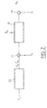
- Fig. 1 illustrates a known device for obtaining an antenna gain in transmission and reception.
- the device comprises an array of antennae (10 0 ),(10 1 ),...,(10 N-1 ), a transmission weighting module (11) and a reception weighting module (15).
- ⁇ i is the angle between a reference axis and the normal to the antenna of index i
- R the radius of curvature of the array
- ⁇ is the angular difference between two consecutive antennae in the array.
- the complex gain (or the complex gain function) in transmission can be written: with the same conventions as those adopted above and where e d ⁇ is the vector x corresponding to a plane wave transmitted in the direction ⁇ .
- the weighting vectors in reception and transmission mode will be called respectively b u and b d .
- the array of antennae of a base station receives signals transmitted by a plurality of mobile terminals.
- the signals transmitted by the different mobile terminals are separated by means of the use of orthogonal codes on transmission and filters adapted to these codes on reception. In practice, however, the separation of the different signals received is not perfect.
- the criterion to be maximised is then the ratio of signal to noise plus interference, the latter being due to the signals transmitted by the other mobile terminals.
- the downlink between a base station and a given mobile terminal is disturbed not only by the background noise but by the interference due to the signals transmitted by the said base station to other mobile terminals.
- optimise the weighting vector in reception mode, b u by estimating the uplink channel and the density of interference at the base station, it is quite different with regard to the optimisation of the weighting vector in transmission mode, b d .
- EP0999658 discloses a method for beamforming in a mobile telecommunications system, where in order to maximize the SNR, the downlink weighting vector employed by the base station is determined using information supplied by the wireless terminal.
- the aim of the invention is to propose a method for determining the transmission weighting vector, b d , optimising the ratio of signal to noise plus interference on the downlink and requiring the transmission only of a small quantity of information on the uplink.
- the invention is defined by a method for obtaining a transmission gain function by means of an array of antennae and a weighting of the signals received or to be transmitted by vectors ( b ) of N complex coefficients, referred to as weighting vectors, N being the number of antennae in the array, the array transmitting to a telecommunication terminal on a transmission channel, referred to as the downlink channel, a downlink transmission signal (S d ) and the said terminal transmitting to the said array on a transmission channel, referred to as the uplink channel, an uplink transmission signal (S u ), the said uplink channel being disturbed by a first isotropic noise (N) and/or a first directional noise, referred to as the uplink interference (I u ), the said downlink channel being disturbed by a second isotropic noise (N') and/or a second directional noise, referred to as the downlink interference (I d ).
- D u first noise matrix
- D d second noise matrix
- the first weighting vector ( b u ) is obtained for a first working frequency ( ⁇ u ) of the array and the second weighting vector ( b d ) is obtained for a second working frequency ( ⁇ d ) of the array.
- H u is the transformation matrix at the frequency ( f u )
- H + d is the pseudo-inverse matrix of the matrix H d
- D u is the first noise matrix
- D d is the second noise matrix
- the array transmits on a plurality of downlink channels a plurality of transmission signals to a plurality of telecommunication terminals and receives from them a plurality of transmission signals transmitted on a plurality of uplink channels and if each downlink channel j relating to a terminal j of the said plurality is associated with a second weighting vector b d ( j ), the second noise matrix relating to the downlink channel j is a diagonal matrix of size MxM and of components ⁇ 2 dk ( j )+ ⁇ d ( j ).
- N ' 0 / I d ( j ) where ⁇ 2 / dk ( j ) is the power of the downlink interference for the downlink channel in the direction k, ⁇ d ( j ) is a coefficient characterising the power transfer on the downlink channel j, N' 0 is the power of the second isotropic noise, and I d is the total power of the downlink interference.
- the said coefficient ⁇ d (j) is estimated from a coefficient characterising the orthogonality of the uplink channel j .
- the coefficient ⁇ d ( j ) can be transmitted to the array by the terminal j on the associated uplink channel.
- the invention is also defined by a device adapted to implement the method which has just been disclosed.
- a first general idea at the basis of the invention is to sample the transmission and reception gain functions in order to construct transmission and reception gain vectors.
- optimum weighting vectors in terms of ratio of signal to noise plus interference, can then be obtained from transmission and reception gain vectors according to matrix equations.
- a second general idea at the basis of the invention is to obtain a transmission weighting vector, optimum in terms of ratio of signal to noise plus interference obtained, from the reception gain weighting vector assumed itself to be optimum.
- weighting vectors can be obtained from a series of samples of the corresponding gain function.
- G( ⁇ ) be the antenna gain function obtained by means of a weighting vector b .
- the image of C N by h f s is a vector sub-space of C M with a dimension at most equal to N , which will be denoted Im f . If a base of C N is chosen, for example the canonical base, and a base of C M , it is possible to express the linear application h f s by a matrix H f of size MxN which is at most of rank N.
- G be any gain vector corresponding to a sampled gain function.
- H + / f (H * T / f .H f ) -1 .H *T / f is the pseudo-inverse matrix of the matrix H f with H *T / f a conjugate transpose of the matrix H f .
- the vectors e k are the weighting vectors of the array making it possible to form beams in the directions ⁇ k .
- H' f H f .T -1
- This equation makes it possible in particular to obtain, at a second working frequency, a sampled gain diagram which is as close as possible to the one, referred to as the reference, obtained at a first working frequency.
- Equation (10) applies advantageously to the array of antennae of a base station in a mobile telecommunication system operating in FDD (Frequency Division Duplex) mode.
- a frequency f d is used on the downlinks and a frequency f u distinct from f d is used on the uplinks.
- Equation (11) makes it possible, as has been seen, to obtain, at the transmission frequency f u , a sampled gain diagram which is as close as possible to a reference diagram obtained at the reception frequency f d .
- the interference profile that is to say the angular distribution of the power of the interference, is not necessarily the same on the downlink channel as on the uplink channel. This is because the directions of the interfering sources are not necessarily identical in transmission and reception. Consequently, though the reception gain diagram is optimum for a reception interference profile, it will not necessarily be so for a transmission interference profile. As will be shown later, if the transmission and reception interference profiles differ, equation (11) must be modified in order to take account of this difference.
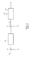
- Fig. 2 depicts the assembly consisting of the uplink channel (20), the array of antennae (22) and the reception weighting module (23).
- the effect of the noise has been represented by the addition (21) of a directional noise I u due to the interfering signals, and at (24) an isotropic centred white Gaussian background noise N.
- Fig. 3 depicts the assembly consisting of the downlink channel (30), the array of antennae (32) and the transmission weighting module (33).
- the effect of the noise has been represented by the addition at (31) of a directional noise I d due to the interfering signals and at (34) by a centred isotropic white Gaussian background noise N'.
- This vector has P ' from amongst M non-zero coefficients, where P' is the number of propagation paths of the channel.
- the matrix D u can be estimated at the base station from a measurement of the noise power and the interference in the directions ⁇ k .
- the matrix D d cannot be estimated as simply.
- the matrix D u can be estimated at the base station from a measurement of the noise power and the interference in the directions ⁇ k , for example during a period of silence of the mobile terminal.
- the matrix D d cannot be estimated as simply.
- the value of ⁇ can then be estimated directly by the base station, for example at the power control loop.
- the interference power attributable to the mobile terminals TS j in the direction ⁇ k can be written: where the indices between parentheses have been added so as to distinguish the quantities relating to the different downlink channels (that is to say intended for the different mobile terminals) and where:
- the coefficient of orthogonality of the downlink channel, ⁇ d (j 0 ) is little different from that of the uplink channel, ⁇ u (j 0 ) , the above three quantities arc available at the base station without a return of information by the mobile terminal being necessary.
- the power transfer coefficient, ⁇ d (j 0 ) is transmitted to the base station on the uplink channel from TS j0 or directly estimated by the latter. It is therefore possible to obtain the matrix D d for a slight additional cost in terms of conveyance resources.
- Fig. 4 illustrates an example of a device according to one embodiment of the invention. For reasons of simplicity, the processing of a single communication with a mobile terminal has been depicted.
- the device installed at the base station, comprises an array of antennae (40 0 ),(40 1 ),..(40 N-1 ) coupled by means of duplexers to a first reception weighting module (45), weighting the signals received by the different antennae by means of a first weighting vector, b u , and to a second transmission weighting module (41), weighting a signal to be transmitted by a second weighting vector, b d .
- the N outputs of antennae are directed to a module (46) estimating, in a manner known per se, the optimum weighting vector b u .
- Estimators of the noise power matrices (43) and (44) estimate respectively the matrices D u 2 and D d 2 .
- the matrices D u 2 and D d 2 are supplied to a matrix calculation module (42) which calculates the vector b d from the vector b u according to equation (22).
- the vector b d is then transmitted to the weighting module (41).
- the matrix D d 2 is evaluated in (44) by means of equation (23).
- the estimation module (44) receives an estimation of the coupling coefficient, ⁇ d or ⁇ according to circumstances, as well as interference powers ⁇ 2 / dk in the directions ⁇ k and the total power I d .
- the values ⁇ 2 / dk are advantageously calculated from equation (24) using the values of the transmission signals, S d (j), j ⁇ j0 , intended for the mobile terminals other than the one in question ( j 0 ) and the gain vectors, G d ( j ), j ⁇ j 0 , which are associated with them.
Claims (10)
- Méthode d'obtention d'une fonction de gain de transmission au moyen d'un réseau d'antennes, les signaux reçus ou à transmettre étant pondérés par des vecteurs (
b ) de N coefficients complexes, appelés vecteurs de pondération, N étant le nombre d'antennes dans le réseau, le réseau transmettant, à un terminal de télécommunication sur une voie de transmission, appelée voie de liaison descendante, un signal de transmission de liaison descendante (Sd) et ledit terminal transmettant audit réseau sur une voie de transmission, appelée voie de liaison montante, un signal de transmission de liaison montante (Su), ladite voie de liaison montante étant perturbée par un premier bruit isotrope (N) et/ou un premier bruit directif, appelé l'interférence de liaison montante (Iu), ladite voie de liaison descendante étant perturbée par un deuxième bruit isotrope (N') et/ou un deuxième bruit directif, appelé l'interférence de liaison descendante (Id), caractérisée en ce qu'un premier vecteur de pondération (b u ) ayant été déterminé afin de maximiser, en cours de réception par le réseau, le rapport ((C/I+N)u) du signal reçu venant dudit terminal sur le bruit plus l'interférence perturbant ladite voie de liaison montante, un deuxième vecteur de pondération (b d ) maximisant, en cours de réception par le terminal, le rapport ((C/I+N)d) du signal reçu venant du réseau sur le bruit plus l'interférence perturbant la voie de liaison descendante, est calculé à partir dudit premier vecteur de pondération sous la forme d'un produit matriciel comprenant une première matrice de bruit (Du) qui est une fonction de la puissance du premier bruit isotrope et/ou de la puissance du premier bruit directif et une deuxième matrice de bruit (Dd) qui est une fonction de la puissance du deuxième bruit isotrope et/ou de la puissance du deuxième bruit directif. - Méthode d'obtention d'une fonction de gain de transmission selon la revendication 1, caractérisée en ce que le premier vecteur de pondération (
b u ) est obtenu pour une première fréquence de travail (fu) du réseau et le deuxième vecteur de pondération (b d ) est obtenu pour une deuxième fréquence de travail (fd) du réseau. - Méthode d'obtention d'une fonction de gain de transmission selon la revendication 2, caractérisée en ce que, une fonction de gain étant représentée par un vecteur, appelé vecteur de gain (
G ), de M échantillons complexes de ladite fonction de gain prise dans M directions distinctes (k), ledit vecteur de gain étant exprimé par le produit d'un vecteur de pondération (b ) et d'une matrice de transformation dépendant de la fréquence de travail du réseau, le deuxième vecteur de pondérationb d est obtenu à partir du premier vecteur de pondérationb u par : - Méthode d'obtention dune fonction de gain de transmission selon la revendication 3, caractérisée en ce que la première matrice de bruit est une matrice diagonale de taille MxM et de composantes
G u=Hub u. - Méthode d'obtention d'une fonction de gain de transmission selon la revendication 3 ou 4, caractérisée en ce que la deuxième matrice de bruit est une matrice diagonale de taille MxM et de composantes
C d est un vecteur se composant des échantillons de la fonction de la fonction de transfert de la voie de liaison descendante pris dans lesdites M directions et Id est la puissance totale de l'interférence de liaison descendante. - Méthode d'obtention dune fonction de gain de transmission selon la revendication 3 ou 4, caractérisée en ce que, le réseau transmettant sur une pluralité de voies de liaison descendante une pluralité de signaux de transmission vers une pluralité de terminaux de télécommunication et recevant de ceux-ci une pluralité de signaux de transmission transmis sur une pluralité de voies de liaison montante, chaque voie de liaison descendante j relative à un terminal j de ladite pluralité étant associée à un deuxième vecteur de pondération
bd (j), la deuxième matrice de bruit relative à la voie de liaison descendante j est une matrice diagonale de taille MxM et de composantes - Méthode d'obtention d'une fonction de gain de transmission selon la revendication 6, caractérisée en ce que la puissance d'interférence de liaison descendante dans la direction k, σ2 dk(j), est estimée conformément à la puissance des signaux Sd(j') transmis sur les voies de liaison descendante j' distinctes de j paroù βd(j) est un coefficient d'orthogonalité de la voie de liaison descendante j, et gdk(j') est le kième coefficient du vecteur de gain

G d (j')=Hdb d (j') relatif à la voie de liaison descendante j'. - Méthode d'obtention d'une fonction de gain de transmission selon la revendication 7, caractérisée en ce que le coefficient βd(j) est estimé à partir d'un coefficient caractérisant l'orthogonalité de la voie de liaison montante j.
- Méthode d'obtention d'une fonction de gain de transmission selon l'une quelconque des revendications 6 à 8, caractérisée en ce que le coefficient γd(j) est transmis au réseau par le terminal j sur la voie de liaison montante associée.
- Dispositif de transmission/réception pour une station de base dans un système de télécommunication mobile, comprenant un réseau (400, 401,..., 40N-1) de N antennes, des moyens (45) pour la pondération des signaux reçus par ledit réseau avec un premier vecteur de pondération (
b u ), des moyens (41) pour la pondération des signaux à transmettre par ledit réseau avec un deuxième vecteur de pondération (b d ), des moyens (46) de détermination d'un premier vecteur de pondération maximisant un rapport de signal sur bruit et/ou une interférence en réception, et des moyens (42, 43, 44) pour l'obtention d'une fonction de gain de transmission faits pour mettre en oeuvre la méthode conforme à une des revendications précédentes, lesdits moyens d'obtention de la fonction de gain fournissant le deuxième vecteur de pondération (b d ) auxdits moyens (41) pour la pondération des signaux.
Applications Claiming Priority (2)
| Application Number | Priority Date | Filing Date | Title |
|---|---|---|---|
| FR0014361 | 2000-10-31 | ||
| FR0014361A FR2816140B1 (fr) | 2000-10-31 | 2000-10-31 | Procede d'obtention de fonction de gain a l'emission |
Publications (2)
| Publication Number | Publication Date |
|---|---|
| EP1204220A1 EP1204220A1 (fr) | 2002-05-08 |
| EP1204220B1 true EP1204220B1 (fr) | 2003-08-13 |
Family
ID=8856220
Family Applications (1)
| Application Number | Title | Priority Date | Filing Date |
|---|---|---|---|
| EP01402661A Expired - Lifetime EP1204220B1 (fr) | 2000-10-31 | 2001-10-15 | Procédé pour l'acquisition d'une fonction de gain d'émission |
Country Status (6)
| Country | Link |
|---|---|
| US (1) | US6552683B2 (fr) |
| EP (1) | EP1204220B1 (fr) |
| JP (1) | JP4070073B2 (fr) |
| AT (1) | ATE247344T1 (fr) |
| DE (1) | DE60100590D1 (fr) |
| FR (1) | FR2816140B1 (fr) |
Families Citing this family (5)
| Publication number | Priority date | Publication date | Assignee | Title |
|---|---|---|---|---|
| FR2816141B1 (fr) * | 2000-10-31 | 2002-12-06 | Mitsubishi Electric Inf Tech | Procede d'obtention de fonction de gain a l'emission |
| US7643429B2 (en) * | 2006-11-06 | 2010-01-05 | Fujitsu Limited | Interference measuring and mapping method and apparatus for wireless networks using relay stations |
| US7877097B2 (en) * | 2006-11-06 | 2011-01-25 | Fujitsu Limited | Reuse pattern network scheduling using interference levels |
| US20080171551A1 (en) * | 2007-01-11 | 2008-07-17 | Fujitsu Limited | Reuse pattern network scheduling using load levels |
| US9793967B2 (en) * | 2013-11-21 | 2017-10-17 | The Hong Kong University Of Science And Technology | Weighted sum data rate maximization using linear transceivers in a full-duplex multi-user MIMO system |
Family Cites Families (5)
| Publication number | Priority date | Publication date | Assignee | Title |
|---|---|---|---|---|
| US5434578A (en) * | 1993-10-22 | 1995-07-18 | Westinghouse Electric Corp. | Apparatus and method for automatic antenna beam positioning |
| US6400780B1 (en) * | 1998-11-06 | 2002-06-04 | Lucent Technologies Inc. | Space-time diversity for wireless systems |
| FI108588B (fi) * | 1998-12-15 | 2002-02-15 | Nokia Corp | Menetelmä ja radiojärjestelmä digitaalisen signaalin siirtoon |
| JP3341701B2 (ja) * | 1999-03-05 | 2002-11-05 | 日本電気株式会社 | アレーアンテナ送信装置 |
| US6441784B1 (en) * | 2000-06-30 | 2002-08-27 | Arraycomm, Inc. | Method and apparatus for uplink and downlink weight prediction in adaptive array systems |
-
2000
- 2000-10-31 FR FR0014361A patent/FR2816140B1/fr not_active Expired - Fee Related
-
2001
- 2001-10-09 JP JP2001311218A patent/JP4070073B2/ja not_active Expired - Fee Related
- 2001-10-15 DE DE60100590T patent/DE60100590D1/de not_active Expired - Lifetime
- 2001-10-15 AT AT01402661T patent/ATE247344T1/de not_active IP Right Cessation
- 2001-10-15 EP EP01402661A patent/EP1204220B1/fr not_active Expired - Lifetime
- 2001-10-22 US US09/982,800 patent/US6552683B2/en not_active Expired - Fee Related
Also Published As
| Publication number | Publication date |
|---|---|
| ATE247344T1 (de) | 2003-08-15 |
| US6552683B2 (en) | 2003-04-22 |
| FR2816140B1 (fr) | 2002-12-06 |
| JP2002359585A (ja) | 2002-12-13 |
| DE60100590D1 (de) | 2003-09-18 |
| US20020075967A1 (en) | 2002-06-20 |
| FR2816140A1 (fr) | 2002-05-03 |
| EP1204220A1 (fr) | 2002-05-08 |
| JP4070073B2 (ja) | 2008-04-02 |
Similar Documents
| Publication | Publication Date | Title |
|---|---|---|
| CN111313951B (zh) | 基于非理想csi的irs辅助安全通信无线传输方法 | |
| US7020490B2 (en) | Radio communication system | |
| EP2979410B1 (fr) | Estimation de canal dans les communications mobiles avec beamforming | |
| US8040278B2 (en) | Adaptive antenna beamforming | |
| EP1724943A1 (fr) | Système de communications MIMO | |
| KR101268691B1 (ko) | 스마트 안테나 시스템에서 빔 성형에 의해 데이터를수신하는 장치 및 방법 | |
| CN101569055B (zh) | 天线系统和用于操作天线系统的方法 | |
| Wang et al. | Joint beamforming for intelligent reflecting surface-assisted millimeter wave communications | |
| EP1206049B1 (fr) | Procédé pour l'acquisition d'une fonction de gain d'émission | |
| CN114095318A (zh) | 智能超表面辅助的混合构型毫米波通信系统信道估计方法 | |
| Khan et al. | Antenna beam-forming for a 60 Ghz transceiver system | |
| Li et al. | Joint adaptive aoa and polarization estimation using hybrid dual-polarized antenna arrays | |
| EP1204220B1 (fr) | Procédé pour l'acquisition d'une fonction de gain d'émission | |
| CN108987948B (zh) | 多端口次阵列及基频信号处理器所组成的天线架构 | |
| EP1198150B1 (fr) | Procédé d'estimation d'un canal descendant | |
| JP4806659B2 (ja) | アレーアンテナ装置、アレーアンテナの通信方法、リレー通信システム及びリレー通信方法 | |
| Mahfoudi et al. | Joint range extension and localization for low‐power wide‐area network | |
| CN116056118A (zh) | 基于主被动混合智能超表面的无线通信传输方法及系统 | |
| CN114172546B (zh) | Ris辅助mimo系统中一种多参数迭代估计方法 | |
| US8014981B2 (en) | Angular-domain channel model and channel estimation | |
| Avdeyenko et al. | Efficiency of spatial signal processing in wireless communications | |
| US7876850B2 (en) | Wireless communication system with diversity/MIMO array branch decoupling | |
| Fedosov et al. | Investigation of the Influence of Spatial Correlation on the Performance of the MIMO System When Using the Adaptation Algorithm | |
| EP1204162A1 (fr) | Méthode d'obtention du gain d'antenne | |
| JP5827167B2 (ja) | アレーアンテナ |
Legal Events
| Date | Code | Title | Description |
|---|---|---|---|
| PUAI | Public reference made under article 153(3) epc to a published international application that has entered the european phase |
Free format text: ORIGINAL CODE: 0009012 |
|
| AK | Designated contracting states |
Kind code of ref document: A1 Designated state(s): AT BE CH CY DE DK ES FI FR GB GR IE IT LI LU MC NL PT SE TR |
|
| AX | Request for extension of the european patent |
Free format text: AL;LT;LV;MK;RO;SI |
|
| 17P | Request for examination filed |
Effective date: 20020912 |
|
| AKX | Designation fees paid |
Designated state(s): AT BE CH CY DE DK ES FI FR GB GR IE IT LI LU MC NL PT SE TR |
|
| GRAH | Despatch of communication of intention to grant a patent |
Free format text: ORIGINAL CODE: EPIDOS IGRA |
|
| RAP1 | Party data changed (applicant data changed or rights of an application transferred) |
Owner name: MITSUBISHI ELECTRIC INFORMATION TECHNOLOGY CENTRE |
|
| GRAH | Despatch of communication of intention to grant a patent |
Free format text: ORIGINAL CODE: EPIDOS IGRA |
|
| GRAA | (expected) grant |
Free format text: ORIGINAL CODE: 0009210 |
|
| AK | Designated contracting states |
Designated state(s): AT BE CH CY DE DK ES FI FR GB GR IE IT LI LU MC NL PT SE TR |
|
| PG25 | Lapsed in a contracting state [announced via postgrant information from national office to epo] |
Ref country code: AT Free format text: LAPSE BECAUSE OF FAILURE TO SUBMIT A TRANSLATION OF THE DESCRIPTION OR TO PAY THE FEE WITHIN THE PRESCRIBED TIME-LIMIT Effective date: 20030813 Ref country code: CH Free format text: LAPSE BECAUSE OF FAILURE TO SUBMIT A TRANSLATION OF THE DESCRIPTION OR TO PAY THE FEE WITHIN THE PRESCRIBED TIME-LIMIT Effective date: 20030813 Ref country code: IT Free format text: LAPSE BECAUSE OF FAILURE TO SUBMIT A TRANSLATION OF THE DESCRIPTION OR TO PAY THE FEE WITHIN THE PRESCRIBED TIME-LIMIT;WARNING: LAPSES OF ITALIAN PATENTS WITH EFFECTIVE DATE BEFORE 2007 MAY HAVE OCCURRED AT ANY TIME BEFORE 2007. THE CORRECT EFFECTIVE DATE MAY BE DIFFERENT FROM THE ONE RECORDED. Effective date: 20030813 Ref country code: BE Free format text: LAPSE BECAUSE OF FAILURE TO SUBMIT A TRANSLATION OF THE DESCRIPTION OR TO PAY THE FEE WITHIN THE PRESCRIBED TIME-LIMIT Effective date: 20030813 Ref country code: TR Free format text: LAPSE BECAUSE OF FAILURE TO SUBMIT A TRANSLATION OF THE DESCRIPTION OR TO PAY THE FEE WITHIN THE PRESCRIBED TIME-LIMIT Effective date: 20030813 Ref country code: FI Free format text: LAPSE BECAUSE OF FAILURE TO SUBMIT A TRANSLATION OF THE DESCRIPTION OR TO PAY THE FEE WITHIN THE PRESCRIBED TIME-LIMIT Effective date: 20030813 Ref country code: LI Free format text: LAPSE BECAUSE OF FAILURE TO SUBMIT A TRANSLATION OF THE DESCRIPTION OR TO PAY THE FEE WITHIN THE PRESCRIBED TIME-LIMIT Effective date: 20030813 Ref country code: NL Free format text: LAPSE BECAUSE OF FAILURE TO SUBMIT A TRANSLATION OF THE DESCRIPTION OR TO PAY THE FEE WITHIN THE PRESCRIBED TIME-LIMIT Effective date: 20030813 |
|
| REG | Reference to a national code |
Ref country code: GB Ref legal event code: FG4D |
|
| REG | Reference to a national code |
Ref country code: CH Ref legal event code: EP |
|
| REG | Reference to a national code |
Ref country code: IE Ref legal event code: FG4D |
|
| REF | Corresponds to: |
Ref document number: 60100590 Country of ref document: DE Date of ref document: 20030918 Kind code of ref document: P |
|
| PG25 | Lapsed in a contracting state [announced via postgrant information from national office to epo] |
Ref country code: IE Free format text: LAPSE BECAUSE OF NON-PAYMENT OF DUE FEES Effective date: 20031015 Ref country code: CY Free format text: LAPSE BECAUSE OF FAILURE TO SUBMIT A TRANSLATION OF THE DESCRIPTION OR TO PAY THE FEE WITHIN THE PRESCRIBED TIME-LIMIT Effective date: 20031015 Ref country code: LU Free format text: LAPSE BECAUSE OF NON-PAYMENT OF DUE FEES Effective date: 20031015 |
|
| PG25 | Lapsed in a contracting state [announced via postgrant information from national office to epo] |
Ref country code: MC Free format text: LAPSE BECAUSE OF NON-PAYMENT OF DUE FEES Effective date: 20031031 |
|
| PG25 | Lapsed in a contracting state [announced via postgrant information from national office to epo] |
Ref country code: DK Free format text: LAPSE BECAUSE OF FAILURE TO SUBMIT A TRANSLATION OF THE DESCRIPTION OR TO PAY THE FEE WITHIN THE PRESCRIBED TIME-LIMIT Effective date: 20031113 Ref country code: GR Free format text: LAPSE BECAUSE OF FAILURE TO SUBMIT A TRANSLATION OF THE DESCRIPTION OR TO PAY THE FEE WITHIN THE PRESCRIBED TIME-LIMIT Effective date: 20031113 Ref country code: SE Free format text: LAPSE BECAUSE OF FAILURE TO SUBMIT A TRANSLATION OF THE DESCRIPTION OR TO PAY THE FEE WITHIN THE PRESCRIBED TIME-LIMIT Effective date: 20031113 |
|
| PG25 | Lapsed in a contracting state [announced via postgrant information from national office to epo] |
Ref country code: DE Free format text: LAPSE BECAUSE OF FAILURE TO SUBMIT A TRANSLATION OF THE DESCRIPTION OR TO PAY THE FEE WITHIN THE PRESCRIBED TIME-LIMIT Effective date: 20031114 |
|
| PG25 | Lapsed in a contracting state [announced via postgrant information from national office to epo] |
Ref country code: ES Free format text: LAPSE BECAUSE OF FAILURE TO SUBMIT A TRANSLATION OF THE DESCRIPTION OR TO PAY THE FEE WITHIN THE PRESCRIBED TIME-LIMIT Effective date: 20031124 |
|
| PG25 | Lapsed in a contracting state [announced via postgrant information from national office to epo] |
Ref country code: PT Free format text: LAPSE BECAUSE OF FAILURE TO SUBMIT A TRANSLATION OF THE DESCRIPTION OR TO PAY THE FEE WITHIN THE PRESCRIBED TIME-LIMIT Effective date: 20040113 |
|
| NLV1 | Nl: lapsed or annulled due to failure to fulfill the requirements of art. 29p and 29m of the patents act | ||
| ET | Fr: translation filed | ||
| REG | Reference to a national code |
Ref country code: CH Ref legal event code: PL |
|
| PLBE | No opposition filed within time limit |
Free format text: ORIGINAL CODE: 0009261 |
|
| STAA | Information on the status of an ep patent application or granted ep patent |
Free format text: STATUS: NO OPPOSITION FILED WITHIN TIME LIMIT |
|
| REG | Reference to a national code |
Ref country code: IE Ref legal event code: MM4A |
|
| 26N | No opposition filed |
Effective date: 20040514 |
|
| PG25 | Lapsed in a contracting state [announced via postgrant information from national office to epo] |
Ref country code: GB Free format text: LAPSE BECAUSE OF NON-PAYMENT OF DUE FEES Effective date: 20051015 |
|
| GBPC | Gb: european patent ceased through non-payment of renewal fee |
Effective date: 20051015 |
|
| PGFP | Annual fee paid to national office [announced via postgrant information from national office to epo] |
Ref country code: FR Payment date: 20081022 Year of fee payment: 8 |
|
| REG | Reference to a national code |
Ref country code: FR Ref legal event code: ST Effective date: 20100630 |
|
| PG25 | Lapsed in a contracting state [announced via postgrant information from national office to epo] |
Ref country code: FR Free format text: LAPSE BECAUSE OF NON-PAYMENT OF DUE FEES Effective date: 20091102 |