EP1204220B1 - Method for obtaining a transmission gain function - Google Patents
Method for obtaining a transmission gain function Download PDFInfo
- Publication number
- EP1204220B1 EP1204220B1 EP01402661A EP01402661A EP1204220B1 EP 1204220 B1 EP1204220 B1 EP 1204220B1 EP 01402661 A EP01402661 A EP 01402661A EP 01402661 A EP01402661 A EP 01402661A EP 1204220 B1 EP1204220 B1 EP 1204220B1
- Authority
- EP
- European Patent Office
- Prior art keywords
- noise
- power
- array
- transmission
- matrix
- Prior art date
- Legal status (The legal status is an assumption and is not a legal conclusion. Google has not performed a legal analysis and makes no representation as to the accuracy of the status listed.)
- Expired - Lifetime
Links
Images


Classifications
-
- H—ELECTRICITY
- H04—ELECTRIC COMMUNICATION TECHNIQUE
- H04B—TRANSMISSION
- H04B7/00—Radio transmission systems, i.e. using radiation field
- H04B7/02—Diversity systems; Multi-antenna system, i.e. transmission or reception using multiple antennas
- H04B7/04—Diversity systems; Multi-antenna system, i.e. transmission or reception using multiple antennas using two or more spaced independent antennas
- H04B7/06—Diversity systems; Multi-antenna system, i.e. transmission or reception using multiple antennas using two or more spaced independent antennas at the transmitting station
- H04B7/0613—Diversity systems; Multi-antenna system, i.e. transmission or reception using multiple antennas using two or more spaced independent antennas at the transmitting station using simultaneous transmission
- H04B7/0615—Diversity systems; Multi-antenna system, i.e. transmission or reception using multiple antennas using two or more spaced independent antennas at the transmitting station using simultaneous transmission of weighted versions of same signal
- H04B7/0619—Diversity systems; Multi-antenna system, i.e. transmission or reception using multiple antennas using two or more spaced independent antennas at the transmitting station using simultaneous transmission of weighted versions of same signal using feedback from receiving side
-
- H—ELECTRICITY
- H04—ELECTRIC COMMUNICATION TECHNIQUE
- H04B—TRANSMISSION
- H04B7/00—Radio transmission systems, i.e. using radiation field
- H04B7/02—Diversity systems; Multi-antenna system, i.e. transmission or reception using multiple antennas
- H04B7/04—Diversity systems; Multi-antenna system, i.e. transmission or reception using multiple antennas using two or more spaced independent antennas
- H04B7/06—Diversity systems; Multi-antenna system, i.e. transmission or reception using multiple antennas using two or more spaced independent antennas at the transmitting station
- H04B7/0613—Diversity systems; Multi-antenna system, i.e. transmission or reception using multiple antennas using two or more spaced independent antennas at the transmitting station using simultaneous transmission
- H04B7/0615—Diversity systems; Multi-antenna system, i.e. transmission or reception using multiple antennas using two or more spaced independent antennas at the transmitting station using simultaneous transmission of weighted versions of same signal
Definitions
- the present invention concerns in general terms a method for obtaining a gain function in transmission mode. More particularly, the present invention relates to a method for obtaining an antenna gain in transmission mode for a base station in a mobile telecommunication system. It makes it possible to obtain an antenna gain in transmission mode from an antenna gain in reception mode.
- each uses an array of antennae, generally linear and uniform (that is to say with a constant pitch) and a signal weighting module. More precisely, if it is wished to form a beam in reception mode, the signals received by the different antennae are weighted by a set of complex coefficients before being added. Conversely, if it is wished to form a channel in transmission mode, the signal to be transmitted is weighted by a set of complex coefficients and the signals thus obtained are transmitted by the different antennae.
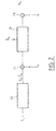
- Fig. 1 illustrates a known device for obtaining an antenna gain in transmission and reception.
- the device comprises an array of antennae (10 0 ),(10 1 ),...,(10 N-1 ), a transmission weighting module (11) and a reception weighting module (15).
- ⁇ i is the angle between a reference axis and the normal to the antenna of index i
- R the radius of curvature of the array
- ⁇ is the angular difference between two consecutive antennae in the array.
- the complex gain (or the complex gain function) in transmission can be written: with the same conventions as those adopted above and where e d ⁇ is the vector x corresponding to a plane wave transmitted in the direction ⁇ .
- the weighting vectors in reception and transmission mode will be called respectively b u and b d .
- the array of antennae of a base station receives signals transmitted by a plurality of mobile terminals.
- the signals transmitted by the different mobile terminals are separated by means of the use of orthogonal codes on transmission and filters adapted to these codes on reception. In practice, however, the separation of the different signals received is not perfect.
- the criterion to be maximised is then the ratio of signal to noise plus interference, the latter being due to the signals transmitted by the other mobile terminals.
- the downlink between a base station and a given mobile terminal is disturbed not only by the background noise but by the interference due to the signals transmitted by the said base station to other mobile terminals.
- optimise the weighting vector in reception mode, b u by estimating the uplink channel and the density of interference at the base station, it is quite different with regard to the optimisation of the weighting vector in transmission mode, b d .
- EP0999658 discloses a method for beamforming in a mobile telecommunications system, where in order to maximize the SNR, the downlink weighting vector employed by the base station is determined using information supplied by the wireless terminal.
- the aim of the invention is to propose a method for determining the transmission weighting vector, b d , optimising the ratio of signal to noise plus interference on the downlink and requiring the transmission only of a small quantity of information on the uplink.
- the invention is defined by a method for obtaining a transmission gain function by means of an array of antennae and a weighting of the signals received or to be transmitted by vectors ( b ) of N complex coefficients, referred to as weighting vectors, N being the number of antennae in the array, the array transmitting to a telecommunication terminal on a transmission channel, referred to as the downlink channel, a downlink transmission signal (S d ) and the said terminal transmitting to the said array on a transmission channel, referred to as the uplink channel, an uplink transmission signal (S u ), the said uplink channel being disturbed by a first isotropic noise (N) and/or a first directional noise, referred to as the uplink interference (I u ), the said downlink channel being disturbed by a second isotropic noise (N') and/or a second directional noise, referred to as the downlink interference (I d ).
- D u first noise matrix
- D d second noise matrix
- the first weighting vector ( b u ) is obtained for a first working frequency ( ⁇ u ) of the array and the second weighting vector ( b d ) is obtained for a second working frequency ( ⁇ d ) of the array.
- H u is the transformation matrix at the frequency ( f u )
- H + d is the pseudo-inverse matrix of the matrix H d
- D u is the first noise matrix
- D d is the second noise matrix
- the array transmits on a plurality of downlink channels a plurality of transmission signals to a plurality of telecommunication terminals and receives from them a plurality of transmission signals transmitted on a plurality of uplink channels and if each downlink channel j relating to a terminal j of the said plurality is associated with a second weighting vector b d ( j ), the second noise matrix relating to the downlink channel j is a diagonal matrix of size MxM and of components ⁇ 2 dk ( j )+ ⁇ d ( j ).
- N ' 0 / I d ( j ) where ⁇ 2 / dk ( j ) is the power of the downlink interference for the downlink channel in the direction k, ⁇ d ( j ) is a coefficient characterising the power transfer on the downlink channel j, N' 0 is the power of the second isotropic noise, and I d is the total power of the downlink interference.
- the said coefficient ⁇ d (j) is estimated from a coefficient characterising the orthogonality of the uplink channel j .
- the coefficient ⁇ d ( j ) can be transmitted to the array by the terminal j on the associated uplink channel.
- the invention is also defined by a device adapted to implement the method which has just been disclosed.
- a first general idea at the basis of the invention is to sample the transmission and reception gain functions in order to construct transmission and reception gain vectors.
- optimum weighting vectors in terms of ratio of signal to noise plus interference, can then be obtained from transmission and reception gain vectors according to matrix equations.
- a second general idea at the basis of the invention is to obtain a transmission weighting vector, optimum in terms of ratio of signal to noise plus interference obtained, from the reception gain weighting vector assumed itself to be optimum.
- weighting vectors can be obtained from a series of samples of the corresponding gain function.
- G( ⁇ ) be the antenna gain function obtained by means of a weighting vector b .
- the image of C N by h f s is a vector sub-space of C M with a dimension at most equal to N , which will be denoted Im f . If a base of C N is chosen, for example the canonical base, and a base of C M , it is possible to express the linear application h f s by a matrix H f of size MxN which is at most of rank N.
- G be any gain vector corresponding to a sampled gain function.
- H + / f (H * T / f .H f ) -1 .H *T / f is the pseudo-inverse matrix of the matrix H f with H *T / f a conjugate transpose of the matrix H f .
- the vectors e k are the weighting vectors of the array making it possible to form beams in the directions ⁇ k .
- H' f H f .T -1
- This equation makes it possible in particular to obtain, at a second working frequency, a sampled gain diagram which is as close as possible to the one, referred to as the reference, obtained at a first working frequency.
- Equation (10) applies advantageously to the array of antennae of a base station in a mobile telecommunication system operating in FDD (Frequency Division Duplex) mode.
- a frequency f d is used on the downlinks and a frequency f u distinct from f d is used on the uplinks.
- Equation (11) makes it possible, as has been seen, to obtain, at the transmission frequency f u , a sampled gain diagram which is as close as possible to a reference diagram obtained at the reception frequency f d .
- the interference profile that is to say the angular distribution of the power of the interference, is not necessarily the same on the downlink channel as on the uplink channel. This is because the directions of the interfering sources are not necessarily identical in transmission and reception. Consequently, though the reception gain diagram is optimum for a reception interference profile, it will not necessarily be so for a transmission interference profile. As will be shown later, if the transmission and reception interference profiles differ, equation (11) must be modified in order to take account of this difference.
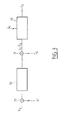
- Fig. 2 depicts the assembly consisting of the uplink channel (20), the array of antennae (22) and the reception weighting module (23).
- the effect of the noise has been represented by the addition (21) of a directional noise I u due to the interfering signals, and at (24) an isotropic centred white Gaussian background noise N.
- Fig. 3 depicts the assembly consisting of the downlink channel (30), the array of antennae (32) and the transmission weighting module (33).
- the effect of the noise has been represented by the addition at (31) of a directional noise I d due to the interfering signals and at (34) by a centred isotropic white Gaussian background noise N'.
- This vector has P ' from amongst M non-zero coefficients, where P' is the number of propagation paths of the channel.
- the matrix D u can be estimated at the base station from a measurement of the noise power and the interference in the directions ⁇ k .
- the matrix D d cannot be estimated as simply.
- the matrix D u can be estimated at the base station from a measurement of the noise power and the interference in the directions ⁇ k , for example during a period of silence of the mobile terminal.
- the matrix D d cannot be estimated as simply.
- the value of ⁇ can then be estimated directly by the base station, for example at the power control loop.
- the interference power attributable to the mobile terminals TS j in the direction ⁇ k can be written: where the indices between parentheses have been added so as to distinguish the quantities relating to the different downlink channels (that is to say intended for the different mobile terminals) and where:
- the coefficient of orthogonality of the downlink channel, ⁇ d (j 0 ) is little different from that of the uplink channel, ⁇ u (j 0 ) , the above three quantities arc available at the base station without a return of information by the mobile terminal being necessary.
- the power transfer coefficient, ⁇ d (j 0 ) is transmitted to the base station on the uplink channel from TS j0 or directly estimated by the latter. It is therefore possible to obtain the matrix D d for a slight additional cost in terms of conveyance resources.
- Fig. 4 illustrates an example of a device according to one embodiment of the invention. For reasons of simplicity, the processing of a single communication with a mobile terminal has been depicted.
- the device installed at the base station, comprises an array of antennae (40 0 ),(40 1 ),..(40 N-1 ) coupled by means of duplexers to a first reception weighting module (45), weighting the signals received by the different antennae by means of a first weighting vector, b u , and to a second transmission weighting module (41), weighting a signal to be transmitted by a second weighting vector, b d .
- the N outputs of antennae are directed to a module (46) estimating, in a manner known per se, the optimum weighting vector b u .
- Estimators of the noise power matrices (43) and (44) estimate respectively the matrices D u 2 and D d 2 .
- the matrices D u 2 and D d 2 are supplied to a matrix calculation module (42) which calculates the vector b d from the vector b u according to equation (22).
- the vector b d is then transmitted to the weighting module (41).
- the matrix D d 2 is evaluated in (44) by means of equation (23).
- the estimation module (44) receives an estimation of the coupling coefficient, ⁇ d or ⁇ according to circumstances, as well as interference powers ⁇ 2 / dk in the directions ⁇ k and the total power I d .
- the values ⁇ 2 / dk are advantageously calculated from equation (24) using the values of the transmission signals, S d (j), j ⁇ j0 , intended for the mobile terminals other than the one in question ( j 0 ) and the gain vectors, G d ( j ), j ⁇ j 0 , which are associated with them.
Abstract
Description
- The present invention concerns in general terms a method for obtaining a gain function in transmission mode. More particularly, the present invention relates to a method for obtaining an antenna gain in transmission mode for a base station in a mobile telecommunication system. It makes it possible to obtain an antenna gain in transmission mode from an antenna gain in reception mode.
- The formation of beams or the elimination of interfering signals is well known in the field of narrow-band antenna processing. Each uses an array of antennae, generally linear and uniform (that is to say with a constant pitch) and a signal weighting module. More precisely, if it is wished to form a beam in reception mode, the signals received by the different antennae are weighted by a set of complex coefficients before being added. Conversely, if it is wished to form a channel in transmission mode, the signal to be transmitted is weighted by a set of complex coefficients and the signals thus obtained are transmitted by the different antennae.
- Fig. 1 illustrates a known device for obtaining an antenna gain in transmission and reception. The device comprises an array of antennae (100),(101),...,(10N-1), a transmission weighting module (11) and a reception weighting module (15). The signals received by the different antennae, (xi ), i=0...N-1 are weighted at (130),(131),..,(13N-1) by a set of complex coefficients (bui ), i=0,...,N-1 before being added at (14) in order to give a signal Ru . Conversely, a signal to be transmitted Sd is weighted as (120),(121)...,(12N-1) by a set of complex coefficients (bdi ), i=0,..,N-1, before being transmitted by the different antennae.
- If the vector of the received signals and the vector of the weighting coefficients are respectively denoted
x =(x0 , x 1,...,xN -1) T and bu =(bu 0,bu 1,...,buN -1) T , it is possible to write:
- The complex gain (or the complex gain function of the antenna) in reception mode can be written:where

eu represents the vectorx corresponding to a plane wave arriving at an angle of incidence , and
Alternatively: - Likewise, the complex gain (or the complex gain function) in transmission can be written:with the same conventions as those adopted above and where

ed is the vectorx corresponding to a plane wave transmitted in the direction .
The weighting vectors in reception and transmission mode will be called respectivelybu andbd . - When the array of antennae is functioning in reception mode at a given frequency, different known methods, notably the Wiener filtering method, make it possible to determine the weighting vector
bu which maximises the signal to noise ratio. In a mobile telecommunications system, the array of antennae of a base station receives signals transmitted by a plurality of mobile terminals. In the context of a transmission in CDMA (Code Division Multiple Access) mode, the signals transmitted by the different mobile terminals are separated by means of the use of orthogonal codes on transmission and filters adapted to these codes on reception. In practice, however, the separation of the different signals received is not perfect. For an uplink between a given mobile terminal and the base station which serves it, the criterion to be maximised is then the ratio of signal to noise plus interference, the latter being due to the signals transmitted by the other mobile terminals. Likewise, the downlink between a base station and a given mobile terminal is disturbed not only by the background noise but by the interference due to the signals transmitted by the said base station to other mobile terminals. Though it is relatively easy to optimise the weighting vector in reception mode,bu , by estimating the uplink channel and the density of interference at the base station, it is quite different with regard to the optimisation of the weighting vector in transmission mode,bd . This is because the estimation of the downlink channel and the density of interference cannot be made directly at the base station and a transmission of this information by the mobile terminals is necessary. However, this transmission of information consumes transport resources on the uplink, which can be disadvantageous, notably in the case of rapid variations in the channel transfer function, for example when the mobile terminal is moving at high speed. - EP0999658 discloses a method for beamforming in a mobile telecommunications system, where in order to maximize the SNR, the downlink weighting vector employed by the base station is determined using information supplied by the wireless terminal.
- The aim of the invention is to propose a method for determining the transmission weighting vector,
bd , optimising the ratio of signal to noise plus interference on the downlink and requiring the transmission only of a small quantity of information on the uplink. - To this end, the invention is defined by a method for obtaining a transmission gain function by means of an array of antennae and a weighting of the signals received or to be transmitted by vectors (
b ) of N complex coefficients, referred to as weighting vectors, N being the number of antennae in the array, the array transmitting to a telecommunication terminal on a transmission channel, referred to as the downlink channel, a downlink transmission signal (Sd) and the said terminal transmitting to the said array on a transmission channel, referred to as the uplink channel, an uplink transmission signal (Su), the said uplink channel being disturbed by a first isotropic noise (N) and/or a first directional noise, referred to as the uplink interference (Iu), the said downlink channel being disturbed by a second isotropic noise (N') and/or a second directional noise, referred to as the downlink interference (Id). A first weighting vector (b u ) having been determined in order to maximise, on reception by the array, the ratio ((C/I+N) u ) of the received signal coming from the said terminal to the noise plus interference disturbing the said uplink channel, a second weighting vector (b d ) maximising, on reception by the terminal, the ratio ((C/I+N) d ) of the received signal coming from the network to the noise plus interference disturbing the downlink channel, is calculated from the said first weighting vector in the form of a matrix product comprising a first noise matrix (Du) which is a function of the power of the first isotropic noise and/or the power of the first directional noise and a second noise matrix (Dd) which is a function of the power of the second isotropic noise and/or the power of the second directional noise. - According to one embodiment, the first weighting vector (
b u ) is obtained for a first working frequency (ƒu ) of the array and the second weighting vector (b d ) is obtained for a second working frequency (ƒd ) of the array. - Advantageously, a gain function being represented by a vector, referred to as the gain vector (
G ), of M complex samples of the said gain function taken in M distinct directions (k), the said gain vector being expressed as the product of a weighting vector (b ) and a transformation matrix dependent on the working frequency of the array, the second weighting vectorb d is obtained from the first weighting vectorb u by: - The first noise matrix can be expressed as a diagonal matrix of size MxM and of components
G u =H u .b u . - In a similar manner, the second noise matrix can be expressed as a diagonal matrix of size MxM and of components
C d is a vector consisting of the samples of the function of the transfer function of the downlink channel taken in the said M directions and Id is the total power of the downlink interference. - If the array transmits on a plurality of downlink channels a plurality of transmission signals to a plurality of telecommunication terminals and receives from them a plurality of transmission signals transmitted on a plurality of uplink channels and if each downlink channel j relating to a terminal j of the said plurality is associated with a second weighting vector
b d (j), the second noise matrix relating to the downlink channel j is a diagonal matrix of size MxM and of components - The downlink interference power in the direction k, σ 2 / dk(j), can be estimated according to the power of the transmitted signals Sd(j') on the downlink channels j' distinct from j by:where βd(j) is an orthogonality coefficient of the downlink channel j and gdk(j') is the kth coefficient of the gain vector

G d (j')=Hdb d (j') relating to the downlink channel j'. - Advantageously, the said coefficient βd(j) is estimated from a coefficient characterising the orthogonality of the uplink channel j.
- The coefficient γ d (j) can be transmitted to the array by the terminal j on the associated uplink channel.
- The invention is also defined by a device adapted to implement the method which has just been disclosed.
- The characteristics of the invention mentioned above, as well as others, will emerge more clearly from a reading of the following description given in relation to the accompanying figures, amongst which:
- Fig. 1 depicts schematically a known device for obtaining an antenna gain function;
- Fig. 2 depicts schematically an uplink transmission channel in a mobile telecommunication system;
- Fig. 3 depicts schematically a downlink transmission channel in a mobile telecommunication system;
- Fig. 4 depicts schematically a device for obtaining an antenna gain function according to one embodiment of the invention.
-
- A first general idea at the basis of the invention is to sample the transmission and reception gain functions in order to construct transmission and reception gain vectors. As will be shown, optimum weighting vectors, in terms of ratio of signal to noise plus interference, can then be obtained from transmission and reception gain vectors according to matrix equations.
- A second general idea at the basis of the invention is to obtain a transmission weighting vector, optimum in terms of ratio of signal to noise plus interference obtained, from the reception gain weighting vector assumed itself to be optimum.
- It will shown first of all that the weighting vectors can be obtained from a series of samples of the corresponding gain function.
- Consider first of all a linear uniform array, formed by N antennae spaced apart by a pitch d and operating at the frequency f. The antennae gain function G0(), obtained in the absence of any weighting (that is to say with
b 0 =(1,1,...,1) T ): - This function has zeros for the values ϕk=2kπ/N, k a non-zero integer such that ϕ k ∈[-π,π[, that is to say in the directions for which sin k =k.c/Nfd, when this expression has a direction. The phase difference between two consecutive zeros in the gain diagram is constant and is equal to Δϕ=2πlN. The angular difference between two consecutive zeros of the diagram varies in terms of Arcsin., a function whose derivative is increasing on [-1,1] and is therefore minimum for the angular difference between the first and second zeros. It is therefore bounded by Δmin=c/Nfd if N is sufficiently great. It will be assumed that the frequencies used are less than f0 where f0 is the natural frequency of the array. It can be concluded from this that the spectrum of the function G0() has a support bounded by 1/Δmin=N/2.
- In more general terms, let G() be the antenna gain function obtained by means of a weighting vector
b . G can be expressed as the Fourier transform (FT) (in reception) or the inverse Fourier transform (in transmission) of the complex weighting distribution of the antenna, namely:with xi =i.d; this gives: Gu ()=B(sin) with and likewise Gd ()=B'(sin) with
 The function b(x) being bounded by N.d, the difference between two zeros of the function B or B' is at least λ/N.d and therefore all the more so 2/N. Given the increase in the derivative of the function Arcsin. the minimum difference between two zeros of the function G is 2/N. The function G therefore has a spectrum bounded by N/2.
- According to the Shannon sampling theorem, it is concluded from this that it is possible to reconstitute the function G() if sampling is carried out at a frequency greater than the Nyquist frequency, that is to say N. In other words, for an angular range [-π/2,π/2], a minimum of M>π.N samples are necessary, where M is an integer. In practice K.N samples can be taken with K integer, K≥4.
- For a circular array, it can be shown that 1/Δmin=N and the angular range being [-π,π], M (M>π.N and M integer) angularly equidistributed samples also suffice to rebuild the function G().
- In the general case of the sampling of any gain function G(), it is necessary first to filter G() by means of an anti-aliasing filter before sampling it. It then suffices to take M samples of the diagram filtered over the entire angular range in order to reconstitute the filtered diagram.
- The samples of a gain function, possibly filtered by anti-aliasing filtering, if necessary, will be denoted gk , k=0,..,M-1 that is to say gk =G'(k) where the instances of k are M angles equidistributed over [-π/2,π/2] or [-π,π] and where it is assumed that G' was the filtered version of the reference complex diagram.
- It is now possible to define a linear application, hf s of C N in C M which makes the vector h f / s(
b )=G =(g 0,g 1,..,gM -1) T where gk =G(b ,k) correspond to any weighting vectorb . The image of C N by hf s is a vector sub-space of C M with a dimension at most equal to N, which will be denoted Im f . If a base of C N is chosen, for example the canonical base, and a base of C M, it is possible to express the linear application hf s by a matrix Hf of size MxN which is at most of rank N. - Let
G be any gain vector corresponding to a sampled gain function. Let us seek the vectorb such that h f / s(b ) is as close as possible toG in the sense of a certain metric. There will be taken as a norm the Euclidian norm on C M, namelyIf it exists, the sought-for vector
b is then such that h f / s(b )=G p whereG p is the orthogonal projection of the vector G onto Im f . If the matrix Hf is of rank N, the sought-for vectorb exists and can be written: - In order to express the matrix Hf , it is necessary to agree on a base of the starting space and a base of the arrival space. It is possible to choose as the base of C M the canonical base and as a base of C N a base adapted to the description of the plane waves of frequency f. Consider the distinct vectors
e k , k=0,..,N-1, such thate k =(ek ,0,ek ,1,..,ek , N -1) T with ek , 1 =exp(j . 2πƒd / c . i.sin k )=exp(jπ.η.i.sin k ) with η=f/f0 and where the instances of k belong to the interval [-π/2,π/2]. The vectorse k are the weighting vectors of the array making it possible to form beams in the directions k . The vectorse k form a base if the determinant of the coordinates of the instances ofe k in the canonical base of C N is non-zero. This determinant is a Vandermonde determinant which is equal towith ϕ k =πηsin k . This determinant is equal to zero if and only if there are two angles p and q such that sin p -sin q =2/η. In other words, for η<1 the N vectors
e k always form a base and for η=1 only the case p = -q = π/2 is excluded. The directions can, for example, be chosen so as to be equally distributed, that is to say such that k=kπ/N with k=-(N-1)/2,...,0,..,(N-1)/2. In this case, the matrix Hf has as its components:or: with Ψpq=πη(sin(pπ/N)-sin(qπ/M))
- Alternatively, it is possible to choose as a starting base another base adapted to the frequency f, the one formed by the vectors
e 'k , such that e'k,i=exp(jπ.η.i.sin k ) with sink=2klηN and k=-(N-1)/2,...,0,..,(N-1)/2. These vectors exist if |sin k |≤1,∀k, that is to say for η>1-1/N, and in this case the vectorse 'k form a base which has the advantage of being orthogonal. - Alternatively, it is possible to choose as the starting base the canonical base of CN , which has the advantage of not depending on the frequency. In this case, the matrix H'f expressed in this base is written:
e k in the canonical base, that is to say Tpp'=exp(jπpsin(p'/N)). It was seen above that this matrix had a non-zero Vandermonde determinant and was consequently not reversible. - Assume now that it is sought to approximate a gain function obtained at a first frequency f1 , f1≤f0 and denote the vector of the samples associated with this gain function
G 1 =h f1 / s(b 1 ). Let a second working frequency be f2 , f2≤f0. G belonging to C M, if the matrix Hf2 is of rank N, it is possible to find a vectorb 2 such that h f2(b2 ) is the projection of h f1 / s(b 1 ) onto Imf2 . The vectorb 2 is obtained by means of the matrix equation: - This equation makes it possible in particular to obtain, at a second working frequency, a sampled gain diagram which is as close as possible to the one, referred to as the reference, obtained at a first working frequency.
- Equation (10) applies advantageously to the array of antennae of a base station in a mobile telecommunication system operating in FDD (Frequency Division Duplex) mode. In such a system, a frequency fd is used on the downlinks and a frequency fu distinct from fd is used on the uplinks. Equation (10) then makes it possible to directly obtain the weighting vector on transmission
bd from the weighting vector on receptionbu - Equation (11) makes it possible, as has been seen, to obtain, at the transmission frequency fu , a sampled gain diagram which is as close as possible to a reference diagram obtained at the reception frequency fd . However, the interference profile, that is to say the angular distribution of the power of the interference, is not necessarily the same on the downlink channel as on the uplink channel. This is because the directions of the interfering sources are not necessarily identical in transmission and reception. Consequently, though the reception gain diagram is optimum for a reception interference profile, it will not necessarily be so for a transmission interference profile. As will be shown later, if the transmission and reception interference profiles differ, equation (11) must be modified in order to take account of this difference.
- Fig. 2 depicts the assembly consisting of the uplink channel (20), the array of antennae (22) and the reception weighting module (23). The effect of the noise has been represented by the addition (21) of a directional noise
I u due to the interfering signals, and at (24) an isotropic centred white Gaussian background noise N. - Just as the gain function can be represented by a gain vector, the channel can be modelled by a dimension vector M, defined as the angular sampling of the transfer function of the channel in the directions k , k=0,...,M-1 and denoted
C u =(cu 0,cu 1,..,cuM -1) T . This vector has P amongst M non-zero coefficients, where P is the number of channel propagation paths. For these P coefficients cuk , cuk=αuk .exp-j(2πfu .Luk /c+ϕuk ) where Luk is the length of the path concerned, αuk the coefficient of attenuation of the signal propagating along the said path and ϕuk the polarisation of the incident signal. - The signal Ru received by the base station can be written:
G u is the reception gain vector and Su is the signal transmitted by the mobile terminal. - The ratio of signal to noise plus interference is:where Pu is the power of the signal Su , N0 is the power of the background noise and

I 0 / uis the standardised vector whose components are assimilated to standardised centred Gaussian random variables N(0,σ uk 2) that is to say such thatand where Iu =E(
- Expression (13) can then be written:where

Ω u =D -1 / u.C u , Λ u =D uG u and
Expression (14) is maximal forΛ u =Ω u * and therefore for:b u , optimum in the sense of the maximisation of the ratio of signal to noise plus interference on the channel, can then be expressed: - Fig. 3 depicts the assembly consisting of the downlink channel (30), the array of antennae (32) and the transmission weighting module (33). The effect of the noise has been represented by the addition at (31) of a directional noise
I d due to the interfering signals and at (34) by a centred isotropic white Gaussian background noise N'. - Just like the uplink channel, the downlink channel can be modelled by a vector of dimension M, defined as the angular sampling of the transfer function of this channel in the directions k , k=0,..,M-1 and denoted
C d =(cd 0,cd 1,..,cdM -1) T . This vector has P' from amongst M non-zero coefficients, where P' is the number of propagation paths of the channel. For these P' coefficients cdk , cdk '=α dk '.exp-j(2πfd.Ldk' /c+ϕ dk ') where Ldk ' is the length of the path concerned, αdk' the coefficient of attenuation of the signal propagating on the said path and ϕdk' the polarisation of the incident signal. - The signal Rd received by the mobile terminal can be written:
G d is the transmission gain vector and Sd is the signal transmitted by the base station. - The ratio of signal to noise plus interference is:where Pd is the power of the signal Sd , and N'0 is the power of the background noise, and where

I 0 / dis the standardised vector whose components are assimilated to standardised centred random Gaussian variables N(0,σ dk 2 ), that is to say such thatand where
- Expression (18) can also be written:where

Ω d= D -1 / d..G d ,Λ d =D dC d and
Expression (19) is maximum forΩ d =Λ d * and therefore forbd , optimum in the sense of the maximisation of the ratio of signal to noise plus interference on the downlink channel, can then be expressed as: - If it is assumed that the transfer function of the downlink channel is identical to that of the uplink channel, that is to say if
Cd =C u , it is possible to derive from (16) and (21) the relationship between the optimum weighting vectorsbd andbu : - It should be noted that equation (11) is a particular case of equation (22) when D d=D -1 / u. This will be the case in particular if the noise on the uplink channel and the noise on the downlink channel consist solely of isotropic noise.
- The matrix Du can be estimated at the base station from a measurement of the noise power and the interference in the directions k . On the other hand the matrix D d cannot be estimated as simply.
- The matrix Du can be estimated at the base station from a measurement of the noise power and the interference in the directions k , for example during a period of silence of the mobile terminal. On the other hand the matrix D d cannot be estimated as simply.
- Let it be stated that
- Advantageously, it will be assumed that the power transfer coefficient does not depend on the frequency and is identical for the downlink channel and the uplink channel, namely
Cd =C u . The value of Γ can then be estimated directly by the base station, for example at the power control loop. - It is also possible to estimate the power of the interference in the direction k , that is to say Id.σ 2 / dk, by expressing the fact that it is due to the transmission in the direction k of signals intended for mobile terminals TSj other than the one considered, that is to say TSj0. Because of the overlap of the transmission gain diagrams for the signals intended for the mobile terminals TSj on the one hand and the mobile terminal TSj0 on the other hand and the lack of orthogonality between these signals, the interference power attributable to the mobile terminals TSj in the direction k can be written:where the indices between parentheses have been added so as to distinguish the quantities relating to the different downlink channels (that is to say intended for the different mobile terminals) and where:

- βd(j0) is the coefficient of orthogonality of the downlink channel, destined for TSj0;
- Sd(j) is the power of the transmission signal destined for the terminal TSj;
- gdk(j) is the kth coefficient of the gain vector
G d (j) relating to the transmission to TSj. -
- If it is assumed that the coefficient of orthogonality of the downlink channel, βd(j0), is little different from that of the uplink channel, βu(j0), the above three quantities arc available at the base station without a return of information by the mobile terminal being necessary. As seen above, the power transfer coefficient, γd(j0), is transmitted to the base station on the uplink channel from TSj0 or directly estimated by the latter. It is therefore possible to obtain the matrix D d for a slight additional cost in terms of conveyance resources.
- The only quantity in equation (24) liable to vary rapidly over time is the power of the transmission signals Sd(j). In the case of a transmission in DS-CDMA mode, it will for example be possible to update these power values at each transmission slot.
- It should be stated that equation (22) was obtained under the initial assumption of equality of the transfer functions of the downlink channel and uplink channel, that is to say:
Cd =C u . - If this identity is not satisfied, the vector
bd given by equation (22) is no longer optimum, that is to say no longer supplies the best ratio of signal to noise plus interference. - The ratio obtained is expressed from equations (18), (20) in the form:where it is indeed found that the ratio is maximum for

C d=C u . - Assuming now that the transfer functions of the uplink and downlink channels are random functions, this then gives:If the isotropic noises are disregarded, the numerator of (26) can be written:
 If it is assumed that:
that is to say if: - the distribution of the phases and the distribution of the amplitudes of cdk are independent and the same applies to cuk' ;
- the paths of the uplink and downlink channels relating to different directions have statistically decorrelated lengths Ldk and Ldk' ;
- Fig. 4 illustrates an example of a device according to one embodiment of the invention. For reasons of simplicity, the processing of a single communication with a mobile terminal has been depicted. The device, installed at the base station, comprises an array of antennae (400),(401),..(40N-1) coupled by means of duplexers to a first reception weighting module (45), weighting the signals received by the different antennae by means of a first weighting vector,
bu , and to a second transmission weighting module (41), weighting a signal to be transmitted by a second weighting vector,bd . When the device manages several communications with a plurality of mobile terminals, other weighting modules identical to the modules (41), (45) must be provided in parallel with these. The N outputs of antennae are directed to a module (46) estimating, in a manner known per se, the optimum weighting vectorbu . Estimators of the noise power matrices (43) and (44) estimate respectively the matrices Du 2 and Dd 2 . The matrices Du 2 and Dd 2 are supplied to a matrix calculation module (42) which calculates the vectorbd from the vectorbu according to equation (22). The vectorbd is then transmitted to the weighting module (41). The matrix Dd 2 is evaluated in (44) by means of equation (23). To do this, the estimation module (44) receives an estimation of the coupling coefficient, γ d or Γ according to circumstances, as well as interference powers σ 2 / dkin the directions k and the total power Id . The values σ 2 / dkare advantageously calculated from equation (24) using the values of the transmission signals, Sd(j), j≠j0, intended for the mobile terminals other than the one in question (j0 ) and the gain vectors, Gd (j),j≠j0 , which are associated with them. - Although the device described above has been depicted schematically in the form of functional modules, it goes without saying, however, that the various functions executed can be executed by means of a processor programmed for this purpose or by a plurality of dedicated processors.


The equation can then be written:

Claims (10)
- Method for obtaining a transmission gain function by means of an array of antennae, the signals received or to be transmitted being weighted by vectors (
b ) of N complex coefficients, referred to as weighting vectors, N being the number of antennae in the array, the array transmitting, to a telecommunication terminal on a transmission channel, referred to as the downlink channel, a downlink transmission signal (Sd) and the said terminal transmitting to the said array on a transmission channel, referred to as the uplink channel, an uplink transmission signal (Su), the said uplink channel being disturbed by a first isotropic noise (N) and/or a first directional noise, referred to as the uplink interference (Iu), the said downlink channel being disturbed by a second isotropic noise (N') and/or a second directional noise, referred to as the downlink interference (Id), characterised in that a first weighting vector (b u ) having been determined in order to maximise, on reception by the array, the ratio ((C/I+N) u ) of the received signal coming from the said terminal to the noise plus interference disturbing the said uplink channel, a second weighting vector (b d ) maximising, on reception by the terminal, the ratio ((C/I+N) d ) of the received signal coming from the network to the noise plus interference disturbing the downlink channel, is calculated from the said first weighting vector in the form of a matrix product comprising a first noise matrix (Du) which is a function of the power of the first isotropic noise and/or the power of the first directional noise and a second noise matrix (Dd) which is a function of the power of the second isotropic noise and/or the power of the second directional noise. - Method for obtaining a transmission gain function according to Claim 1, characterised in that the first weighting vector (
b u ) is obtained for a first working frequency (ƒu ) of the array and the second weighting vector (b d ) is obtained for a second working frequency (ƒd ) of the array. - Method for obtaining a transmission gain function according to Claim 2, characterised in that, a gain function being represented by a vector, referred to as a gain vector (
G ), of M complex samples of the said gain function taken in M distinct directions (k), the said gain vector being expressed as the product of a weighting vector (b ) and a transformation matrix dependent on the working frequency of the array, the second weighting vectorb d is obtained from the first weighting vectorb u by: - Method for obtaining a transmission gain function according to Claim 3, characterised in that the first noise matrix is a diagonal matrix of size MxM and of components
G u =H u .b u . - Method for obtaining a transmission gain function according to Claim 3 or 4, characterised in that the second noise matrix is a diagonal matrix of size MxM and of components
C d is a vector consisting of the samples of the function of the transfer function of the downlink channel taken in the said M directions and Id is the total power of the downlink interference. - Method for obtaining a transmission gain function according to Claim 3 or 4, characterised in that, the array transmitting on a plurality of downlink channels a plurality of transmission signals to a plurality of telecommunication terminals and receiving from them a plurality of transmission signals transmitted on a plurality of uplink channels, each downlink channel j relating to a terminal j in the said plurality being associated with a second weighting vector
b d (j), the second noise matrix relating to the downlink channel j is a diagonal matrix of size MxM and of components - Method for obtaining a transmission gain function according to Claim 6, characterised in that the downlink interference power in the direction k, σ 2 / dk (j), is estimated according to the power of the signals Sd (j') transmitted on the downlink channels j' distinct from j by:where βd(j) is an orthogonality coefficient of the downlink channel j and gdk(j') is the kth coefficient of the gain vector

G d (j')=Hdb d (j') relating to the downlink channel j'. - Method for obtaining a transmission gain function according to Claim 7, characterised in that the said coefficient βd(j) is estimated from a coefficient characterising the orthogonality of the uplink channel j.
- Method for obtaining a transmission gain function according to one of Claims 6 to 8, characterised in that the coefficient γ d (j) is transmitted to the array by the terminal j over the associated uplink channel.
- Transmission/reception device for a base station in a mobile telecommunication system, comprising an array (400,401,..,40N-1) of N antennae, means (45) for weighting the signals received by the said array with a first weighting vector (
b u ), means (41) for weighting the signals to be transmitted by the said array with of a second weighting vector (b d ), means (46) for determining a first weighting vector maximising a ratio of signal to noise and/or interference on reception, and means (42, 43, 44) for obtaining a transmission gain function adapted to implement the method according to one of the preceding claims, the said means for obtaining the gain function supplying the second weighting vector (b d ) to the said means (41) for weighting the signals.
Applications Claiming Priority (2)
| Application Number | Priority Date | Filing Date | Title |
|---|---|---|---|
| FR0014361 | 2000-10-31 | ||
| FR0014361A FR2816140B1 (en) | 2000-10-31 | 2000-10-31 | METHOD FOR OBTAINING TRANSMIT GAIN FUNCTION |
Publications (2)
| Publication Number | Publication Date |
|---|---|
| EP1204220A1 EP1204220A1 (en) | 2002-05-08 |
| EP1204220B1 true EP1204220B1 (en) | 2003-08-13 |
Family
ID=8856220
Family Applications (1)
| Application Number | Title | Priority Date | Filing Date |
|---|---|---|---|
| EP01402661A Expired - Lifetime EP1204220B1 (en) | 2000-10-31 | 2001-10-15 | Method for obtaining a transmission gain function |
Country Status (6)
| Country | Link |
|---|---|
| US (1) | US6552683B2 (en) |
| EP (1) | EP1204220B1 (en) |
| JP (1) | JP4070073B2 (en) |
| AT (1) | ATE247344T1 (en) |
| DE (1) | DE60100590D1 (en) |
| FR (1) | FR2816140B1 (en) |
Families Citing this family (5)
| Publication number | Priority date | Publication date | Assignee | Title |
|---|---|---|---|---|
| FR2816141B1 (en) * | 2000-10-31 | 2002-12-06 | Mitsubishi Electric Inf Tech | METHOD FOR OBTAINING TRANSMIT GAIN FUNCTION |
| US7643429B2 (en) * | 2006-11-06 | 2010-01-05 | Fujitsu Limited | Interference measuring and mapping method and apparatus for wireless networks using relay stations |
| US7877097B2 (en) * | 2006-11-06 | 2011-01-25 | Fujitsu Limited | Reuse pattern network scheduling using interference levels |
| US20080171551A1 (en) * | 2007-01-11 | 2008-07-17 | Fujitsu Limited | Reuse pattern network scheduling using load levels |
| US9793967B2 (en) * | 2013-11-21 | 2017-10-17 | The Hong Kong University Of Science And Technology | Weighted sum data rate maximization using linear transceivers in a full-duplex multi-user MIMO system |
Family Cites Families (5)
| Publication number | Priority date | Publication date | Assignee | Title |
|---|---|---|---|---|
| US5434578A (en) * | 1993-10-22 | 1995-07-18 | Westinghouse Electric Corp. | Apparatus and method for automatic antenna beam positioning |
| US6400780B1 (en) * | 1998-11-06 | 2002-06-04 | Lucent Technologies Inc. | Space-time diversity for wireless systems |
| FI108588B (en) * | 1998-12-15 | 2002-02-15 | Nokia Corp | Method and radio system for transmitting a digital signal |
| JP3341701B2 (en) * | 1999-03-05 | 2002-11-05 | 日本電気株式会社 | Array antenna transmitter |
| US6441784B1 (en) * | 2000-06-30 | 2002-08-27 | Arraycomm, Inc. | Method and apparatus for uplink and downlink weight prediction in adaptive array systems |
-
2000
- 2000-10-31 FR FR0014361A patent/FR2816140B1/en not_active Expired - Fee Related
-
2001
- 2001-10-09 JP JP2001311218A patent/JP4070073B2/en not_active Expired - Fee Related
- 2001-10-15 AT AT01402661T patent/ATE247344T1/en not_active IP Right Cessation
- 2001-10-15 DE DE60100590T patent/DE60100590D1/en not_active Expired - Lifetime
- 2001-10-15 EP EP01402661A patent/EP1204220B1/en not_active Expired - Lifetime
- 2001-10-22 US US09/982,800 patent/US6552683B2/en not_active Expired - Fee Related
Also Published As
| Publication number | Publication date |
|---|---|
| ATE247344T1 (en) | 2003-08-15 |
| FR2816140A1 (en) | 2002-05-03 |
| JP2002359585A (en) | 2002-12-13 |
| DE60100590D1 (en) | 2003-09-18 |
| US20020075967A1 (en) | 2002-06-20 |
| JP4070073B2 (en) | 2008-04-02 |
| EP1204220A1 (en) | 2002-05-08 |
| FR2816140B1 (en) | 2002-12-06 |
| US6552683B2 (en) | 2003-04-22 |
Similar Documents
| Publication | Publication Date | Title |
|---|---|---|
| CN111313951B (en) | IRS (inter-Range instrumentation Standard) auxiliary secure communication wireless transmission method based on non-ideal CSI (channel State information) | |
| US7020490B2 (en) | Radio communication system | |
| EP2979410B1 (en) | Channel estimation in wireless communications with beamforming | |
| US8040278B2 (en) | Adaptive antenna beamforming | |
| EP1724943A1 (en) | Multiple input-multiple output communication system | |
| KR101268691B1 (en) | Apparatus and method for receiving data by beamforming in a smart antenna system | |
| CN101569055B (en) | Antenna system and method for operating an antenna system | |
| Wang et al. | Joint beamforming for intelligent reflecting surface-assisted millimeter wave communications | |
| EP1206049B1 (en) | Method for obtaining a transmission gain function | |
| CN114095318A (en) | Intelligent super-surface-assisted hybrid configuration millimeter wave communication system channel estimation method | |
| Khan et al. | Antenna beam-forming for a 60 Ghz transceiver system | |
| Li et al. | Joint adaptive aoa and polarization estimation using hybrid dual-polarized antenna arrays | |
| EP1204220B1 (en) | Method for obtaining a transmission gain function | |
| CN108987948B (en) | Antenna structure composed of multi-port sub-array and base frequency signal processor | |
| EP1198150B1 (en) | Method of estimating a downlink channel | |
| JP4806659B2 (en) | Array antenna apparatus, array antenna communication method, relay communication system, and relay communication method | |
| Mahfoudi et al. | Joint range extension and localization for low‐power wide‐area network | |
| CN116056118A (en) | Wireless communication transmission method and system based on active and passive hybrid intelligent super surface | |
| CN114172546B (en) | Multi-parameter iterative estimation method in RIS auxiliary MIMO system | |
| US8014981B2 (en) | Angular-domain channel model and channel estimation | |
| Avdeyenko et al. | Efficiency of spatial signal processing in wireless communications | |
| US7876850B2 (en) | Wireless communication system with diversity/MIMO array branch decoupling | |
| Fedosov et al. | Investigation of the Influence of Spatial Correlation on the Performance of the MIMO System When Using the Adaptation Algorithm | |
| EP1204162A1 (en) | Method for obtaining an antenna gain function | |
| JP5827167B2 (en) | Array antenna |
Legal Events
| Date | Code | Title | Description |
|---|---|---|---|
| PUAI | Public reference made under article 153(3) epc to a published international application that has entered the european phase |
Free format text: ORIGINAL CODE: 0009012 |
|
| AK | Designated contracting states |
Kind code of ref document: A1 Designated state(s): AT BE CH CY DE DK ES FI FR GB GR IE IT LI LU MC NL PT SE TR |
|
| AX | Request for extension of the european patent |
Free format text: AL;LT;LV;MK;RO;SI |
|
| 17P | Request for examination filed |
Effective date: 20020912 |
|
| AKX | Designation fees paid |
Designated state(s): AT BE CH CY DE DK ES FI FR GB GR IE IT LI LU MC NL PT SE TR |
|
| GRAH | Despatch of communication of intention to grant a patent |
Free format text: ORIGINAL CODE: EPIDOS IGRA |
|
| RAP1 | Party data changed (applicant data changed or rights of an application transferred) |
Owner name: MITSUBISHI ELECTRIC INFORMATION TECHNOLOGY CENTRE |
|
| GRAH | Despatch of communication of intention to grant a patent |
Free format text: ORIGINAL CODE: EPIDOS IGRA |
|
| GRAA | (expected) grant |
Free format text: ORIGINAL CODE: 0009210 |
|
| AK | Designated contracting states |
Designated state(s): AT BE CH CY DE DK ES FI FR GB GR IE IT LI LU MC NL PT SE TR |
|
| PG25 | Lapsed in a contracting state [announced via postgrant information from national office to epo] |
Ref country code: AT Free format text: LAPSE BECAUSE OF FAILURE TO SUBMIT A TRANSLATION OF THE DESCRIPTION OR TO PAY THE FEE WITHIN THE PRESCRIBED TIME-LIMIT Effective date: 20030813 Ref country code: CH Free format text: LAPSE BECAUSE OF FAILURE TO SUBMIT A TRANSLATION OF THE DESCRIPTION OR TO PAY THE FEE WITHIN THE PRESCRIBED TIME-LIMIT Effective date: 20030813 Ref country code: IT Free format text: LAPSE BECAUSE OF FAILURE TO SUBMIT A TRANSLATION OF THE DESCRIPTION OR TO PAY THE FEE WITHIN THE PRESCRIBED TIME-LIMIT;WARNING: LAPSES OF ITALIAN PATENTS WITH EFFECTIVE DATE BEFORE 2007 MAY HAVE OCCURRED AT ANY TIME BEFORE 2007. THE CORRECT EFFECTIVE DATE MAY BE DIFFERENT FROM THE ONE RECORDED. Effective date: 20030813 Ref country code: BE Free format text: LAPSE BECAUSE OF FAILURE TO SUBMIT A TRANSLATION OF THE DESCRIPTION OR TO PAY THE FEE WITHIN THE PRESCRIBED TIME-LIMIT Effective date: 20030813 Ref country code: TR Free format text: LAPSE BECAUSE OF FAILURE TO SUBMIT A TRANSLATION OF THE DESCRIPTION OR TO PAY THE FEE WITHIN THE PRESCRIBED TIME-LIMIT Effective date: 20030813 Ref country code: FI Free format text: LAPSE BECAUSE OF FAILURE TO SUBMIT A TRANSLATION OF THE DESCRIPTION OR TO PAY THE FEE WITHIN THE PRESCRIBED TIME-LIMIT Effective date: 20030813 Ref country code: LI Free format text: LAPSE BECAUSE OF FAILURE TO SUBMIT A TRANSLATION OF THE DESCRIPTION OR TO PAY THE FEE WITHIN THE PRESCRIBED TIME-LIMIT Effective date: 20030813 Ref country code: NL Free format text: LAPSE BECAUSE OF FAILURE TO SUBMIT A TRANSLATION OF THE DESCRIPTION OR TO PAY THE FEE WITHIN THE PRESCRIBED TIME-LIMIT Effective date: 20030813 |
|
| REG | Reference to a national code |
Ref country code: GB Ref legal event code: FG4D |
|
| REG | Reference to a national code |
Ref country code: CH Ref legal event code: EP |
|
| REG | Reference to a national code |
Ref country code: IE Ref legal event code: FG4D |
|
| REF | Corresponds to: |
Ref document number: 60100590 Country of ref document: DE Date of ref document: 20030918 Kind code of ref document: P |
|
| PG25 | Lapsed in a contracting state [announced via postgrant information from national office to epo] |
Ref country code: IE Free format text: LAPSE BECAUSE OF NON-PAYMENT OF DUE FEES Effective date: 20031015 Ref country code: CY Free format text: LAPSE BECAUSE OF FAILURE TO SUBMIT A TRANSLATION OF THE DESCRIPTION OR TO PAY THE FEE WITHIN THE PRESCRIBED TIME-LIMIT Effective date: 20031015 Ref country code: LU Free format text: LAPSE BECAUSE OF NON-PAYMENT OF DUE FEES Effective date: 20031015 |
|
| PG25 | Lapsed in a contracting state [announced via postgrant information from national office to epo] |
Ref country code: MC Free format text: LAPSE BECAUSE OF NON-PAYMENT OF DUE FEES Effective date: 20031031 |
|
| PG25 | Lapsed in a contracting state [announced via postgrant information from national office to epo] |
Ref country code: DK Free format text: LAPSE BECAUSE OF FAILURE TO SUBMIT A TRANSLATION OF THE DESCRIPTION OR TO PAY THE FEE WITHIN THE PRESCRIBED TIME-LIMIT Effective date: 20031113 Ref country code: GR Free format text: LAPSE BECAUSE OF FAILURE TO SUBMIT A TRANSLATION OF THE DESCRIPTION OR TO PAY THE FEE WITHIN THE PRESCRIBED TIME-LIMIT Effective date: 20031113 Ref country code: SE Free format text: LAPSE BECAUSE OF FAILURE TO SUBMIT A TRANSLATION OF THE DESCRIPTION OR TO PAY THE FEE WITHIN THE PRESCRIBED TIME-LIMIT Effective date: 20031113 |
|
| PG25 | Lapsed in a contracting state [announced via postgrant information from national office to epo] |
Ref country code: DE Free format text: LAPSE BECAUSE OF FAILURE TO SUBMIT A TRANSLATION OF THE DESCRIPTION OR TO PAY THE FEE WITHIN THE PRESCRIBED TIME-LIMIT Effective date: 20031114 |
|
| PG25 | Lapsed in a contracting state [announced via postgrant information from national office to epo] |
Ref country code: ES Free format text: LAPSE BECAUSE OF FAILURE TO SUBMIT A TRANSLATION OF THE DESCRIPTION OR TO PAY THE FEE WITHIN THE PRESCRIBED TIME-LIMIT Effective date: 20031124 |
|
| PG25 | Lapsed in a contracting state [announced via postgrant information from national office to epo] |
Ref country code: PT Free format text: LAPSE BECAUSE OF FAILURE TO SUBMIT A TRANSLATION OF THE DESCRIPTION OR TO PAY THE FEE WITHIN THE PRESCRIBED TIME-LIMIT Effective date: 20040113 |
|
| NLV1 | Nl: lapsed or annulled due to failure to fulfill the requirements of art. 29p and 29m of the patents act | ||
| ET | Fr: translation filed | ||
| REG | Reference to a national code |
Ref country code: CH Ref legal event code: PL |
|
| PLBE | No opposition filed within time limit |
Free format text: ORIGINAL CODE: 0009261 |
|
| STAA | Information on the status of an ep patent application or granted ep patent |
Free format text: STATUS: NO OPPOSITION FILED WITHIN TIME LIMIT |
|
| REG | Reference to a national code |
Ref country code: IE Ref legal event code: MM4A |
|
| 26N | No opposition filed |
Effective date: 20040514 |
|
| PG25 | Lapsed in a contracting state [announced via postgrant information from national office to epo] |
Ref country code: GB Free format text: LAPSE BECAUSE OF NON-PAYMENT OF DUE FEES Effective date: 20051015 |
|
| GBPC | Gb: european patent ceased through non-payment of renewal fee |
Effective date: 20051015 |
|
| PGFP | Annual fee paid to national office [announced via postgrant information from national office to epo] |
Ref country code: FR Payment date: 20081022 Year of fee payment: 8 |
|
| REG | Reference to a national code |
Ref country code: FR Ref legal event code: ST Effective date: 20100630 |
|
| PG25 | Lapsed in a contracting state [announced via postgrant information from national office to epo] |
Ref country code: FR Free format text: LAPSE BECAUSE OF NON-PAYMENT OF DUE FEES Effective date: 20091102 |