EP1203176B1 - Dichtung für geringe belastung - Google Patents
Dichtung für geringe belastung Download PDFInfo
- Publication number
- EP1203176B1 EP1203176B1 EP00953951A EP00953951A EP1203176B1 EP 1203176 B1 EP1203176 B1 EP 1203176B1 EP 00953951 A EP00953951 A EP 00953951A EP 00953951 A EP00953951 A EP 00953951A EP 1203176 B1 EP1203176 B1 EP 1203176B1
- Authority
- EP
- European Patent Office
- Prior art keywords
- gasket
- air impermeable
- substantially air
- expanded ptfe
- multilayer
- Prior art date
- Legal status (The legal status is an assumption and is not a legal conclusion. Google has not performed a legal analysis and makes no representation as to the accuracy of the status listed.)
- Expired - Lifetime
Links
- 229920001343 polytetrafluoroethylene Polymers 0.000 claims description 258
- 239000004810 polytetrafluoroethylene Substances 0.000 claims description 257
- 229920001971 elastomer Polymers 0.000 claims description 23
- 239000000806 elastomer Substances 0.000 claims description 23
- 239000000945 filler Substances 0.000 claims description 20
- 229910000831 Steel Inorganic materials 0.000 claims description 12
- 239000010959 steel Substances 0.000 claims description 12
- 239000010702 perfluoropolyether Substances 0.000 claims description 6
- 229920002379 silicone rubber Polymers 0.000 claims description 6
- 239000011521 glass Substances 0.000 claims description 4
- 229920006169 Perfluoroelastomer Polymers 0.000 claims description 3
- 239000011152 fibreglass Substances 0.000 claims description 3
- 229920001973 fluoroelastomer Polymers 0.000 claims description 3
- 230000037361 pathway Effects 0.000 claims 2
- 239000010410 layer Substances 0.000 description 226
- 238000012360 testing method Methods 0.000 description 88
- 239000000463 material Substances 0.000 description 68
- 230000000052 comparative effect Effects 0.000 description 30
- 239000012530 fluid Substances 0.000 description 26
- 238000013023 gasketing Methods 0.000 description 22
- 229920000544 Gore-Tex Polymers 0.000 description 17
- 230000008901 benefit Effects 0.000 description 13
- 238000010276 construction Methods 0.000 description 12
- 238000010438 heat treatment Methods 0.000 description 10
- 239000000126 substance Substances 0.000 description 10
- 239000002184 metal Substances 0.000 description 8
- 238000000034 method Methods 0.000 description 8
- 238000007789 sealing Methods 0.000 description 8
- 238000002791 soaking Methods 0.000 description 8
- 230000035699 permeability Effects 0.000 description 7
- 229920000295 expanded polytetrafluoroethylene Polymers 0.000 description 6
- 230000006872 improvement Effects 0.000 description 6
- 239000012528 membrane Substances 0.000 description 6
- XLYOFNOQVPJJNP-UHFFFAOYSA-N water Substances O XLYOFNOQVPJJNP-UHFFFAOYSA-N 0.000 description 6
- 239000007788 liquid Substances 0.000 description 5
- 229910001220 stainless steel Inorganic materials 0.000 description 5
- 239000010935 stainless steel Substances 0.000 description 5
- 239000002344 surface layer Substances 0.000 description 5
- 229920002943 EPDM rubber Polymers 0.000 description 4
- 238000001816 cooling Methods 0.000 description 4
- 230000005484 gravity Effects 0.000 description 4
- 238000009434 installation Methods 0.000 description 4
- 239000002131 composite material Substances 0.000 description 3
- 239000011148 porous material Substances 0.000 description 3
- 239000002356 single layer Substances 0.000 description 3
- 238000010998 test method Methods 0.000 description 3
- LFQSCWFLJHTTHZ-UHFFFAOYSA-N Ethanol Chemical compound CCO LFQSCWFLJHTTHZ-UHFFFAOYSA-N 0.000 description 2
- 239000002033 PVDF binder Substances 0.000 description 2
- 230000015556 catabolic process Effects 0.000 description 2
- 230000008859 change Effects 0.000 description 2
- 239000011248 coating agent Substances 0.000 description 2
- 238000000576 coating method Methods 0.000 description 2
- 230000006835 compression Effects 0.000 description 2
- 238000007906 compression Methods 0.000 description 2
- 229920001577 copolymer Polymers 0.000 description 2
- 238000006731 degradation reaction Methods 0.000 description 2
- 238000007598 dipping method Methods 0.000 description 2
- 230000013011 mating Effects 0.000 description 2
- 238000013508 migration Methods 0.000 description 2
- 230000005012 migration Effects 0.000 description 2
- 239000012466 permeate Substances 0.000 description 2
- 229920002981 polyvinylidene fluoride Polymers 0.000 description 2
- 239000000843 powder Substances 0.000 description 2
- 230000001105 regulatory effect Effects 0.000 description 2
- 239000011347 resin Substances 0.000 description 2
- 229920005989 resin Polymers 0.000 description 2
- 239000002904 solvent Substances 0.000 description 2
- BFKJFAAPBSQJPD-UHFFFAOYSA-N tetrafluoroethene Chemical group FC(F)=C(F)F BFKJFAAPBSQJPD-UHFFFAOYSA-N 0.000 description 2
- 230000037303 wrinkles Effects 0.000 description 2
- 241001330988 Palmyra Species 0.000 description 1
- 108091092920 SmY RNA Proteins 0.000 description 1
- 241001237710 Smyrna Species 0.000 description 1
- 239000000853 adhesive Substances 0.000 description 1
- 230000001070 adhesive effect Effects 0.000 description 1
- 239000010425 asbestos Substances 0.000 description 1
- 230000000712 assembly Effects 0.000 description 1
- 238000000429 assembly Methods 0.000 description 1
- 230000004888 barrier function Effects 0.000 description 1
- 230000009286 beneficial effect Effects 0.000 description 1
- 239000011230 binding agent Substances 0.000 description 1
- 230000005540 biological transmission Effects 0.000 description 1
- 238000009530 blood pressure measurement Methods 0.000 description 1
- 230000009172 bursting Effects 0.000 description 1
- 230000003247 decreasing effect Effects 0.000 description 1
- 230000001627 detrimental effect Effects 0.000 description 1
- 230000003292 diminished effect Effects 0.000 description 1
- 230000000694 effects Effects 0.000 description 1
- 235000019441 ethanol Nutrition 0.000 description 1
- 229920002313 fluoropolymer Polymers 0.000 description 1
- 238000010348 incorporation Methods 0.000 description 1
- 239000011261 inert gas Substances 0.000 description 1
- 238000007641 inkjet printing Methods 0.000 description 1
- 238000004519 manufacturing process Methods 0.000 description 1
- 239000003921 oil Substances 0.000 description 1
- 230000003204 osmotic effect Effects 0.000 description 1
- 238000012856 packing Methods 0.000 description 1
- 125000005010 perfluoroalkyl group Chemical group 0.000 description 1
- 230000000737 periodic effect Effects 0.000 description 1
- 239000004033 plastic Substances 0.000 description 1
- 229920003023 plastic Polymers 0.000 description 1
- 239000000047 product Substances 0.000 description 1
- 229910052895 riebeckite Inorganic materials 0.000 description 1
- 238000010186 staining Methods 0.000 description 1
- 229920003051 synthetic elastomer Polymers 0.000 description 1
- 239000005061 synthetic rubber Substances 0.000 description 1
- 238000012546 transfer Methods 0.000 description 1
- 238000011144 upstream manufacturing Methods 0.000 description 1
Images


Classifications
-
- F—MECHANICAL ENGINEERING; LIGHTING; HEATING; WEAPONS; BLASTING
- F16—ENGINEERING ELEMENTS AND UNITS; GENERAL MEASURES FOR PRODUCING AND MAINTAINING EFFECTIVE FUNCTIONING OF MACHINES OR INSTALLATIONS; THERMAL INSULATION IN GENERAL
- F16J—PISTONS; CYLINDERS; SEALINGS
- F16J15/00—Sealings
- F16J15/02—Sealings between relatively-stationary surfaces
- F16J15/06—Sealings between relatively-stationary surfaces with solid packing compressed between sealing surfaces
- F16J15/10—Sealings between relatively-stationary surfaces with solid packing compressed between sealing surfaces with non-metallic packing
- F16J15/102—Sealings between relatively-stationary surfaces with solid packing compressed between sealing surfaces with non-metallic packing characterised by material
-
- F—MECHANICAL ENGINEERING; LIGHTING; HEATING; WEAPONS; BLASTING
- F16—ENGINEERING ELEMENTS AND UNITS; GENERAL MEASURES FOR PRODUCING AND MAINTAINING EFFECTIVE FUNCTIONING OF MACHINES OR INSTALLATIONS; THERMAL INSULATION IN GENERAL
- F16J—PISTONS; CYLINDERS; SEALINGS
- F16J15/00—Sealings
- F16J15/02—Sealings between relatively-stationary surfaces
- F16J15/06—Sealings between relatively-stationary surfaces with solid packing compressed between sealing surfaces
- F16J15/10—Sealings between relatively-stationary surfaces with solid packing compressed between sealing surfaces with non-metallic packing
- F16J15/104—Sealings between relatively-stationary surfaces with solid packing compressed between sealing surfaces with non-metallic packing characterised by structure
-
- Y—GENERAL TAGGING OF NEW TECHNOLOGICAL DEVELOPMENTS; GENERAL TAGGING OF CROSS-SECTIONAL TECHNOLOGIES SPANNING OVER SEVERAL SECTIONS OF THE IPC; TECHNICAL SUBJECTS COVERED BY FORMER USPC CROSS-REFERENCE ART COLLECTIONS [XRACs] AND DIGESTS
- Y10—TECHNICAL SUBJECTS COVERED BY FORMER USPC
- Y10T—TECHNICAL SUBJECTS COVERED BY FORMER US CLASSIFICATION
- Y10T428/00—Stock material or miscellaneous articles
- Y10T428/21—Circular sheet or circular blank
- Y10T428/215—Seal, gasket, or packing
-
- Y—GENERAL TAGGING OF NEW TECHNOLOGICAL DEVELOPMENTS; GENERAL TAGGING OF CROSS-SECTIONAL TECHNOLOGIES SPANNING OVER SEVERAL SECTIONS OF THE IPC; TECHNICAL SUBJECTS COVERED BY FORMER USPC CROSS-REFERENCE ART COLLECTIONS [XRACs] AND DIGESTS
- Y10—TECHNICAL SUBJECTS COVERED BY FORMER USPC
- Y10T—TECHNICAL SUBJECTS COVERED BY FORMER US CLASSIFICATION
- Y10T428/00—Stock material or miscellaneous articles
- Y10T428/21—Circular sheet or circular blank
- Y10T428/218—Aperture containing
-
- Y—GENERAL TAGGING OF NEW TECHNOLOGICAL DEVELOPMENTS; GENERAL TAGGING OF CROSS-SECTIONAL TECHNOLOGIES SPANNING OVER SEVERAL SECTIONS OF THE IPC; TECHNICAL SUBJECTS COVERED BY FORMER USPC CROSS-REFERENCE ART COLLECTIONS [XRACs] AND DIGESTS
- Y10—TECHNICAL SUBJECTS COVERED BY FORMER USPC
- Y10T—TECHNICAL SUBJECTS COVERED BY FORMER US CLASSIFICATION
- Y10T428/00—Stock material or miscellaneous articles
- Y10T428/21—Circular sheet or circular blank
- Y10T428/219—Edge structure
-
- Y—GENERAL TAGGING OF NEW TECHNOLOGICAL DEVELOPMENTS; GENERAL TAGGING OF CROSS-SECTIONAL TECHNOLOGIES SPANNING OVER SEVERAL SECTIONS OF THE IPC; TECHNICAL SUBJECTS COVERED BY FORMER USPC CROSS-REFERENCE ART COLLECTIONS [XRACs] AND DIGESTS
- Y10—TECHNICAL SUBJECTS COVERED BY FORMER USPC
- Y10T—TECHNICAL SUBJECTS COVERED BY FORMER US CLASSIFICATION
- Y10T428/00—Stock material or miscellaneous articles
- Y10T428/23—Sheet including cover or casing
- Y10T428/233—Foamed or expanded material encased
-
- Y—GENERAL TAGGING OF NEW TECHNOLOGICAL DEVELOPMENTS; GENERAL TAGGING OF CROSS-SECTIONAL TECHNOLOGIES SPANNING OVER SEVERAL SECTIONS OF THE IPC; TECHNICAL SUBJECTS COVERED BY FORMER USPC CROSS-REFERENCE ART COLLECTIONS [XRACs] AND DIGESTS
- Y10—TECHNICAL SUBJECTS COVERED BY FORMER USPC
- Y10T—TECHNICAL SUBJECTS COVERED BY FORMER US CLASSIFICATION
- Y10T428/00—Stock material or miscellaneous articles
- Y10T428/23—Sheet including cover or casing
- Y10T428/239—Complete cover or casing
-
- Y—GENERAL TAGGING OF NEW TECHNOLOGICAL DEVELOPMENTS; GENERAL TAGGING OF CROSS-SECTIONAL TECHNOLOGIES SPANNING OVER SEVERAL SECTIONS OF THE IPC; TECHNICAL SUBJECTS COVERED BY FORMER USPC CROSS-REFERENCE ART COLLECTIONS [XRACs] AND DIGESTS
- Y10—TECHNICAL SUBJECTS COVERED BY FORMER USPC
- Y10T—TECHNICAL SUBJECTS COVERED BY FORMER US CLASSIFICATION
- Y10T428/00—Stock material or miscellaneous articles
- Y10T428/249921—Web or sheet containing structurally defined element or component
- Y10T428/249953—Composite having voids in a component [e.g., porous, cellular, etc.]
- Y10T428/249981—Plural void-containing components
-
- Y—GENERAL TAGGING OF NEW TECHNOLOGICAL DEVELOPMENTS; GENERAL TAGGING OF CROSS-SECTIONAL TECHNOLOGIES SPANNING OVER SEVERAL SECTIONS OF THE IPC; TECHNICAL SUBJECTS COVERED BY FORMER USPC CROSS-REFERENCE ART COLLECTIONS [XRACs] AND DIGESTS
- Y10—TECHNICAL SUBJECTS COVERED BY FORMER USPC
- Y10T—TECHNICAL SUBJECTS COVERED BY FORMER US CLASSIFICATION
- Y10T428/00—Stock material or miscellaneous articles
- Y10T428/31504—Composite [nonstructural laminate]
- Y10T428/3154—Of fluorinated addition polymer from unsaturated monomers
- Y10T428/31544—Addition polymer is perhalogenated
Definitions
- the present invention relates to gaskets and, more particularly, to a gasket that forms a seal under less stress than required with existing gaskets.
- PTFE polytetrafluoroethylene
- US-A-5 160 773 As disclosed in U.S. Patent No. 3,953,566 to Gore, this material has numerous properties making it highly desirable as a gasket. These properties include being readily compressible and conformable, being chemically resistant, having relatively high strength, and being far less prone to creep and loss of sealing pressure than non-expanded full density PTFE alone.
- the gasket is used to seal the junction between flanges, such as between pipes.
- expanded PTFE is a desirable material for the gaskets because the expanded PTFE gasket can be placed between the flanges, and the flanges can then be pressed together with the application of force, such as by tightening of bolts. This application of force compresses the expanded PTFE. As the expanded PTFE is compressed, its initial pore volume is reduced, thus densifying the expanded PTFE. Particularly with metal-to-metal flanges, it is possible to apply sufficient force (or "stress") to the flanges to fully densify the expanded PTFE.
- the pore volume is reduced to substantially zero, such that a fluid contained within the pipes is prevented from leaking between the flanges by the densified, non-porous PTFE gasket, which seals the flanges.
- expanded PTFE is so conformable, it would be desirable to use expanded PTFE to seal these commonly uneven flanges.
- glass-lined steel piping flanges, glass flanges, or FRP piping flanges may deform, fracture, or break upon the application of a high amount of stress.
- an expanded PTFE gasket may not be completely densified to reach a non-porous state, and therefore does not become leak proof, because the maximum stress that can be applied to the flanges without breaking them is not sufficient to so densify the gasket.
- envelope gaskets are subject to a number of disadvantages.
- the envelope jacket often will fold over on itself during installation of the gasket, thereby creating creases in the gasket that cause leaks.
- there may be pin hole leaks in the envelope itself causing corrosive material to attack the envelope filler resulting in degradation of the filler.
- sealing stress can be diminished, causing a leak to occur.
- Another problem, which can result, is that the degraded filler material can contaminate the fluids that were contained within the pipe or vessel.
- the envelope jacket of PTFE will separate from the conformable filler material and ripples or folds may occur merely from stretching the envelope over the filler, again causing leaks to occur. Also, if uneven flange torquing occurs, the jacket may become overstressed and burst, once again allowing the corrosive material to attack the filler resulting in degradation of the filler and loss of the seal. Another problem is that these envelope gaskets are also subject to cold flow or creep, which requires periodic bolt retorquing.
- an envelope gasket is employed with a PTFE envelope within which is an elaborate metal filling consisting of wound or nested turns of thin metal strips perforated to provide resilience in the direction of their width. Individual turns can move or collapse to different extents, thereby accommodating lack of flatness of the surfaces to be sealed. Turns of fluid-impervious material may be distributed among the turns of the perforated strips.
- the gasket has some advantages, it still suffers from many of the disadvantages mentioned above associated with envelope gaskets, such as chemical attack of the metal filling under certain conditions.
- a gasket comprising an envelope of chemically resistant PTFE and a metallic packing ring within the envelope is shaped to form cells.
- the cells may be filled with an inert gas under pressure so that increased loads on the gasket may be cushioned.
- This homogeneous PTFE /microballoon gasketing material exhibits enhanced compressibility and sealing characteristics due to the incorporation of microballoons, while maintaining the resistance to chemicals and the enhanced temperature characteristics provided by PTFE.
- the addition of the microballoons to the PTFE lowers the tensile strength properties that would be provided by pure PTFE gasketing. Plus, this gasket does not enjoy some of the aforementioned advantages that expanded PTFE has over non-expanded PTFE.
- microballoon filled layers are each formed to be within the range of from 20 - 25% of the overall thickness of the resultant gasket material, while the central PTFE section is within the range of from 50 - 60% of the overall gasket thickness.
- these ratios are important because if the outer surface layers are each formed to be below 20% of the overall gasket thickness, the finished composite sheet loses compressibility, while if they are formed to be above 25%, creep resistance and tensile strength are sacrificed in the finished product.
- this gasket is an improvement upon the homogeneously loaded microballoon gasket, and avoids the problems associated with envelope gaskets, it still does not adequately solve the problems of many applications. It is still left trying to trade off compressibility with creep resistance and tensile strength. This gasket also does not enjoy some of the aforementioned advantages of expanded PTFE compared to non-expanded PTFE.
- a unitary shielded gasket assembly for use in corrosive environments having a synthetic rubber gasket as a core and a shielding material of expanded high density PTFE with an adhesive on at least one surface of the shielding material at least partially enveloping the surface of the core gasket.
- This gasket does not suffer from the wrinkles and folds that can result from a two-piece envelope gasket; however, it still suffers from the inherent problem of chemical attack problems resulting from pinhole leaks in the outer sheath.
- an annular gasket composed of porous PTFE for sanitary piping in which the surface layer of a gasket inner part directly contacting with sealed fluid is formed as a pore-free fused solidified layer. It is stated that the osmotic leak from the gasket inner part is prevented by the pore-free fused solidified layer formed in the gasket inner part although the gasket is composed of a porous material. Moreover, it is stated that since the fused solidified layer is formed only on the surface layer of the gasket inner part, the intrinsic properties of porous PTFE such as flexibility and affinity are not spoiled.
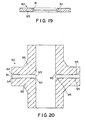
- FIG. 20 This figure shows a side cross-sectional view of a gasketed flange assembly 90 of two conventional glass-lined steel flanges 96 which have the rounded convex mating edges 95 which contact the gasket 91 on part of its top and bottom surfaces 94. It can be seen that if only the surface layer of the internal diameter 93 of the gasket 91 is impermeable to the contained fluid, there is a ready leak path 92 through that exposed part of the gasket 91 which is not impermeable to the fluid.
- the present invention provides a multilayer, unitary gasket including at least one inner layer of expanded PTFE disposed between a first substantially air impermeable outer layer and a second substantially air impermeable outer layer, and a substantially air impermeable region bridging the first and second substantially air impermeable layers.
- the present invention provides a multilayer, unitary gasket including an annular ring having a top surface, a bottom surface, an inside edge, an outside edge and an axis; a first substantially air impermeable layer disposed on the top surface; a second substantially air impermeable layer disposed on the bottom surface; at least one layer of expanded PTFE disposed between the first and second substantially air impermeable layers; and a substantially air impermeable region bridging the first and second substantially air impermeable layers; wherein all of the layers are oriented substantially perpendicular to the axis.
- the present invention provides an annular gasket having an inner perimeter, an outer perimeter, a top surface, and a bottom surface including a first chamber of expanded PTFE disposed adjacent to the inner perimeter having a first air impermeable top layer on the top surface and a first air impermeable bottom layer on the bottom surface; a second chamber of expanded PTFE disposed adjacent to the outer perimeter having a second air impermeable top layer on the top surface and a second air impermeable bottom layer on the bottom surface; and a substantially air impermeable region disposed between first and second chambers.
- the present invention provides an improved expanded PTFE gasket that provides a substantially air impermeable seal upon the application of a relatively low load to the components joined or sealed by the gasket, thereby applying a relatively low stress to the gasket.
- air impermeable as used herein is meant resistant to transport of air through a material. Permeability may be measured using any known technique.
- low stress as used herein is meant a stress below that required to fully densify a porous expanded PTFE gasket (less than about 20,700 kPa (3000psi)). It generally takes at least about 20,700 kPa (3000 psi) to fully densify a porous expanded PTFE gasket. Most low stress applications generally apply less than about 10340 kPa (1500 psi) gasket stress, while some low stress applications may apply less than about 2070 kPa (300 psi) gasket stress.
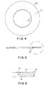
- Gasket 10 is shown in the shape of an annular ring, although any shape gasket may be used. Gasket 10 has a first chamber 11 and a second chamber 12. Between first chamber 11 and second chamber 12 is a substantially air impermeable region 13.
- substantially air impermeable region 13 has a reduced thickness when compared to that of first chamber 11 and second chamber 12.
- the substantially air impermeable region 13 serves to isolate first chamber 11 from second chamber 12, while at the same time being connected to both first chamber 11 and second chamber 12.
- first chamber 11 and second chamber 12 are both made up of an inner layer 15 of expanded PTFE sandwiched between substantially air impermeable layers 14 on the top and bottom surfaces of expanded PTFE layer 15.
- Substantially air impermeable layers 14 are preferably made of densified expanded PTFE. Densified expanded PTFE is preferred in that being PTFE it has the highest level of chemical resistance, while the expansion characteristics provide high levels of strength and creep resistance. Substantially air impermeable layers 14 may in fact comprise a plurality of such densified expanded PTFE layers.
- air impermeable materials may also be used, including tetrafluoroethylene/hexafluoropropylene copolymer (FEP), tetrafluoroethylene/(perfluoroalkyl) vinyl ether copolymer (PFA), and skived PTFE.
- FEP tetrafluoroethylene/hexafluoropropylene copolymer
- PFA tetrafluoroethylene/(perfluoroalkyl) vinyl ether copolymer
- skived PTFE tetrafluoroethylene/hexafluoropropylene copolymer
- air impermeable layers 14 may be made of expanded PTFE impregnated with a filler such as an elastomer, a fluoroelastomer, a perfluoroelastomer, or a perfluoropolyether silicone elastomer.
- Expanded PTFE layer 15 may also comprise a plurality of individual layers of expanded PTFE.
- Substantially air impermeable region 13 is preferably densified expanded PTFE although it may comprise any substantially air impermeable material, such a FEP, PFA and skived PTFE.
- substantially air impermeable region 13 may be made of expanded PTFE impregnated with a filler such as an elastomer, a fluoroelastomer, a perfluoroelastomer, or a perfluoropolyether silicone elastomer.
- a filler such as an elastomer, a fluoroelastomer, a perfluoroelastomer, or a perfluoropolyether silicone elastomer.
- the more chemically resistant the type of elastomer used or other type of nonpermeable coating or filler used the more applications the gasket will be able to provide an effective sealing solution.
- gasket 10 is subjected to the application of stress by mating flanges (not shown) on either side of the gasket substantially along the axis of the gasket (which is in the direction normal to the page as shown in Figure 1).
- expanded PTFE layer 15 compresses somewhat, thereby reducing the porosity of expanded PTFE layer 15.
- Substantially air impermeable layers 14 are preferably thin such that the surface of gasket 10 covered by substantially air impermeable layers 14 can conform to any irregularities in the surface of the flanges to which they mate.
- Substantially air impermeable layers 14 of thicknesses equal to or less than 1 mm can be useful, however, thicknesses equal to or less than 0.5 mm are generally even more useful, with thicknesses equal to or less than 0.15 mm generally preferred. In some applications where a very high level of conformability is desired, thicknesses equal to or less than 0.1 mm, 0.05mm and even 0.025 mm would be preferred.
- substantially air impermeable layers 14 serve to form an air impermeable barrier against the transfer of fluid from inside the pipes to the surface of the flanges where they may leak around gasket 10. Because the gasket of the present invention is intended for use in applications where there is low available stress, expanded PTFE layers 15 generally do not fully compress. There is generally therefore some porosity left in expanded PTFE layers 15. It is thus possible for fluid contained within the sealed pipes to permeate through expanded PTFE layers 15 in the direction of the arrow shown in Figure 3.
- Substantially air impermeable region 13 prevents the escape of this fluid to the environment, however.
- the fluid may permeate expanded PTFE layer 15 in first chamber 11 but is blocked from permeating into second chamber 12 by the substantially air impermeable region 13. In this manner, a leak-proof seal is provided.
- substantially air impermeable layers 14 and the substantially air impermeable region 13 will be substantially impermeable to fluids in general, including liquids, even low surface tension liquids, such as many solvents.
- a desired advantage of the present invention is that upon migration of fluid into the expanded PTFE layer 15 of first chamber 11, and upon subsequent blockage of further fluid permeation by substantially air impermeable region 13, the fluid that is "trapped" in first chamber 11 exerts an outward force against substantially air impermeable layers 14. This phenomenon helps further conform and seal substantially air impermeable layers 14 to the surfaces of the flanges, thereby improving the seal by gasket 10. Without being limited by theory, it is believed that second chamber 12 helps to provide a resistant force behind substantially air impermeable region 13 that helps prevent rupture of substantially air impermeable region 13.
- Gasket 10 is preferably made by wrapping one or more layers of densified ePTFE on a mandrel to form a first air impermeable layer 14; wrapping one or more (preferably considerably more) layers of expanded PTFE around the air impermeable layer 14 to form the expanded PTFE layer 15; wrapping one or more substantially air impermeable layers around the expanded PTFE layer 15 to form the second (outer) substantially air impermeable layer 14.
- the wrapped tube After heating the wrapped tube / mandrel assembly to fuse the different layers into a unitary body, the wrapped tube may then be cooled and then longitudinally cut and laid flat in the form of a sheet. The sheet may then be stamped into annular rings of desired size. Each ring is then subjected to a compressive treatment between, for example, two metal tubes in order to compress a discreet portion of the annular ring to form substantially air impermeable region 13.
- gasket 20 comprises a single chamber 21 with substantially air impermeable region 13 disposed on the inner periphery of gasket 20.
- Chamber 21 is formed of an inner layer 15 of expanded PTFE sandwiched by outer layers of substantially air impermeable layers 14, similar to the construction of the chambers 11 and 12 discussed in conjunction of the first embodiment.
- This embodiment is generally preferred in those type of applications where it is undesirable to have any ingress of fluid into the gasket, such as with many pharmaceutical applications.
- gasket 30 has a single chamber 31 with substantially air impermeable region 13 disposed on the outer periphery of gasket 30.
- chamber 31 is preferably made of a layer 15 of expanded PTFE sandwiched by substantially air impermeable layers 14.
- an additional distinct advantage of the present invention over conventional envelope gaskets is the tight contact produced between the inner layer 15 to both the substantially impermeable layers 14 and the substantially air impermeable region 13. It is especially important to have this tight contact between the inner layer 15 and the substantially impermeable region 13. This tight contact prevents the aforementioned problems associated with envelope gaskets pertaining to creating wrinkles, folds and creases in the jacket, which can cause leaks.
- the tight contact also provides backing to the substantially air impermeable region 13 which makes it less susceptible to damage during installation and while in use.
- a gasket which represents a typical envelope gasket, and in particular represents the jacketed gasket 80 disclosed in previously mentioned Japanese Laid-Open Patent Application Number 4-331876 to Ueda et al.
- This gasket 80 has free space 81 between the jacket or sheath 82 and the core 83. This free space (lacking tight contact) can be detrimental to the gasket in application due to the above stated reasons.
- An annular gasket of the present invention was produced in the following manner.
- a continuous expanded PTFE sheet produced from fine powder PTFE resin through paste-forming techniques was obtained and expanded in directions 90 degrees opposed to each other (longitudinally and transversely) to form a microporous expanded PTFE sheet as taught in US Patent No. 4,187,390 to Gore.
- This sheet, having a thickness of about 0.015 mm was then rolled between two rollers at a fixed gap to compress the microporous expanded PTFE sheet into a full density non-porous expanded PTFE sheet.
- This non-porous sheet had a final thickness of about 0.005 mm and a final width of about 1270 mm. Five layers of this full density sheet were wrapped around a 584 mm diameter mandrel.
- a second continuous expanded PTFE sheet produced from fine powder PTFE resin through paste-forming techniques was obtained and expanded in directions 90 degrees opposed to each other (longitudinally and transversely) to form a microporous expanded PTFE sheet as taught in US Patent No. 4,187,390 to Gore.
- One hundred layers of this second microporous expanded PTFE sheet, measuring approximately 1600 mm wide and 0.038 mm thick was then wrapped on the mandrel covering the previously wrapped full density expanded PTFE sheet.
- An annular ring shape having an inner diameter of 89 mm and outer diameter of 135 mm was then cut from the sheet and selectively compressed to form the substantially air impermeable region 13 between the full density PTFE substantially air impermeable layers 14.
- the substantially air impermeable region 13 was formed in the annular gasket of this example by compressing the gasket between annular dies having an inner diameter of 104.8 mm and outer diameter of 108.0 mm. The dies were heated to 200°C and loaded to a pressure around 51.7 MPa (7500 psi). The load was maintained for approximately fifteen seconds.
- Both substantially air impermeable layers 14 of this example measured to be 0.025 mm (0.001 inches) thick.
- This gasket was an annular ring gasket with an inner diameter of 89 mm and outer diameter of 135 mm and a total thickness of 3.0 mm.
- the compressed air impermeable region 13 had an inner diameter of 104.8 mm and an outer diameter of 108.0 mm. This is one version of the inventive gasket shown in Figures 1-3.
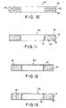
- FIG. 10 shows the cross section of this annular ring gasket 40 which comprises: outer layers 41 of conformable microporous expanded PTFE material; rigid inner layers 43 of full density expanded PTFE material attached to each of the outer layers 41 and a center layer 42 of conformable microporous expanded PTFE material attached between each of the rigid inner layers 43.
- the annular gasket had an inner diameter of 89 mm and an outer diameter of 135 mm and was 3.2 mm thick.
- FIG. 1 Another annular gasket in accordance with the present invention of the construction shown in Figures 1-3 was produced.
- a commercially available sheet of 0.125 inch (3.2 mm) thick GORE-TEX GR® Style R sheet gasketing described in Comparative Example 2 was obtained.
- the outer conformable microporous expanded PTFE layers 41 were peeled by hand from the sheet material exposing the rigid inner layers 43 of PTFE as the new outer layers.
- the rigid inner layers 43 of the GORE-TEX GR® Style R sheet gasketing were comprised of densified expanded PTFE material with a density at or near full density, 2.2 g/cc, and had a thickness of 0.15 mm (0.006 inches).
- An annular ring shape having an inner diameter of 89 mm and outer diameter of 135 mm was then cut from the peeled sheet and selectively compressed to form the substantially air impermeable region 13 between the full density PTFE substantially air impermeable layers 14.
- the substantially air impermeable region 13 was formed in the annular gasket of this example by compressing the gasket between annular dies having an inner diameter of 104.8 mm and outer diameter of 108.0 mm. The dies were heated to 200°C and loaded to a pressure around 51.7 MPa (7500 psi). The load was maintained for approximately fifteen seconds.
- the annular ring gasket had an inner diameter of 89 mm and outer diameter of 135 mm and thickness of 3.0 mm.
- the compressed air impermeable region 13 had an inner diameter of 104.8 mm and an outer diameter of 108.0 mm.
- a gasket in accordance with the present invention was produced in a manner similar to Example 1.
- the same full density non-porous expanded PTFE sheet produced in Example 1 was used to form the substantially air impermeable layers 14 and the same microporous expanded PTFE sheet produced in Example 1 was used to form the conformable microporous inner layer 15.
- An annular ring shape having an inner diameter of 89 mm and outer diameter of 135 mm was then cut from the sheet and selectively compressed to form the substantially air impermeable region 13 between the full density PTFE substantially air impermeable layers 14.
- the substantially air impermeable region 13 was formed by compressing the gasket between annular dies having an inner diameter of 104.8 mm and outer diameter of 108.0 mm. The dies were heated to 200°C and loaded to a pressure around 51.7 MPa (7500 psi). The load was maintained for approximately fifteen seconds.
- Both substantially air impermeable layers 14 of this example measured to be 0.01 mm (0.0004 inches) thick.
- This gasket was an annular ring gasket with an inner diameter of 89 mm and outer diameter of 135 mm and a total thickness of 3.0 mm.
- the compressed air impermeable region 13 had an inner diameter of 104.8 mm and an outer diameter of 108.0 mm.
- An annular gasket in accordance with the present invention of the construction shown in Figures 4-6 was produced in a manner similar to Example 3.
- a peeled sheet having outer layers of full density expanded PTFE with an inner layer of conformable microporous expanded PTFE was produced as in Example 3.
- An annular ring gasket was then cut from the peeled sheet having an inner diameter of 104.8 mm and an outer diameter of 160 mm.
- An air impermeable region 13 was then formed by compressing the ring gasket between annular dies having an inner diameter (104.8 mm) equal to the inner diameter of the gasket, and an outer diameter of 108.0 mm.
- the dies were heated to 200°C and loaded to a pressure around 51.7 MPa (7500 psi). The load was maintained for approximately fifteen seconds.
- the final annular gasket had an inner diameter of 104.8 mm and outer diameter of 160 mm and thickness of 3.0 mm.
- the compressed air impermeable region had an inner diameter 104.8 mm and an outer diameter of 108.0 mm.
- the air impermeable layers 14 had a thickness of 0.15 mm (0.006 inches).
- FIG. 11 demonstrates a further embodiment of the present invention where a conformable microporous expanded PTFE material cut in the form of an annular ring gasket is coated with a substantially air impermeable coating.
- a microporous expanded PTFE sheet of 0.125 inch (3.2 mm) thick GORE-TEX GR® sheet gasketing commercially available from W.L. Gore & Associates, Inc.
- An annular ring with an inner diameter of 86 mm and outer diameter of 133 mm was cut from the sheet.
- the annular ring was then coated with a perfluoropolyether silicone elastomer, SIFELTM 610, available from Shin-Etsu Chemical Co., Ltd., in the following way.
- the annular ring was dipped into a bath of the elastomer for a period of five minutes, allowing the elastomer to soak into the surface porosity of the GORE-TEX GR® sheet gasketing. Immediately after the five minutes of dipping, the excess elastomer was scraped form the surfaces of the annular ring. The coated annular ring was then cured in an oven at 175 °C for four hours producing the final annular ring gasket 50.
- both the air impermeable layers 14 and the air impermeable regions 13 were formed from the elastomer soaking into the porosity of the microporous expanded PTFE.
- the expanded PTFE inner layer 15 was that part of the expanded PTFE that the elastomer did not soak into.
- the air impermeable regions 13 were at both the inner and outer diameters of the gasket 50.
- the air impermeable layers 14 and air impermeable regions 13 were about 0.13 mm thick.
- An annular gasket in accordance with the present invention was produced in a manner similar to Example 1.
- the same full density non-porous expanded PTFE sheet produced in Example 1 was used to form the substantially air impermeable layers 14 and the same microporous expanded PTFE sheet produced in Example 1 was used to form the conformable microporous inner layer 15.
- An annular ring shape having an inner diameter of 89 mm and outer diameter of 135 mm was then cut from the sheet and selectively compressed to form the substantially air impermeable region 13 between the full density PTFE substantially air impermeable layers 14.
- the substantially air impermeable region 13 was formed by compressing the gasket between annular dies having an inner diameter of 104.8 mm and outer diameter of 108.0 mm. The dies were heated to 200°C and loaded to a pressure around 51.7 MPa (7500 psi). The load was maintained for approximately fifteen seconds.
- Both substantially air impermeable layers 14 of this example measured to be 0.05 mm (0.002 inches) thick.
- This gasket was an annular ring gasket with an inner diameter of 89 mm and outer diameter of 135 mm and a total thickness of 3.0 mm.
- the compressed air impermeable region 13 had an inner diameter of 104.8 mm and an outer diameter of 108.0 mm.
- An annular gasket in accordance with the present invention of the construction shown in Figures 7-9 was produced in a manner similar to Example 3.
- a peeled sheet having outer layers of full density expanded PTFE with an inner layer of conformable microporous expanded PTFE was produced as in Example 3.
- An annular ring shape was then cut from the peeled sheet having an inner diameter of 60 mm and an outer diameter of 108 mm.
- An air impermeable region 13 was then formed by compressing the ring gasket between annular dies having an outer diameter (108.0 mm) equal to the outer diameter of the gasket and an inner diameter of 104.8 mm.
- the dies were heated to 200°C and loaded to a pressure around 51.7 MPa (7500 psi). The load was maintained for approximately fifteen seconds.
- the final annular gasket had an inner diameter of 60 mm and outer diameter of 108 mm and thickness of 3.0 mm.
- the compressed air impermeable region had an inner diameter 104.8 mm and an outer diameter of 108.0 mm.
- the air impermeable layers 14 had a thickness of 0.15 mm (0.006 inches).
- a microporous expanded PTFE sheet of 0.125 inch (3.2 mm) thick GORE-TEX GR® sheet gasketing commercially available from W.L. Gore & Associates, Inc., was obtained.
- An annular ring gasket was cut from the sheet.
- the annular ring gasket had an inner diameter of 60.8 mm, an outer diameter of 107 mm and was 3.2 mm thick.
- An annular gasket in accordance with the present invention of the construction shown in Figures 4-6 was produced in a manner similar to Example 3.
- a peeled sheet having outer layers of full density expanded PTFE with an inner layer of conformable microporous expanded PTFE was produced as in Example 3.
- An annular ring shape was then cut from the peeled sheet having an inner diameter of 60.8 mm and an outer diameter of 107 mm.
- An air impermeable region 13 was then formed between the full density expanded PTFE substantially air impermeable layers 14 by compressing the ring gasket between annular dies having an inner diameter (60.8 mm) equal to the inner diameter of the gasket and an outer diameter of 64.0 mm.
- the dies were heated to 200°C and loaded to a pressure around 51.7 MPa (7500 psi). The load was maintained for approximately fifteen seconds.
- the annular ring gasket had an inner diameter of 60.8 mm and outer diameter of 107 mm and thickness of 3.0 mm.
- the compressed air impermeable region 13 had an inner diameter of 60.8 mm and an outer diameter of 64.0 mm.
- the air impermeable layers 14 had a thickness of 0.15 mm (0.006 inches).
- An annular gasket in accordance with the present invention of the construction shown in Figures 1-3 was produced in a manner similar to Example 3.
- a peeled sheet having outer layers of full density expanded PTFE with an inner layer of conformable microporous expanded PTFE was produced as in Example 3.
- An annular ring shape was then cut from the peeled sheet having an inner diameter of 60.8 mm and an outer diameter of 107 mm.
- An air impermeable region 13 was then formed between the full density expanded PTFE substantially air impermeable layers 14 by compressing the ring gasket between annular dies having an inner diameter of 81.5 mm and an outer diameter of 84.7 mm.
- the dies were heated to 200°C and loaded to a pressure around 51.7 MPa (7500 psi). The load was maintained for approximately fifteen seconds.
- the annular ring gasket had an inner diameter of 60.8 mm and outer diameter of 107 mm and thickness of 3.0 mm.
- the compressed air impermeable region 13 had an inner diameter of 81.5 mm and an outer diameter of 84.7 mm.
- the air impermeable layers 14 had a thickness of 0.15 mm (0.006 inches).
- annular gasket in accordance with the present invention of the construction shown in Figure 13 was produced in the following way.
- a peeled sheet having outer layers of full density expanded PTFE with an inner layer of conformable microporous expanded PTFE was produced as in Example 3.
- An annular ring shape was then cut from the peeled sheet.
- the annular ring shape was then dipped into a bath of a perfluoropolyether silicone elastomer, SIFELTM 610, for a period of five minutes. Immediately after the five minutes of dipping, the excess elastomer was scraped form the surfaces of the annular ring.
- the coated annular ring was then cured in an oven at 175 °C for four hours producing the final gasket 70.
- the air impermeable regions 13 were formed from the elastomer soaking into the porosity of the microporous expanded PTFE inner layer 15.
- the air impermeable regions 13 were at both the inner and outer diameters of the gasket. Due to the non-porous nature of the full density expanded PTFE outer layers, the elastomer was not able to soak into these outer layers.
- the air impermeable layers 14 are formed from the full density expanded PTFE outer layers while the air impermeable regions 13 were formed from the cured elastomer / expanded PTFE composite.
- annular gasket in accordance with the present invention of the construction shown in Figure 12 was produced in the following way.
- a peeled sheet having outer layers of full density expanded PTFE with an inner layer of conformable microporous expanded PTFE was produced as in Example 3.
- An annular ring shape was then cut from the peeled sheet.
- the annular ring shape was then laid flat on a smooth surface and a perfluoropolyether silicone elastomer, SIFELTM 610, was poured to fill the cavity bounded by the inner diameter of the annular ring, so that the inner diameter of the annular ring was exposed to the elastomer while the outer diameter was not exposed to the elastomer.
- SIFELTM 610 perfluoropolyether silicone elastomer
- the air impermeable region 13 was formed from the elastomer soaking into the porosity of the microporous expanded PTFE inner layer 15.
- the air impermeable region 13 was at only the inner diameter of the gasket, because the outer diameter was not exposed to the elastomer. Due to the non-porous nature of the full density expanded PTFE outer layers, the elastomer was not able to soak into these outer layers.
- the air impermeable layers 14 are formed from the full density expanded PTFE outer layers while the air impermeable region 13 was formed from the cured elastomer / expanded PTFE composite.
- a microporous expanded PTFE sheet of 0.125 inch (3.2 mm) thick GORE-TEX GR® sheet gasketing commercially available from W.L. Gore & Associates, Inc., was obtained.
- An annular ring gasket was cut from the sheet.
- the annular gasket had an inner diameter of 89 mm and an outer diameter of 135 mm and was 3.2 mm thick.
- a comparative gasket was produced in the following way. First, a commercially available sheet of 0.125 inch (3.2 mm) thick GORE-TEX GR® Style R sheet gasketing described in Comparative Example 2 was obtained. The outer conformable microporous expanded PTFE layers 41 were peeled by hand from the sheet material exposing the rigid inner layers 43 of PTFE as the new outer layers. The rigid inner layers 43 of the GORE-TEX GR® Style R sheet gasketing were comprised of densified expanded PTFE material with a density at or near full density, 2.2 g/cc, and had a thickness of 0.15 mm (0.006 inches) and were substantially air impermeable.
- annular ring shape gasket having an inner diameter of 89 mm and outer diameter of 135 mm was then cut from the peeled sheet.
- this gasket had substantially air impermeable layers 14, it did not have a substantially air impermeable region 13.
- a microporous expanded PTFE sheet of 0.125 inch (3.2 mm) thick GORE-TEX GR® sheet gasketing commercially available from W.L. Gore & Associates, Inc.
- An annular ring having an inner diameter of 89 mm and an outer diameter of 135 mm was cut from the sheet.
- a substantially air impermeable region 13 was formed by compressing the gasket between annular dies having an inner diameter of 104.8 mm and outer diameter of 108.0 mm. The dies were heated to 200°C and loaded to a pressure around 51.7 MPa (7500 psi). The load was maintained for approximately fifteen seconds.
- the annular ring gasket had an inner diameter of 89 mm and outer diameter of 135 mm and thickness of 3.2 mm.
- the compressed air impermeable region 13 had an inner diameter of 104.8 mm and an outer diameter of 108.0 mm. Although this gasket had a substantially air impermeable region 13, it did not have substantially air impermeable layers 14.
- a roll of full density skived PTFE (0.051 mm thick, 610 mm wide) commercially available from Fluoroplastics, Inc., of Philadelphia, Pennsylvania was obtained. A single layer of this sheet was wrapped about the circumference of a 168 mm diameter stainless steel mandrel. One hundred layers of the second microporous expanded PTFE sheet produced in Example 1, measuring 0.038 mm thick, was then wrapped on the mandrel covering the previously wrapped skived PTFE layer. A layer of the 0.051 mm thick skived PTFE was wrapped about the layers of membrane. Forty additional layers of microporous expanded PTFE membrane were wrapped on top of the skived PTFE Film layer to hold the films in contact during the heating cycle. The microporous expanded PTFE layers were then secured at the ends of the mandrel to resist the tendency of this material to shrink back on itself at elevated temperatures.
- the wrapped mandrel was placed in an electric air oven and the oven was then heated to a temperature of 365 °C over a period of two hours. During the first hour of the heating cycle, the oven climbed to the set temperature. The oven was at the set temperature for the second hour. Upon completion of the heating cycle, the laminate was allowed to cool to room temperature and was cut free of the steel mandrel. The additional forty layers of the microporous expanded PTFE membrane which were used to hold the films in contact were then peeled from the bonded sheet and discarded. The skived PTFE film demonstrated moderate adhesion to the expanded PTFE.
- An annular ring shape having an inner diameter of 89 mm and outer diameter of 135 mm was then cut from the bonded sheet and selectively compressed to form the substantially air impermeable region 13 between the full density skived PTFE substantially air impermeable layers 14.
- the substantially air impermeable region 13 was formed in the annular gasket of this example by compressing the gasket between annular dies having an inner diameter of 104.8 mm and outer diameter of 108.0 mm. The dies were heated to 200°C and loaded to a pressure around 51.7 MPa (7500 psi). The load was maintained for approximately fifteen seconds.
- Both substantially air impermeable layers 14 of this example measured to be 0.05 mm (0.002 inches) thick.
- This gasket was an annular ring gasket with an inner diameter of 89 mm and outer diameter of 135 mm and a total thickness of 3.0 mm.
- the compressed air impermeable region 13 had an inner diameter of 104.8 mm and an outer diameter of 108.0 mm.
- a single layer of skived PTFE (.051 mm, 610 mm wide) from Example 17 was wrapped about the circumference of a 168 mm diameter stainless steel mandrel. This layer was to act as a release liner for the removal of the gasket material from the mandrel.
- Three layers of a 0.051 mm thick PFA film commercially available from E.I. du Pont de Nemours, Inc., of Wilmington, Delaware, designated 200LP high performance PFA film having a width of 457 mm were wrapped about the skived PTFE layer.
- microporous expanded PTFE membrane Three layers of 0.051 mm thick PFA film were then wrapped on top of the microporous expanded PTFE membrane. A layer of the 0.051 mm thick skived PTFE was then wrapped about the PFA layers. Forty additional layers of the microporous expanded PTFE membrane were wrapped on top of the skived PTFE layer to hold the films in contact during the heating cycle. The microporous expanded PTFE layers were then secured at the ends of the mandrel to resist the tendency of this material to shrink back on itself at elevated temperatures.
- the wrapped mandrel was placed in an electric air oven and the oven was then heated to a temperature of 365 °C over a period of two hours. During the first hour of the heating cycle, the oven climbed to the set temperature. The oven was at the set temperature for the second hour. Upon completion of the heating cycle, the laminate was allowed to cool to room temperature and was cut free of the steel mandrel. The additional forty layers of the microporous expanded PTFE membrane which were used to hold the films in contact and the skived PTFE layers were then peeled from the bonded sheet and discarded. The bonded sheet now consisted of the outer PFA film layers with an inner layer of the microporous expanded PTFE layers.
- An annular ring shape having an inner diameter of 89 mm and outer diameter of 135 mm was then cut from the bonded sheet and selectively compressed to form the substantially air impermeable region 13 between the PFA substantially air impermeable layers 14.
- the substantially air impermeable region 13 was formed in the annular gasket of this example by compressing the gasket between annular dies having an inner diameter of 104.8 mm and outer diameter of 108.0 mm. The dies were heated to 200°C and loaded to a pressure around 51.7 MPa (7500 psi). The load was maintained for approximately fifteen seconds.
- Both substantially air impermeable layers 14 of this example measured to be 0.15 mm (0.006 inches) thick.
- This gasket was an annular ring gasket with an inner diameter of 89 mm and outer diameter of 135 mm and a total thickness of 3.0 mm.
- the compressed air impermeable region 13 had an inner diameter of 104.8 mm and an outer diameter of 108.0 mm.
- a microporous expanded PTFE sheet of 0.125 inch (3.2 mm) thick GORE-TEX GR® sheet gasketing commercially available from W.L. Gore & Associates, Inc., was obtained.
- An annular ring gasket was cut from the sheet.
- the annular gasket had an inner diameter of 89 mm and an outer diameter of 132 mm and was 3.2 mm thick.
- annular gasket in accordance with the present invention of the construction shown in Figure 11 was produced in the same manner as the gasket of Example 6. The only difference was the annular ring that was cut from the microporous expanded PTFE sheet had an inner diameter of 89 mm and an outer diameter of 132 mm.
- both the air impermeable layers 14 and the air impermeable regions 13 were formed from the elastomer soaking into the porosity of the microporous expanded PTFE.
- the expanded PTFE inner layer 15 was that part of the expanded PTFE that the elastomer did not soak into.
- the air impermeable regions 13 were at both the inner and outer diameters of the gasket 50.
- the air impermeable layers 14 and air impermeable regions 13 were about 0.13 mm thick.
- the annular gasket had an inner diameter of 89 mm and an outer diameter of 132 mm and was 3.2 mm thick.
- a gasket in accordance with the present invention was produced in a manner similar to Example 1.
- the same full density non-porous expanded PTFE sheet produced in Example 1 was used to form the substantially air impermeable layers 14 and the same microporous expanded PTFE sheet produced in Example 1 was used to form the conformable microporous inner layer 15.
- An annular ring shape having an inner diameter of 89 mm and outer diameter of 132 mm was then cut from the sheet and selectively compressed to form the substantially air impermeable region 13 between the full density PTFE substantially air impermeable layers 14.
- the substantially air impermeable region 13 was formed by compressing the gasket between annular dies having an inner diameter equal to the inner diameter of the annular ring (89.0 mm) and outer diameter of 93.2 mm.
- the dies were heated to 200°C and loaded to a pressure around 51.7 MPa (7500 psi). The load was maintained for approximately fifteen seconds.
- Both substantially air impermeable layers 14 of this example measured to be 0.01 mm (0.0004 inches) thick.
- This gasket was an annular ring gasket with an inner diameter of 89 mm and outer diameter of 132 mm and a total thickness of 3.0 mm.
- the compressed air impermeable region 13 had an inner diameter of 89.0 mm and an outer diameter of 93.2 mm.
- Sealability was determined by leak rate tests performed in accordance with procedures and equipment outlined in ASTM F37-95 Test Method B, which is suitable for measuring precise leakage rates as high as 6 Uhr and as low as 0.3 ml/hr.
- the gasket stress was selected to be 10.3 MPa (1500 psi).
- the test fluid was air at 0.62 MPa (90 psi).
- the gaskets were loaded to the selected compressive stress between two smooth steel press platens with a surface finish of RMS 32 held at room temperature. The gaskets were then subjected to the 0.62 MPa internal air pressure introduced into the center of the annular gasket that is compressed between the press platens. The air pressure within the test assembly was then isolated from the environment by closing a valve.
- the manometer linear scale must match the specific gravity of the fluid used.
- the manometer scale was calibrated for 0.827 specific gravity fluid.
- the fluid used was R 827 oil (specific gravity 0.827) commercially available from Dynatech Frontier Corporation of Albuquerque, New Mexico.
- the manometer used had an internal tube diameter of 0.25 inches (0.635 cm). Manometer readings were taken at five, ten and fifteen minutes.
- Comparative Examples 14 and 2 represented commercial expanded PTFE gaskets.
- Comparative Example 14 was a microporous expanded PTFE gasket.
- Comparative Example 2 was a microporous expanded PTFE gasket with two rigid inner layers 43 of full density expanded PTFE material inside.
- Comparative Example 15 was a microporous PTFE gasket with outer layers of full density PTFE, created by peeling off the microporous outer layers of Comparative Example 2. Thus, Comparative Example 15 had substantially air impermeable layers 14, but did not have a substantially air impermeable region 13. Thus, there was not a significant improvement of leak rate of Comparative Example 15 over the commercial gasket of Comparative Example 2. Examples 3 and 5, however, show a vast improvement over both Comparative Examples 2 and 15.
- Examples 3 and 5 have the same air impermeable layers 14 as Comparative Example 15.
- the difference between Comparative Example 15 and the inventive gaskets of Examples 3 and 5 is that Examples 3 and 5 have the substantially air impermeable region 13 to compliment the substantially air impermeable layers 14.
- the gasket of Comparative Example 15 did not enjoy the potential sealing benefits of the air impermeable layers 14.
- Comparative Example 16 was a microporous expanded PTFE gasket with a substantially air impermeable region 13, but did not have substantially air impermeable layers 14. This gasket also did not show much improvement over the commercially available gaskets. Although there was the substantially air impermeable region 13, there was a free passage way for leakage through the microporous expanded PTFE because there was no substantially air impermeable layers 14 to compliment the substantially air impermeable region 13. Thus, it can be seen that without the substantially air impermeable layers 14, the gasket did not enjoy the potential sealing benefits of the air impermeable region 13.
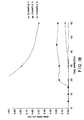
- inventive gaskets of Examples 1, 3, 4 and 7 it can also be seen in Figure 14 that the leak rate decreased with increase in thickness of the full density ePTFE substantially air impermeable layers 14.
- inventive gaskets of Examples 1, 3, 4 and 7 they all have the same inner and outer diameter dimensions with the same location of the substantially air impermeable region 13.
- the substantially air impermeable layers 14 are all full density expanded PTFE. The differences between them are the thickness levels of the substantially air impermeable layers 14, with the thicker substantially air impermeable layers 14 being more highly air impermeable than the thinner substantially air impermeable layers 14.
- Example 3 representing the inventive embodiment shown in Figures 1 - 3.
- This gasket had the air impermeable region located between the inner and outer diameter of the gasket.
- a desired advantage in this embodiment is that upon migration of fluid into the expanded PTFE layer 15 of first chamber 11, and upon subsequent blockage of further fluid permeation by substantially air impermeable region 13, the fluid that is "trapped" in first chamber 11 exerts an outward force against substantially air impermeable layers 14. It is believed that this phenomenon helps to further conform and seal substantially air impermeable layers 14 to the surfaces of the flanges, thereby improving the seal by gasket 10.
- second chamber 12 helps to provide a resistant force behind substantially air impermeable region 13 that helps prevent rupture of substantially air impermeable region 13.
- Example 5 representing the inventive gasket shown in Figures 4-6. This gasket had the substantially air impermeable region 13 located at the inner diameter of the gasket.
- Example 8 representing the inventive gasket shown in Figures 7-9. This gasket had the substantially air impermeable region 13 located at the outer diameter of the gasket.
- Example 5 Example 3 Reading Time (min) Manometer Reading (inches) LeakRate (mL/hr) Reading Time (min) Manometer Reading (inches) LeakRate (mL/hr) 1 5 0.00 0.00 1 5 0.00 0.00 2 10 0.00 0.00 2 10 0.00 0.00 3 15 0.00 0.00 3 15 0.00 0.00 4 20 0.05 0.15 4 20 0.00 0.00 5 30 0.08 0.15 5 30 0.00 0.00 6 45 0.15 0.19 6 60 0.05 0.05 7 60 0.18 0.17 Average Leak Rate: 0.09 Average Leak Rate: 0.01
- the test fixture 100 consists of a set of 2-inch X 150 lb class blind steel flanges 101 having a surface finish of RMS 32, tightened together with four 5/8 inch bolts 102. In one of the flanges 101 an air inlet port 103 is drilled such that an air inlet connecting means can be attached to pressurize the assembly from the internal diameter of the tested gasket.
- Gasket stress (psi) gasket stress (psi) * 0.00689476
- the tightened gasket / flange assembly was then pressurized at the first desired constant air pressure (30 psi) or (0.21 MPa).
- the gasket / flange assembly was then sprayed with a soapy water solution.
- the gasket / flange assembly was then visually checked for bubbles appearing in the soapy water along the outer diameter of the gasket 104 indicating air leakage. If a leak is present, the soapy water bubbles will appear, indicating the transmission of air passing around and / or through the gasket 104.
- the internal air pressure was increased to the next level (60 psi) or (0.41 MPa). Again, after determining whether or not there were air bubbles present at this pressure level, the internal air pressure was increased to the final level (90 psi) or (0.62 MPa), where once again it was determined whether or not air bubbles were present. The internal air pressure was then released.
- the flange / gasket assembly was then tightened to the next level (500 psi) or (3.45 MPa) in three evenly divided increments as done before in a crossing type pattern.
- the bubble test was then conducted as explained above for each internal air pressure level, with the only difference being there was a fifteen minute wait before applying the first internal air pressure level instead of a ten minute wait.
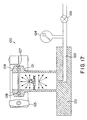
- the air permeability test fixture 120 was created using a 1.5 inch (3.81 cm) diameter sanitary flange ferrule 121.
- the ferrule 121 was cut to a length of 5.2 cm and welded to a stainless steel base 122.
- a hole 123 was drilled through the base for connection to a pressurized air source and pressure measurement instrumentation. All components of the test fixture 120 were connected using 1/8 inch tubing and compression fittings.
- a digital manometer 124 (350 Smart Manometer commercially available from Meriam Instrument of Cleveland, Ohio) was used to accurately measure pressure.
- a regulated air supply was used to pressurize the test fixture to the proper starting pressure.
- a shut off valve 126 connected with compression fittings, was used to block airflow to or from the test fixture once the desired internal pressure was achieved.
- the overall internal air volume of the test fixture 120 was based on the internal air volume of the fixture 120 including the volume associated with fittings and tubing sections between the shut-off valve 126 and the interior of the flange ferrule 121.
- the total fixture volume (chamber + volume in tubing and fittings) was calculated to be 50 cubic centimeters ( ⁇ 0.5 cc).
- the sample 127 was cut into a circle having a diameter of 5.1 mm (2.0 inches). The film 127 was placed over the opening of the sanitary flange ferrule 121.
- a 1.5 inch (3.81 cm) short weld sanitary flange ferrule 129 was placed on top of the screened EPDM gasket 128 and the sanitary flange clamp 125 was tightened into place, creating a seal between the flange ferrule 121, the film sample 127, the screened EPDM gasket 128, and the short weld sanitary flange ferrule 129.
- the regulated air supply connected to the valve 126 was used to create the initial internal pressure of the test fixture 120.
- the fixture 120 was pressurized to a pressure of 50.0 kPa and the valve 126 was closed.
- a stopwatch was used to measure the time required for the pressure within the test fixture 120 to drop from 50.0 kPa to 10.0 kPa as a result of air permeation through the film test sample 127. For highly impermeable film samples (where the internal fixture pressure requires greater than ten minutes to fall from 50.0 kPa to 10.0 kPa) the pressure was recorded after 10 minutes. Table IV below shows the air impermeability results using the test procedures described above for various film type samples. Three test samples were made and tested for each film type sample. The following film type samples were tested.
- Film Type Sample A The 0.01 mm (0.0004 in) thick non-porous (full density) expanded PTFE film was produced by peeling one of the non-porous expanded PTFE outer layers from the sheet that was cut from the mandrel in Example 4. Three circles having a diameter of 5.1 mm were cut from this film to produce the test samples.
- Film Type Sample B The 0.025 mm (0.001 in) thick non-porous (full density) expanded PTFE film was produced by peeling one of the non-porous expanded PTFE outer layers from the sheet that was cut from the mandrel in Example 1. Three circles having a diameter of 5.1 mm were cut from this film to produce the test samples.
- Film type sample H represented a single layer of the microporous expanded PTFE film which was used to generate the microporous expanded PTFE inner layer 15 of some of the inventive examples.
- Film type examples I and J represented commercially available microporous expanded PTFE sheet gasketing.
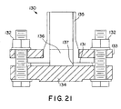
- the ink test fixture 130 shown in Figure 21 consists of a 3 inch x 150 Ib class PVDF pipe flange 135 with back up ring 133, a blind 3 inch x 150 Ib class FRP flange 134 tightened together with four lubricated 5/8 inch bolts 132.
- the gasket 131 to be tested was placed between the flanges 135 and 134 of the test fixture 130. The bolts were tightened in a crossing type pattern to a torque of 35 ft-Ibs (47.5 N-m).
Landscapes
- Engineering & Computer Science (AREA)
- General Engineering & Computer Science (AREA)
- Mechanical Engineering (AREA)
- Gasket Seals (AREA)
- Manufacture Of Porous Articles, And Recovery And Treatment Of Waste Products (AREA)
Claims (32)
- Mehrschichtige, einheitliche Dichtung (10) umfassend:mindestens eine innere Schicht (15) aus gerecktem PTFE, die angeordnet ist zwischen;einer ersten im wesentlichen luftundurchlässigen äußeren Schicht (14); undeiner zweiten im wesentlichen luftundurchlässigen äußeren Schicht (14); undeinen im wesentlichen luftundurchlässigen Bereich (13), der eine Brücke zwischen der ersten und der zweiten im wesentlichen luftundurchlässigen Schicht (14) bildet.
- Mehrschichtige, einheitliche Dichtung (10) gemäß Anspruch 1, wobei die mindestens eine innere Schicht (15) aus gerecktem PTFE eine innenseitige Kante und eine außenseitige Kante besitzt.
- Mehrschichtige, einheitliche Dichtung (20) gemäß Anspruch 2, wobei der im wesentlichen luftundurchlässige Bereich (13) an der innenseitigen Kante liegt.
- Mehrschichtige, einheitliche Dichtung (30) gemäß Anspruch 2, wobei der im wesentlichen Luftundurchlässige Bereich (13) an der außenseitigen Kante liegt.
- Mehrschichtige, einheitliche Dichtung (10) gemäß Anspruch 2, wobei der im wesentlichen luftundurchlässige Bereich (13) zwischen der innenseitigen Kante und der außenseitigen Kante liegt.
- Mehrschichtige, einheitliche Dichtung (10) gemäß Anspruch 1, wobei der im wesentlichen luftundurchlässige Bereich verdichtetes gerecktes PTFE umfasst.
- Mehrschichtige, einheitliche Dichtung (10) gemäß Anspruch 1, wobei der im wesentlichen luftundurchlässige Bereich (13) gerecktes PTFE umfasst, das eine Struktur aus miteinander verbundenen Passagen und Durchgängen und einen Füllstoff besitzt, der in zumindest einem Teil der Passagen und Durchgänge vorhanden ist.
- Mehrschichtige, einheitliche Dichtung (10) gemäß Anspruch 7, wobei der Füllstoff ein Elastomer ist.
- Mehrschichtige, einheitliche Dichtung (10) gemäß Anspruch 7, wobei der Füllstoff ein Fluorelastomer ist.
- Mehrschichtige, einheitliche Dichtung (10) gemäß Anspruch 7, wobei der Füllstoff ein Perfluorelastomer ist.
- Mehrschichtige, einheitliche Dichtung (10) gemäß Anspruch 7, wobei der Füllstoff ein Perfluorpolyether-Silikonelastomer ist.
- Mehrschichtige, einheitliche Dichtung (10) gemäß Anspruch 1, wobei die erste und die zweite im wesentlichen luftundurchlässige Schicht verdichtetes, gerecktes PTFE umfassen.
- Mehrschichtige, einheitliche Dichtung (10) gemäß Anspruch 1, wobei die erste und die zweite im wesentlichen luftundurchlässige Schicht geschältes PTFE umfassen.
- Mehrschichtige, einheitliche Dichtung (10) gemäß Anspruch 1, wobei die erste und die zweite im wesentlichen luftundurchlässige Schicht PTFE umfassen.
- Mehrschichtige, einheitliche Dichtung (10) gemäß Anspruch 1, wobei die erste und die zweite im wesentlichen luftundurchlässige Schicht (14) ausgewählt sind aus der aus PFA und FEP bestehenden Gruppe.
- Mehrschichtige, einheitliche Dichtung (10) gemäß Anspruch 1, wobei es mindestens zwei der inneren Schichten (15) aus gerecktem PTFE gibt, und die des weiteren eine wesentliche luftundurchlässige Schicht umfasst, die zwischen den mindestens zwei inneren Schichten (15) liegt.
- Mehrschichtige, einheitliche Dichtung (10) gemäß Anspruch 1, des weiteren umfassend eine Mehrzahl der im wesentlichen luftundurchlässigen Bereiche (13).
- Mehrschichtige, einheitliche Dichtung (10) gemäß Anspruch 1, umfassend:einen kranzförmigen Ring mit einer oberen Oberfläche, einer unteren Oberfläche, einer innenseitigen Kante, einer außenseitigen Kante und einer Achse; wobeidie erste im wesentlichen luftundurchlässige Schicht (14) auf der oberen Oberfläche liegt;die zweite im wesentlichen luftundurchlässige Schicht (14) auf der unteren Oberfläche liegt;die mindestens eine Schicht (15) aus gerecktem PTFE zwischen der ersten und der zweiten im wesentlichen luftundurchlässigen Schicht (14) liegt; undder im wesentlichen luftundurchlässige Bereich (13) eine Brücke zwischen der ersten und der zweiten im wesentlichen luftundurchlässigen Schicht (14) bildet;wobei alle der Schichten (13, 14) im wesentlichen senkrecht zu der Achse ausgerichtet sind.
- Mehrschichtige, einheitliche Dichtung (20) gemäß Anspruch 18, wobei der im wesentlichen luftundurchlässige Bereich (13) an der innenseitigen Kante des kranzförmigen Rings liegt.
- Mehrschichtige, einheitliche Dichtung (30) gemäß Anspruch 18, wobei der im wesentlichen luftundurchlässige Bereich (13) an der außenseitigen Kante des kranzförmigen Rings liegt.
- Mehrschichtige, einheitliche Dichtung (10) gemäß Anspruch 18, wobei der im wesentlichen luftundurchlässige Bereich (13) zwischen der innenseitigen Kante und der außenseitigen Kante des kranzförmigen Rings liegt.
- Mehrschichtige, einheitliche Dichtung (10) gemäß Anspruch 19, wobei zumindest eine der ersten und zweiten im wesentlichen luftundurchlässigen Schichten (14) verdichtetes gerecktes PTFE umfasst.
- Mehrschichtige, einheitliche Dichtung (10) gemäß Anspruch 20, wobei zumindest eine der ersten und zweiten im wesentlichen luftundurchlässigen Schichten (14) verdichtetes gerecktes PTFE umfasst.
- Mehrschichtige, einheitliche Dichtung (10) gemäß Anspruch 21, wobei zumindest eine der ersten und zweiten im wesentlichen luftundurchlässigen Schichten (14) verdichtetes gerecktes PTFE umfasst.
- Mehrschichtige, einheitliche Dichtung (10) gemäß Anspruch 22, wobei der im wesentlichen luftundurchlässige Bereich (13) verdichtetes gerecktes PTFE umfasst.
- Mehrschichtige, einheitliche Dichtung (10) gemäß Anspruch 23, wobei der im wesentlichen luftundurchlässige Bereich (13) ein verdichtetes gerecktes PTFE umfasst.
- Mehrschichtige, einheitliche Dichtung (10) gemäß Anspruch 24, wobei der im wesentlichen luftundurchlässige Bereich (13) ein verdichtetes gerecktes PTFE umfasst.
- Mehrschichtige, einheitliche Dichtung (10) gemäß Anspruch 1, wobei die Dichtung (10) kranzförmig ist und einen Innenumfang, einen Außenumfang, eine obere Oberfläche und eine untere Oberfläche besitzt, umfassend:eine erste Kammer (11) aus gerecktem PTFE, die angrenzend an den inneren Umfang angeordnet ist und die die erste luftundurchlässige Schicht (14) auf der oberen Oberfläche und die erste luftundurchlässige untere Schicht (14) auf der unteren Oberfläche besitzt;eine zweite Kammer (12) aus gerecktem PTFE, die angrenzend an den äußeren Umfang angeordnet ist und die zweite luftundurchlässige Schicht (14) auf der oberen Oberfläche und die zweite luftundurchlässige Schicht (14) auf der unteren Oberfläche besitzt;wobei der im wesentlichen luftundurchlässige Bereich (13) zwischen der ersten und zweiten Kammer (11, 12) liegt.
- Kranzförmige Dichtung (10) gemäß Anspruch 28, wobei der im wesentlichen luftundurchlässige Bereich (13) eine Dicke besitzt, die geringer ist, als eine Dicke der ersten und zweiten Kammer (11, 12).
- Kranzförmige Dichtung (10) gemäß Anspruch 28, verwendet in einem glasüberzogenen Stahlflansch.
- Kranzförmige Dichtung (10) gemäß Anspruch 28, verwendet in einem Glasflansch.
- Kranzförmige Dichtung (10) gemäß Anspruch 28, verwendet in einem Glasfaser verstärkten Kunststofflansch.
Applications Claiming Priority (3)
| Application Number | Priority Date | Filing Date | Title |
|---|---|---|---|
| US372122 | 1999-08-11 | ||
| US09/372,122 US6485809B1 (en) | 1999-08-11 | 1999-08-11 | Low stress to seal gasket |
| PCT/US2000/021921 WO2001011274A1 (en) | 1999-08-11 | 2000-08-11 | Low stress to seal gasket |
Publications (2)
| Publication Number | Publication Date |
|---|---|
| EP1203176A1 EP1203176A1 (de) | 2002-05-08 |
| EP1203176B1 true EP1203176B1 (de) | 2005-06-22 |
Family
ID=23466800
Family Applications (1)
| Application Number | Title | Priority Date | Filing Date |
|---|---|---|---|
| EP00953951A Expired - Lifetime EP1203176B1 (de) | 1999-08-11 | 2000-08-11 | Dichtung für geringe belastung |
Country Status (10)
| Country | Link |
|---|---|
| US (1) | US6485809B1 (de) |
| EP (1) | EP1203176B1 (de) |
| JP (3) | JP2003510526A (de) |
| KR (1) | KR100438333B1 (de) |
| CN (2) | CN100547269C (de) |
| AU (1) | AU6631200A (de) |
| CA (1) | CA2380926C (de) |
| DE (1) | DE60020974T2 (de) |
| ES (1) | ES2244463T3 (de) |
| WO (1) | WO2001011274A1 (de) |
Cited By (1)
| Publication number | Priority date | Publication date | Assignee | Title |
|---|---|---|---|---|
| DE102020116381A1 (de) | 2020-06-22 | 2021-12-23 | Kwo Dichtungstechnik-Gmbh | Dichtung |
Families Citing this family (24)
| Publication number | Priority date | Publication date | Assignee | Title |
|---|---|---|---|---|
| US20040232624A1 (en) * | 2002-03-11 | 2004-11-25 | Hirokazu Hisano | Closed annular sealing material and method for manufacturing same |
| US20040157035A1 (en) * | 2003-02-10 | 2004-08-12 | Guizzetti Allen R. | Low permeation gaskets |
| US20040173978A1 (en) | 2003-03-06 | 2004-09-09 | Christopher Bowen | PTFE membranes and gaskets made therefrom |
| US20040175571A1 (en) * | 2003-03-06 | 2004-09-09 | Wolfgang Buerger | Filled PTFE membranes and gaskets made therefrom |
| US20050124242A1 (en) * | 2003-12-03 | 2005-06-09 | Jean Norvell | Novel polymer films and textile laminates containing such polymer films |
| US7179525B2 (en) * | 2004-03-10 | 2007-02-20 | Gore Enterprise Holdings, Inc. | Low stress to seal expanded PTFE gasket tape |
| ATE441798T1 (de) | 2004-03-10 | 2009-09-15 | Gore Enterprise Holdings Inc | Dichtungsband aus expandiertem ptfe zum abdichten unter niedrigen kräften |
| MXPA06011838A (es) * | 2004-04-07 | 2007-05-04 | Garlock Sealing Technologies | Material de junta. |
| US20050225037A1 (en) | 2004-04-13 | 2005-10-13 | Dove Kevin E | Coil gasket |
| US7361398B2 (en) * | 2005-08-22 | 2008-04-22 | Gore Enterprise Holdings, Inc. | Low stress to seal ePTFE gasket material |
| US7455301B2 (en) * | 2006-03-02 | 2008-11-25 | Virginia Sealing Products, Inc. | Seamless corrugated insert gasket and method of forming the same |
| US20100253009A1 (en) * | 2007-07-09 | 2010-10-07 | Aram Corporation | Gasket for Food Processing Plant, Piping Joint Structure for Food Processing Plant Using the Gasket and O-Ring for Food Processing Plant |
| SE533541C2 (sv) * | 2009-02-04 | 2010-10-19 | Roxtec Ab | Smörjning av en rör- eller kabelgenomföring |
| US20110304105A1 (en) * | 2010-06-14 | 2011-12-15 | Li-Cor, Inc. | Diffusion and sorption free gaskets for gas exchange measurement systems |
| CA2806366C (en) | 2010-09-30 | 2016-08-09 | W.L. Gore & Associates Gmbh | Low leakage rate composite gasket |
| DE202011102722U1 (de) | 2011-03-05 | 2011-09-12 | Ddl Gmbh | Vorrichtung zum Abdichten des Ringraumes zwischen Medienrohr/Kabel und Kernbohrung/Schutzrohr |
| DE102013002753B3 (de) * | 2013-02-19 | 2014-06-05 | Fachhochschule Münster | Verfahren zur Herstellung eines Dichtungselementes |
| US9310852B2 (en) | 2013-10-03 | 2016-04-12 | Lenovo Enterprise Solutions (Singapore) Pte. Ltd. | Automatic sealing of a gap along a chassis positioned in a rack |
| CN104033608A (zh) * | 2014-06-27 | 2014-09-10 | 杨海蓉 | 一种聚四氟乙烯焊接夹层垫圈 |
| DE102015110944A1 (de) * | 2015-07-07 | 2017-01-12 | W.L. Gore & Associates Gmbh | Ringdichtung |
| CN107513271A (zh) * | 2017-08-31 | 2017-12-26 | 太仓卡斯特姆新材料有限公司 | 一种低压缩抗变形橡胶密封圈 |
| US11268616B2 (en) * | 2017-10-06 | 2022-03-08 | Virginia Sealing Products, Inc. | Envelope gasket |
| US20210024255A1 (en) * | 2019-07-23 | 2021-01-28 | Sartorius Stedim North America, Inc. | Composite Articles of Lattice Reinforced Elastomers |
| DE102019123366A1 (de) * | 2019-08-30 | 2021-03-04 | Gerhard Schadenfroh | Verfahren zur Herstellung eines Dichtrings |
Family Cites Families (66)
| Publication number | Priority date | Publication date | Assignee | Title |
|---|---|---|---|---|
| US2094908A (en) | 1934-10-26 | 1937-10-05 | Walter I Thrall | Domestic water heating and gas supply system |
| US2342647A (en) | 1941-12-26 | 1944-02-29 | Detroit Gasket & Mfg Company | Gasket |
| US2599767A (en) | 1946-04-01 | 1952-06-10 | Joe G Long | Rubber seal joint |
| US3230290A (en) | 1961-02-23 | 1966-01-18 | Shell Oil Co | Composite gasket and method of applying same |
| US3382567A (en) | 1963-08-13 | 1968-05-14 | Ind Werk Schaeffler | Method of forming and securing a sealing device in a bore |
| US3442520A (en) | 1967-08-02 | 1969-05-06 | Trw Inc | Bearing seal |
| US3679218A (en) | 1969-03-03 | 1972-07-25 | Farnam Co F D | Unitized valve plate, gaskets and the like |
| US3697348A (en) | 1969-07-09 | 1972-10-10 | Farnam Co F D | Method of making gaskets |
| US3597566A (en) | 1969-08-22 | 1971-08-03 | Cryodry Corp | Resonant cavity microwave applicator |
| US3743305A (en) | 1970-02-19 | 1973-07-03 | Federal Mogul Corp | Shaft seal with expandable outer periphery |
| SE392582B (sv) | 1970-05-21 | 1977-04-04 | Gore & Ass | Forfarande vid framstellning av ett porost material, genom expandering och streckning av en tetrafluoretenpolymer framstelld i ett pastabildande strengsprutningsforfarande |
| US3787278A (en) | 1970-05-28 | 1974-01-22 | Olin Corp | Molded multiple density polyurethane foam |
| US3863936A (en) | 1973-03-27 | 1975-02-04 | Farnam Co F D | High temperature gasket structure and method of producing same |
| US3843139A (en) | 1970-12-23 | 1974-10-22 | Garlock Inc | Oil seal |
| US3720420A (en) | 1971-03-19 | 1973-03-13 | Parker Hannifin Corp | Gasket |
| US3926445A (en) | 1972-05-04 | 1975-12-16 | Farnam Co F D | Convolutely wound gasket |
| US3854736A (en) | 1972-10-27 | 1974-12-17 | Farnam F Co | Densified convolute gasket structure |
| US4070219A (en) | 1974-08-12 | 1978-01-24 | F. D. Farnam Co. | Method of making densified convolute gasket structure |
| US4032606A (en) | 1974-09-17 | 1977-06-28 | Anatoly Vasilievich Solomatin | Method for producing solid-porous rubber articles |
| US4042747A (en) | 1975-03-14 | 1977-08-16 | Joseph A. Teti, Jr. | Gasket and sealing structures of filled polytetrafluoroethylene resins |
| US3986721A (en) | 1975-08-08 | 1976-10-19 | Eagle-Picher Industries, Inc. | Two component gasket and method of making it |
| US4082893A (en) | 1975-12-24 | 1978-04-04 | Sumitomo Electric Industries, Ltd. | Porous polytetrafluoroethylene tubings and process of producing them |
| US4234535A (en) | 1976-04-29 | 1980-11-18 | Sumitomo Electric Industries, Ltd. | Process for producing porous polytetrafluoroethylene tubings |
| JPS5572950A (en) | 1978-11-20 | 1980-06-02 | Nippon Pillar Packing Co Ltd | Ptfe-wrapped gasket |
| IT1123311B (it) | 1979-09-25 | 1986-04-30 | A T G S P A Applic Tecniche Go | Guarnizione di tenuta radiale |
| US4385093A (en) | 1980-11-06 | 1983-05-24 | W. L. Gore & Associates, Inc. | Multi-component, highly porous, high strength PTFE article and method for manufacturing same |
| ZA817843B (en) | 1980-11-15 | 1982-10-27 | T & N Materials Res Ltd | Manufacture of gaskets |
| GB2094005B (en) | 1981-02-03 | 1985-05-30 | Coal Industry Patents Ltd | Electrochemical gas sensor |
| GB2094908A (en) | 1981-03-13 | 1982-09-22 | Angus George Co Ltd | An edge seal ring |
| US4560714A (en) | 1982-12-16 | 1985-12-24 | Celanese Corporation | Water-swellable crosslinked polymeric microgel particles and aqueous dispersions of organic film-forming resins containing the same |
| US4487421A (en) | 1983-05-10 | 1984-12-11 | Hamilton Kent Manufacturing Company, Inc. | Pipe gasket with reinforcing means in its base self-energizing |
| GB8313846D0 (en) | 1983-05-19 | 1983-06-22 | City Tech | Gas sensor |
| JPS6075791A (ja) * | 1983-09-30 | 1985-04-30 | Toshiba Corp | スクロ−ル型圧縮装置 |
| DE3339018A1 (de) | 1983-10-27 | 1985-05-09 | W.L. Gore & Co GmbH, 8011 Putzbrunn | Dichtung aus mikroporoesem polytetrafluorethylen und verfahren zu deren herstellung |
| JPS6075791U (ja) * | 1983-10-31 | 1985-05-27 | ジヤパンゴアテツクス株式会社 | 配管用シ−ル形成素材 |
| IT1187210B (it) | 1985-10-31 | 1987-12-16 | Italtractor | Gruppo guarnizione anulare per tenuta frontale |
| JPS63121864A (ja) * | 1986-11-11 | 1988-05-25 | Ricoh Co Ltd | 複写機の制御装置 |
| US4676515A (en) | 1986-11-20 | 1987-06-30 | Felt Products Mfg. Co. | Composite embossed sandwich gasket with graphite layer |
| JPH0413475Y2 (de) * | 1987-02-02 | 1992-03-30 | ||
| DE8800023U1 (de) | 1988-01-04 | 1989-05-03 | Irbit Research + Consulting Ag, Freiburg/Fribourg, Ch | |
| AU3747889A (en) | 1988-05-25 | 1989-12-12 | W.L. Gore & Associates, Inc. | Gasketing products and manufacture thereof |
| US4913951A (en) | 1988-07-26 | 1990-04-03 | Garlock Inc. | Fabrication of reinforced PTFE gasketing material |
| US4900629A (en) | 1988-10-04 | 1990-02-13 | Garlock Inc. | High compressibility gasket material |
| JPH0462042A (ja) | 1990-06-25 | 1992-02-27 | Gasket Seisakusho:Yugen | 複合ガスケット材料 |
| JP2719844B2 (ja) * | 1990-07-26 | 1998-02-25 | 日本ピラー工業株式会社 | ガスケットおよびその製造方法 |
| GB9017173D0 (en) | 1990-08-06 | 1990-09-19 | Specialist Sealing Ltd | Static seal |
| US5112664A (en) | 1990-11-30 | 1992-05-12 | W. L. Gore & Associates, Inc. | Shielded gasket assembly |
| US5558347A (en) | 1990-12-31 | 1996-09-24 | Specialist Sealing Limited | Seal |
| JPH04331876A (ja) | 1991-04-30 | 1992-11-19 | Nippon Pillar Packing Co Ltd | ジャケットガスケット |
| CN2084535U (zh) * | 1991-05-08 | 1991-09-11 | 张洪庆 | 聚四氟乙烯带隔条夹层密封垫片 |
| CA2074349C (en) | 1991-07-23 | 2004-04-20 | Shinji Tamaru | Polytetrafluoroethylene porous film and preparation and use thereof |
| US5160773A (en) | 1991-08-16 | 1992-11-03 | W. L. Gore & Associates, Inc. | Encapsulated felt |
| DE69310911T2 (de) | 1992-07-20 | 1997-08-28 | Gore & Ass | Feuerfeste spiralförmige dichtung |
| US5492336A (en) | 1993-04-20 | 1996-02-20 | W. L. Gore & Associates, Inc. | O-ring gasket material and method for making and using same |
| US5551706A (en) | 1993-04-20 | 1996-09-03 | W. L. Gore & Associates, Inc. | Composite gasket for sealing flanges and method for making and using same |
| US5494301A (en) | 1993-04-20 | 1996-02-27 | W. L. Gore & Associates, Inc. | Wrapped composite gasket material |
| JPH07196831A (ja) | 1993-12-28 | 1995-08-01 | Japan Gore Tex Inc | ポリテトラフルオロエチレン多孔膜とその製造方法 |
| JP2566529B2 (ja) * | 1994-01-31 | 1996-12-25 | 日本ピラー工業株式会社 | シート状ガスケット |
| JP2905091B2 (ja) * | 1994-06-24 | 1999-06-14 | 日本バルカー工業株式会社 | フッ素樹脂被覆ガスケットの製造方法 |
| JP3576229B2 (ja) | 1994-10-24 | 2004-10-13 | 塩野義製薬株式会社 | サニタリ配管用ガスケット及びその製作方法 |
| CA2174451C (en) | 1994-10-31 | 2000-10-24 | John W. Dolan | Rigid sheet polytetrafluoroethylene material |
| JP2918791B2 (ja) * | 1994-12-26 | 1999-07-12 | 日本ピラー工業株式会社 | 多孔質ポリテトラフルオロエチレン製ガスケット |
| CA2170478A1 (en) * | 1995-03-02 | 1996-09-03 | Ross Kennedy Hutter | Improved resilient sealing gasket |
| US5476589A (en) | 1995-03-10 | 1995-12-19 | W. L. Gore & Associates, Inc. | Porpous PTFE film and a manufacturing method therefor |
| DE19706981A1 (de) | 1997-02-21 | 1998-10-15 | Gore W L & Ass Gmbh | Dichtungselement für gepackte Kolonnen |
| JP3615912B2 (ja) * | 1997-06-30 | 2005-02-02 | 愛三工業株式会社 | 内燃機関の吸気装置 |
-
1999
- 1999-08-11 US US09/372,122 patent/US6485809B1/en not_active Expired - Lifetime
-
2000
- 2000-08-11 CN CNB200610141383XA patent/CN100547269C/zh not_active Expired - Lifetime
- 2000-08-11 ES ES00953951T patent/ES2244463T3/es not_active Expired - Lifetime
- 2000-08-11 EP EP00953951A patent/EP1203176B1/de not_active Expired - Lifetime
- 2000-08-11 CN CNB008116288A patent/CN100343554C/zh not_active Expired - Lifetime
- 2000-08-11 KR KR10-2002-7001837A patent/KR100438333B1/ko active IP Right Grant
- 2000-08-11 JP JP2001515491A patent/JP2003510526A/ja active Pending
- 2000-08-11 AU AU66312/00A patent/AU6631200A/en not_active Abandoned
- 2000-08-11 WO PCT/US2000/021921 patent/WO2001011274A1/en active IP Right Grant
- 2000-08-11 CA CA002380926A patent/CA2380926C/en not_active Expired - Lifetime
- 2000-08-11 DE DE60020974T patent/DE60020974T2/de not_active Expired - Lifetime
-
2011
- 2011-08-05 JP JP2011172263A patent/JP2012007735A/ja active Pending
- 2011-08-05 JP JP2011172264A patent/JP2011257006A/ja active Pending
Cited By (1)
| Publication number | Priority date | Publication date | Assignee | Title |
|---|---|---|---|---|
| DE102020116381A1 (de) | 2020-06-22 | 2021-12-23 | Kwo Dichtungstechnik-Gmbh | Dichtung |
Also Published As
| Publication number | Publication date |
|---|---|
| JP2012007735A (ja) | 2012-01-12 |
| DE60020974D1 (de) | 2005-07-28 |
| ES2244463T3 (es) | 2005-12-16 |
| US6485809B1 (en) | 2002-11-26 |
| CN1370259A (zh) | 2002-09-18 |
| CN100343554C (zh) | 2007-10-17 |
| KR20020021686A (ko) | 2002-03-21 |
| WO2001011274A1 (en) | 2001-02-15 |
| JP2011257006A (ja) | 2011-12-22 |
| CN1940357A (zh) | 2007-04-04 |
| CA2380926C (en) | 2007-07-17 |
| CN100547269C (zh) | 2009-10-07 |
| EP1203176A1 (de) | 2002-05-08 |
| CA2380926A1 (en) | 2001-02-15 |
| DE60020974T2 (de) | 2006-08-17 |
| AU6631200A (en) | 2001-03-05 |
| KR100438333B1 (ko) | 2004-07-02 |
| JP2003510526A (ja) | 2003-03-18 |
Similar Documents
| Publication | Publication Date | Title |
|---|---|---|
| EP1203176B1 (de) | Dichtung für geringe belastung | |
| JP5015932B2 (ja) | 低シール応力のePTFEガスケット材料 | |
| US4900629A (en) | High compressibility gasket material | |
| PL188472B1 (pl) | Uszczelka płaska z tworzywa warstwowego | |
| EP0416031B1 (de) | Dichtung | |
| KR100190439B1 (ko) | 그랜드패킹 | |
| WO2001027501A1 (en) | Low stress to seal form-in-place gasket | |
| US6268020B1 (en) | Method of fabricating high sealing gaskets | |
| EP2754927B1 (de) | Verbunddichtung mit niedriger Leckrate | |
| US20030003290A1 (en) | Sealing material in the form of tape, and production thereof | |
| CA2585724C (en) | Low stress to seal gasket | |
| US20190107200A1 (en) | Envelope Gasket | |
| AU2010361325B8 (en) | Low leakage rate composite gasket | |
| GB2363172A (en) | A process for preparing high sealing gaskets |
Legal Events
| Date | Code | Title | Description |
|---|---|---|---|
| PUAI | Public reference made under article 153(3) epc to a published international application that has entered the european phase |
Free format text: ORIGINAL CODE: 0009012 |
|
| 17P | Request for examination filed |
Effective date: 20020219 |
|
| AK | Designated contracting states |
Kind code of ref document: A1 Designated state(s): AT BE CH CY DE DK ES FI FR GB GR IE IT LI LU MC NL PT SE |
|
| AX | Request for extension of the european patent |
Free format text: AL;LT;LV;MK;RO;SI |
|
| RIN1 | Information on inventor provided before grant (corrected) |
Inventor name: EGRES, RONALD, G., JR. Inventor name: DOVE, KEVIN Inventor name: MINOR, RAYMOND, B. Inventor name: MILLS, DAVID, J. Inventor name: RIEDL, ALEXANDER Inventor name: HISANO, HIROKAZU |
|
| RAP1 | Party data changed (applicant data changed or rights of an application transferred) |
Owner name: W.L. GORE & ASSOCIATES GMBH Owner name: JAPAN GORE-TEX, INC. Owner name: GORE ENTERPRISE HOLDINGS, INC. |
|
| 17Q | First examination report despatched |
Effective date: 20040213 |
|
| RBV | Designated contracting states (corrected) |
Designated state(s): DE ES FR GB IT |
|
| GRAP | Despatch of communication of intention to grant a patent |
Free format text: ORIGINAL CODE: EPIDOSNIGR1 |
|
| GRAS | Grant fee paid |
Free format text: ORIGINAL CODE: EPIDOSNIGR3 |
|
| GRAA | (expected) grant |
Free format text: ORIGINAL CODE: 0009210 |
|
| AK | Designated contracting states |
Kind code of ref document: B1 Designated state(s): DE ES FR GB IT |
|
| REG | Reference to a national code |
Ref country code: GB Ref legal event code: FG4D |
|
| REF | Corresponds to: |
Ref document number: 60020974 Country of ref document: DE Date of ref document: 20050728 Kind code of ref document: P |
|
| RAP2 | Party data changed (patent owner data changed or rights of a patent transferred) |
Owner name: GORE ENTERPRISE HOLDINGS, INC. Owner name: JAPAN GORE-TEX, INC. Owner name: W.L. GORE & ASSOCIATES GMBH |
|
| REG | Reference to a national code |
Ref country code: ES Ref legal event code: FG2A Ref document number: 2244463 Country of ref document: ES Kind code of ref document: T3 |
|
| ET | Fr: translation filed | ||
| PLBE | No opposition filed within time limit |
Free format text: ORIGINAL CODE: 0009261 |
|
| STAA | Information on the status of an ep patent application or granted ep patent |
Free format text: STATUS: NO OPPOSITION FILED WITHIN TIME LIMIT |
|
| 26N | No opposition filed |
Effective date: 20060323 |
|
| REG | Reference to a national code |
Ref country code: FR Ref legal event code: PLFP Year of fee payment: 16 |
|
| REG | Reference to a national code |
Ref country code: DE Ref legal event code: R082 Ref document number: 60020974 Country of ref document: DE Representative=s name: KLUNKER, SCHMITT-NILSON, HIRSCH, DE Ref country code: DE Ref legal event code: R082 Ref document number: 60020974 Country of ref document: DE Representative=s name: KLUNKER IP PATENTANWAELTE PARTG MBB, DE Ref country code: DE Ref legal event code: R081 Ref document number: 60020974 Country of ref document: DE Owner name: W.L. GORE & ASSOCIATES GMBH, DE Free format text: FORMER OWNERS: GORE ENTERPRISE HOLDINGS, INC., NEWARK, DEL., US; W.L. GORE & ASSOCIATES GMBH, 85640 PUTZBRUNN, DE; JAPAN GORE-TEX, INC., TOKIO/TOKYO, JP Ref country code: DE Ref legal event code: R081 Ref document number: 60020974 Country of ref document: DE Owner name: JAPAN GORE-TEX, INC., JP Free format text: FORMER OWNERS: GORE ENTERPRISE HOLDINGS, INC., NEWARK, DEL., US; W.L. GORE & ASSOCIATES GMBH, 85640 PUTZBRUNN, DE; JAPAN GORE-TEX, INC., TOKIO/TOKYO, JP Ref country code: DE Ref legal event code: R081 Ref document number: 60020974 Country of ref document: DE Owner name: W.L. GORE & ASSOCIATES, INC., NEWARK, US Free format text: FORMER OWNERS: GORE ENTERPRISE HOLDINGS, INC., NEWARK, DEL., US; W.L. GORE & ASSOCIATES GMBH, 85640 PUTZBRUNN, DE; JAPAN GORE-TEX, INC., TOKIO/TOKYO, JP |
|
| REG | Reference to a national code |
Ref country code: GB Ref legal event code: 732E Free format text: REGISTERED BETWEEN 20151119 AND 20151125 |
|
| REG | Reference to a national code |
Ref country code: FR Ref legal event code: TP Owner name: W.L. GORE & ASSOCIATES, INC., US Effective date: 20160510 |
|
| REG | Reference to a national code |
Ref country code: FR Ref legal event code: PLFP Year of fee payment: 17 |
|
| REG | Reference to a national code |
Ref country code: FR Ref legal event code: PLFP Year of fee payment: 18 |
|
| REG | Reference to a national code |
Ref country code: DE Ref legal event code: R082 Ref document number: 60020974 Country of ref document: DE Representative=s name: KLUNKER IP PATENTANWAELTE PARTG MBB, DE |
|
| REG | Reference to a national code |
Ref country code: FR Ref legal event code: PLFP Year of fee payment: 19 |
|
| PGFP | Annual fee paid to national office [announced via postgrant information from national office to epo] |
Ref country code: FR Payment date: 20190722 Year of fee payment: 20 Ref country code: ES Payment date: 20190902 Year of fee payment: 20 Ref country code: IT Payment date: 20190722 Year of fee payment: 20 Ref country code: DE Payment date: 20190722 Year of fee payment: 20 |
|
| PGFP | Annual fee paid to national office [announced via postgrant information from national office to epo] |
Ref country code: GB Payment date: 20190722 Year of fee payment: 20 |
|
| REG | Reference to a national code |
Ref country code: DE Ref legal event code: R071 Ref document number: 60020974 Country of ref document: DE |
|
| REG | Reference to a national code |
Ref country code: GB Ref legal event code: PE20 Expiry date: 20200810 |
|
| PG25 | Lapsed in a contracting state [announced via postgrant information from national office to epo] |
Ref country code: GB Free format text: LAPSE BECAUSE OF EXPIRATION OF PROTECTION Effective date: 20200810 |
|
| REG | Reference to a national code |
Ref country code: ES Ref legal event code: FD2A Effective date: 20201126 |
|
| PG25 | Lapsed in a contracting state [announced via postgrant information from national office to epo] |
Ref country code: ES Free format text: LAPSE BECAUSE OF EXPIRATION OF PROTECTION Effective date: 20200812 |