EP1202068A2 - Verfahren zur Bestimmung der Ausgangskapazität einer Spannungsversorgungsvorrichtung - Google Patents
Verfahren zur Bestimmung der Ausgangskapazität einer Spannungsversorgungsvorrichtung Download PDFInfo
- Publication number
- EP1202068A2 EP1202068A2 EP01125621A EP01125621A EP1202068A2 EP 1202068 A2 EP1202068 A2 EP 1202068A2 EP 01125621 A EP01125621 A EP 01125621A EP 01125621 A EP01125621 A EP 01125621A EP 1202068 A2 EP1202068 A2 EP 1202068A2
- Authority
- EP
- European Patent Office
- Prior art keywords
- voltage
- output
- value
- capacitance
- voltage supply
- Prior art date
- Legal status (The legal status is an assumption and is not a legal conclusion. Google has not performed a legal analysis and makes no representation as to the accuracy of the status listed.)
- Withdrawn
Links
- 238000000034 method Methods 0.000 title claims abstract description 20
- 238000005259 measurement Methods 0.000 claims abstract description 42
- 230000001105 regulatory effect Effects 0.000 description 4
- 239000003990 capacitor Substances 0.000 description 3
- 230000001419 dependent effect Effects 0.000 description 3
- 238000010586 diagram Methods 0.000 description 3
- 230000003071 parasitic effect Effects 0.000 description 3
- 238000010438 heat treatment Methods 0.000 description 2
- 230000001360 synchronised effect Effects 0.000 description 2
- 238000012935 Averaging Methods 0.000 description 1
- 238000011161 development Methods 0.000 description 1
- 238000011156 evaluation Methods 0.000 description 1
- 230000002349 favourable effect Effects 0.000 description 1
- 238000000691 measurement method Methods 0.000 description 1
- 230000010355 oscillation Effects 0.000 description 1
- 238000004804 winding Methods 0.000 description 1
Images


Classifications
-
- G—PHYSICS
- G01—MEASURING; TESTING
- G01R—MEASURING ELECTRIC VARIABLES; MEASURING MAGNETIC VARIABLES
- G01R31/00—Arrangements for testing electric properties; Arrangements for locating electric faults; Arrangements for electrical testing characterised by what is being tested not provided for elsewhere
- G01R31/36—Arrangements for testing, measuring or monitoring the electrical condition of accumulators or electric batteries, e.g. capacity or state of charge [SoC]
- G01R31/385—Arrangements for measuring battery or accumulator variables
- G01R31/386—Arrangements for measuring battery or accumulator variables using test-loads
Definitions
- the invention relates to a method for determining the output capacity of a Power supply device and a power supply device and a X-ray machine with a voltage supply device.
- Power supply devices are used to supply consumers with electrical Energy, whereby a voltage supply device usually at least has two output connections and between these output connections a defined, regulated or unregulated supply voltage for the connected consumer supplies.
- high voltage supply devices are often used as switching power supplies executed. You take electrical energy from the power supply network and set it into the voltage values required for the operation of the consumer. For example must have a high voltage supply for an x-ray tube voltages in the range of deliver about 40 kV to 150 kV and currents up to 1.3 A, the tube voltage with a Controller is regulated to the required setpoint.
- an important parameter is the output capacity the power supply device.
- This parameter plays a special role when a high-voltage supply device is designed as a resonant circuit. For an optimal Regulating the output voltage, this parameter must be taken into account.
- the value of the capacitance on the output side is strongly dependent on the wiring of the Power supply device dependent. Cable capacities in particular play a role here a role.
- the output capacitance of the voltage supply device is determined by generating an unloading curve on the output side and from its course the value the output capacity is determined.
- a discharge curve is generated according to the invention by first supplying the voltage generates an output voltage to which the output capacitance is charged, and then discharge them via the RC element from the output capacitance and a measuring resistor becomes.
- the voltage generated first (first Measuring voltage value) switched off for this; however, there is a discharge curve of course, even if the voltage is only at a lower value is downshifted.
- the output capacitance is preferably determined from the course of the discharge curve by recording measured values of the voltage between the output connections at different times. In the simplest case, only two measured values are required here. In principle, one of these measured values can be the first measured voltage value (to which the output capacitance is charged at the start of the measurement). In order to achieve better accuracy, however, it is preferred to carry out the first measurement only after a waiting time has elapsed after the voltage supply has been switched off.
- the measurement is carried out on the basis of two predetermined voltage values, a starting voltage value and an end voltage value.
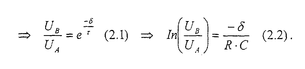
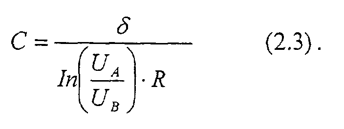
- a starting voltage value By continuously measuring the output voltage, it is first determined when the output voltage has dropped to the starting voltage value. Then the measurement continues until the final voltage value is reached. If the measuring resistor R is known and the start and end voltage values U A and U B are fixed, the capacitance C can be calculated in a very simple manner. This is because the time difference is proportional.
- two points in time (preferably after a waiting period has expired) be fixed, the voltage being measured at these fixed times and from it the capacity is calculated on the basis of the mathematically known course. But this is numerically complex due to the required logarithm calculation.
- the exact knowledge of the value of the measuring resistor also influences the accuracy of the capacitance measurement.
- high-precision resistances device below 17% is provided as a voltage divider. Because from that through Voltage supply device generated high voltage is usually only one divided share measured. It is particularly advantageous that both the many high voltage supply devices provided voltage dividers as well the voltage measuring devices also provided to determine the Output capacity can be used. So there is no external wiring or attachment of measuring devices required. Rather, the measurement by the device can be complete happen automatically, with a control device the Power supply device controls accordingly. With one Control device can be any means known to those skilled in the art act, for example a microprocessor controller.
- Power supply devices usually include connection devices for a consumer, especially plugs and cables.
- the implementation is particularly advantageous of the measuring method according to the invention with connected Connecting devices. Because especially connected cables influence through their Cable capacity, the value of the output capacity sought.
- the voltage is even when the consumer is connected can be carried out.
- the measurement must be falsified by this the consumer is either excluded or excluded. If it is the consumer is an X-ray tube, this can be achieved by the The filament of the tube is de-energized so that no current can flow in the tube. In the In practice, however, it should be noted that it is - even without cathode heating - at high Voltage values can lead to electrode emission (cold emission). The expert will make sure that the measurement is carried out at voltages at where there is no annoying cold emission.
- An X-ray device comprises at least one X-ray tube and one Power supply device with a device for automatic determination the output capacity. The exact determination of the Output capacity for the necessary high-precision control of the output voltage from great importance.
- Fig. 1 is a circuit for an X-ray device with an X-ray tube 10 and Power supply circuit 12 shown.
- the voltage supply circuit 12 is constructed as a load-resonant converter. It comprises a transformer 14 to which the two converters 16, 18 are connected on the primary side. Secondary are on the Transformer 14 connected to the rectifier bridges 18, 20, their output connections 22, 24 on the one hand with the anode 26 and the cathode 28 of the X-ray tube 10 and on the other hand are connected to ground.
- the generation of the high voltage U 12 between the output connections 22, 24 takes place as follows:
- the converters 16, 18 run synchronized and supply, fed by the mains voltage (not shown), the voltages U 1 and U 2 on the primary side of the transformer 14
- Transformer 14 transforms the lower input voltage into a high voltage.
- the secondary side of the high-voltage transformer 14 has four taps, each of the rectifier bridges 18, 20 being connected to two taps.
- the secondary AC voltage (high voltage) of the transformer 14 is rectified by the rectifier bridges 18, 20.
- Their output voltages U 1 , U 2 are symmetrical to the ground potential, that is to say the anode voltage U 1 has the same voltage magnitude as the cathode voltage U 2 compared to the ground potential.
- the voltage dividers 30, 32 from the measuring resistors 34, 36, 38, 40 are connected between the output connections 22, 24 and the ground potential.
- the voltage dividers 30, 32 each serve to divide the anode voltage U 1 and the cathode voltage U 2 down to the significantly lower voltages U 1 'and U 2 '.
- the resistors meet high accuracy requirements; they have a deviation of less than 1%.
- the output capacitances C d1 and C d2 are also shown in the circuit diagram between the output connections 22, 24 and the ground potential. In practice, these are not discrete components. Instead, these capacitances occur as parasitic capacitances, especially as cable capacitances of the connecting cable with which the x-ray tube 10 is connected to the voltage supply circuit 12 (not shown).
- the capacitances C d1 and C d2 serve in the voltage supply circuit 12 as buffer capacitances for the output voltages U 1 , U 2 .
- the voltage supply circuit 12 works as a load resonant overall Inverter.
- the primary circuit is determined by the leakage inductance of the transformer 14 and resonance capacitors 17 added to a series resonance circuit.
- the secondary-side winding capacitance of the high-voltage transformer 14 extends the Load circuit to a series-parallel-resonant resonance circuit.
- the working frequency of the Synchronized converter 16, 18 is selected so that it is close to the natural resonance frequency of the load circuit. This will reduce the voltage drop across the impedance of the Resonance circuit minimal.
- the voltage supply circuit 12 with two inverters 16, 18 and two rectifier bridges 18, 20, which are symmetrical to the earth potential, is of course not absolutely the only possible structure of such a circuit.
- only one converter and / or only one rectifier bridge can also be provided his.
- the primary and / or the secondary side is the one in FIG. 1 Circuit shown only one of the identical upper and lower parts of the Circuit available.
- the X-ray device In the operation of the X-ray device, a very fast and highly precise control of the high voltage U 12 between anode 26 and cathode 28 of the X-ray tube 10 is required.
- the rise time ie the time between reaching 10% and reaching 90% of the nominal voltage
- the X-rays generated at lower voltages do not contribute to the image quality, but only increase the radiation exposure of the patient.
- the inverters 16, 18 are controlled in such a way that a voltage U 12 of approximately 40 kV is set on the output side.
- the accuracy with which this first measurement voltage value is reached is not critical. Because the actual measurement only takes place in the middle area of the discharge curve.
- a time period t delay is initially waited until parasitic oscillations on the primary and secondary sides of the transformer 14 have subsided. Only after this period is it ensured that no further energy is supplied to the output circuit.
- the voltage U 12 is now measured continuously, a start voltage value U A and an end voltage value U B being specified which differ sufficiently from one another and are both below the first measurement voltage value of 40 kV.
- U A is larger than U B.
- the values are preferably selected such that they lie within the ranges from 10% to 90% of the maximum voltage of the discharge curve.
- the person skilled in the art will take into account that the measurement is evaluated by a controller with a signal processor. The operator must be able to process the measurements quickly enough. However, since the time interval between the measurement points U A and U B depends on the capacitance C (the distance being very short at a very low C), it should be ensured that the measurement is still carried out and processed for all expected capacitance values C. can.
- the voltage value U 12 is averaged over a digital filter, so that interference can be filtered out and the measurement is not influenced thereby. Averaging over 8 measured values has proven itself in practice.
- the times t A and t B are recorded at which the voltage U 12 reaches or falls below the predetermined start and end voltage values U A and U B.
- the x-ray device the power supply circuit 12 of which is shown in FIG. 1, has one Control device (not shown) that performs this measurement automatically.
- the heating cathode of the X-ray tube 10 is also controlled by the control device. While performing a capacitance measurement, the cathode 28 is the x-ray tube 10 unheated so that no electrodes emerge and no current in the tube 10 flows. Thus, the measurement is carried out with the tube connected and can do all Consider connection and cable capacities.
- the control device of the x-ray device is a microprocessor control, which is also coupled to the measuring device (also not shown) for the voltages U 1 'and U 2 '. Since the controller of the x-ray device is digitally implemented on this microprocessor control and as such carries out the control of the converters 16, 18 and evaluates the voltage measured values U 1 'and U 2 ', the control of the automatic measurement process by the microprocessor can also be carried out in a simple manner Control are taken over.
- a program running thereon takes over the corresponding control of the voltage supply circuit 12 and the evaluation of the voltage measurements U 1 'and U 2 ' with determination of the value for the time difference ⁇ as described above. Since the size of the resistors 34, 36, 38, 40 is fixed and known for a particular device and since the start and end voltage value U A , U B is also fixed for each device, the calculation of the capacitance value C is limited to the division ⁇ / K or (numerically more advantageous) the multiplication with the reciprocal of K.
- a voltage supply circuit 12 supplies a voltage supply circuit 12 several x-ray tubes.
- the X-ray tubes are each via cable of different lengths coupled to the voltage supply circuit 12. With help a selector switch one of the X-ray tubes is selected and with the Output terminals 22, 24 connected.
- the value for the capacitances C d1 and C d2 varies depending on the connected X-ray tube. An automatic capacity measurement is therefore carried out at least after every configuration change.
Landscapes
- Physics & Mathematics (AREA)
- General Physics & Mathematics (AREA)
- X-Ray Techniques (AREA)
- Measurement Of Resistance Or Impedance (AREA)
Abstract
Description
Die Ermittlung der Ausgangskapazität aus dem Verlauf der Entladekurve geschieht bevorzugt über die Aufnahme von Messwerten der Spannung zwischen den Ausgangsanschlüssen zu verschiedenen Zeitpunkten. Im einfachsten Fall sind hier nur zwei Messwerte erforderlich. Einer dieser Messwerte kann zwar prinzipiell der erste Messspannungswert sein (auf den die Ausgangskapazität zu Beginn der Messung aufgeladen wird). Um eine bessere Genauigkeit zu erzielen wird aber bevorzugt, die erste Messung erst nach Ablauf einer Wartezeit nach Ausschalten der Spannungsversorgung durchzuführen.
- Fig. 1
- ein Schaltbild einer Hochspannungs-Versorgung für eine Röntgenröhre;
- Fig. 2
- ein Diagramm der Entladekurve der Ausgangskapazität über einen Messwiderstand.
- Ansteuerung der Spannungsversorgungsschaltung 12 so, dass eine Ausgangsspannung U12 eines Messspannungswertes von beispielsweise 40 kV erzeugt wird.
- Abschalten des Umrichters, so dass keine weitere Spannungsversorgung erfolgt und sich die auf den Messspannungswert (40 kV) aufgeladenen Ausgangskapazitäten Cd1 und Cd2 über die Messwiderstände 34, 36, 38, 40 entladen.
- Beobachtung der Entladekurve durch Messung der Spannungen U1 und U2 (bzw. Messung der heruntergeteilten Spannungen U1' und U2') zu verschiedenen Zeitpunkten.
- Ermittlung der Kapazitätswerte Cd1 und Cd2 (aus den gemessenen Werten).

Claims (13)
- Verfahren zur Bestimmung der Ausgangskapazität einer Spannungsversorgungsvorrichtung (12),bei dem eine Ausgangsspannung (U12) in Höhe eines vorgegebenen ersten Messspannungswerts erzeugt wird,und danach die Spannungsversorgung abgeschaltet wird oder auf einen niedrigeren zweiten Messspannungswert heruntergeschaltet wird,so dass sich die Ausgangskapazität (Cd1, Cd2) über mindestens einen in der Spannungsversorgungsvorrichtung vorgesehenen Messwiderstand (34, 36, 38, 40) entlädt, wobei aus der Entladekurve der Kapazitätswert der Ausgangskapazität (Cd1, Cd2) ermittelt wird.
- Verfahren nach Anspruch 1,bei dem die Kapazitätsbestimmung automatisch durchgeführt wird,wobei eine Steuervorrichtung die Spannungsversorgungsvorrichtung (12) entsprechend steuert,und eine Messvorrichtung so steuert, dass Messwerte der Entladekurve aufgenommen werden,und aus den aufgenommenen Messwerten den Kapazitätswert (Dd1, Cd2) bestimmt.
- Verfahren nach Anspruch 1 oder 2,bei dem aus der Entladekurve der Kapazitätswert der Ausgangskapazität (Cd1, Cd2) ermittelt wird,indem die Zeitdifferenz (δ) zwischen dem Erreichen oder Unterschreiten eines vorgegebenen Startspannungswerts (UA) und dem Erreichen oder Unterschreiten eines vorgegebenen Endspannungswerts (UB) gemessen wird,und der Kapazitätswert berechnet wird aus der Zeitdifferenz (δ), dem Startspannungswert (UA), dem Endspannungswert (UB) und dem Widerstandswert des Messwiderstands oder der Messwiderstände (34, 36, 38, 40).
- Verfahren nach Anspruch 1 oder 2,bei dem aus der Entladekurve der Kapazitätswert der Ausgangskapazität (Cd1, Cd2) ermittelt wird,indem zu mindestens zwei festgelegten Zeitpunkten jeweils die Ausgangsspannung gemessen wirdund die Spannungsdifferenz ermittelt wirdund der Kapazitätswert berechnet wird aus der Spannungsdifferenz, den mindestens zwei Messpunkten und dem Widerstandswert des Messwiderstands oder der Messwiderstände (34, 36, 38, 40).
- Verfahren nach einem der vorangehenden Ansprüche,
bei dem die Messung erst nach Ablauf einer vorbestimmten Wartezeit (tdelay) nach Abschalten der Spannungsversorgung beginnt. - Verfahren nach einem der vorangehenden Ansprüche,
bei dem die Bestimmung stattfindet, während eine Anschlussvorrichtung, insbesondere Stecker und/oder Kabel für den Anschluss einer Last an die Spannungsversorgungsvorrichtung (12) angekoppelt sind. - Verfahren nach einem der vorangehenden Ansprüche,
bei dem die Messwiderstände, über die sich die Spannung entlädt, mindestens einen Spannungsteiler (30, 32) aus mindestens zwei Widerständen (34, 36; 38, 40) bilden, und die heruntergeteilte Spannung (U1', U2'), über mindestens einen der Widerstände (36, 38) des Spannungsteilers (30, 32) gemessen wird. - Verfahren nach einem der Ansprüche 1 bis 7 zur Bestimmung der ausgangsseitigen Kapazität einer Hochspannungsversorgungsvorrichtung für eine Röntgenröhre (10), bei dem die Röntgenröhre (10) während der Messung an die Hochspannungsversorgung (12) angeschlossen ist,
wobei aber kein Strom durch die Röhre (10) fließt. - Spannungsversorgungsvorrichtung mitgekennzeichnet durcheiner Spannungsversorgungseinheit, insbesondere einer Hochspannungsversorgungseinheit (12), mit mindestens zwei Ausgangsanschlüssen (22, 24)und mindestens einem Messwiderstand (34, 36, 38,40), der zwischen die Ausgangsanschlüsse (22, 24) geschaltet ist,eine Vorrichtung zur automatischen Bestimmung der Ausgangskapazität,wobei die Vorrichtung eine Spannungsmessvorrichtung für die Spannung (U12) zwischen den Ausgangsanschlüssen (22, 24) aufweist,und Mittel zur Ansteuerung der Spannungsversorgungseinheit, so dass eine Spannung (U12) zwischen den Ausgangsanschlüssen (22, 24) erzeugt wird und die Spannungsversorgungseinheit danach abgeschaltet oder auf einen niedrigeren Spannungswert heruntergeschaltet wird,sowie Mitteln zur Bestimmung der Ausgangskapazität aus der Messung der Spannung (U12) zwischen den Ausgangsanschlüssen zu mindestens zwei Zeitpunkten (tA, tB) während der Entladung über den Messwiderstand (34, 36, 38, 40).
- Spannungsversorgungsvorrichtung nach Anspruch 9,bei der die Spannungsversorgungseinheit ein lastresonanter Umrichter (12), insbesondere mit Gleichspannungsausgang ist,bei dem die Ausgangskapazität die Resonanzfrequenz mitbestimmt.
- Spannungsversorgungsvorrichtung nach Anspruch 9 oder 10,
bei der mindestens eine Anschlussvorrichtung, insbesondere Kabel und/oder Stecker zum Anschluss einer Last vorgesehen ist. - Röntgengerät mit einer Spannungsversorgungsvorrichtung nach einem der Ansprüche 9 bis 11.
- Röntgengerät nach Anspruch 12,
bei der mehrere Röntgenröhren (10) durch Kabel mit der Spannungsversorgungsvorrichtung (12) verbunden sind.
Applications Claiming Priority (2)
| Application Number | Priority Date | Filing Date | Title |
|---|---|---|---|
| DE10053279 | 2000-10-27 | ||
| DE10053279A DE10053279A1 (de) | 2000-10-27 | 2000-10-27 | Verfahren zur Bestimmung der Ausgangskapazität einer Spannungsversorgungsvorrichtung |
Publications (1)
| Publication Number | Publication Date |
|---|---|
| EP1202068A2 true EP1202068A2 (de) | 2002-05-02 |
Family
ID=7661248
Family Applications (1)
| Application Number | Title | Priority Date | Filing Date |
|---|---|---|---|
| EP01125621A Withdrawn EP1202068A2 (de) | 2000-10-27 | 2001-10-26 | Verfahren zur Bestimmung der Ausgangskapazität einer Spannungsversorgungsvorrichtung |
Country Status (5)
| Country | Link |
|---|---|
| US (1) | US20040056643A1 (de) |
| EP (1) | EP1202068A2 (de) |
| JP (1) | JP2002207055A (de) |
| CA (1) | CA2359883A1 (de) |
| DE (1) | DE10053279A1 (de) |
Families Citing this family (7)
| Publication number | Priority date | Publication date | Assignee | Title |
|---|---|---|---|---|
| EP1632782A1 (de) * | 2004-09-02 | 2006-03-08 | Delphi Technologies, Inc. | Verfahren und Vorrichtung zur Überwachung der Batterie |
| JP4514580B2 (ja) * | 2004-10-29 | 2010-07-28 | 中国電力株式会社 | 容量測定用表示装置 |
| DE102006019187A1 (de) * | 2006-04-21 | 2007-10-31 | Huf Hülsbeck & Fürst Gmbh & Co. Kg | Verfahren und Schaltungsanordnung zum Messen einer Kapazität |
| WO2015094272A1 (en) * | 2013-12-19 | 2015-06-25 | Otis Elevator Company | System and method for limiting over-voltage in power supply system |
| CN107251653B (zh) | 2015-02-10 | 2019-08-13 | 飞利浦灯具控股公司 | 用于向用于发射光的光装置供电的设备以及用于操作该设备的方法 |
| EP3438682B1 (de) * | 2017-08-02 | 2023-06-07 | Li.plus GmbH | Verfahren, vorrichtung und computerprogramm zur bestimmung einer impedanz einer elektrisch leitenden vorrichtung |
| CN109633283B (zh) * | 2019-01-31 | 2021-10-01 | 科华数据股份有限公司 | 母线电容容值监测方法、装置及终端设备 |
-
2000
- 2000-10-27 DE DE10053279A patent/DE10053279A1/de not_active Withdrawn
-
2001
- 2001-10-24 CA CA002359883A patent/CA2359883A1/en not_active Abandoned
- 2001-10-25 JP JP2001328231A patent/JP2002207055A/ja active Pending
- 2001-10-25 US US10/144,823 patent/US20040056643A1/en not_active Abandoned
- 2001-10-26 EP EP01125621A patent/EP1202068A2/de not_active Withdrawn
Also Published As
| Publication number | Publication date |
|---|---|
| US20040056643A1 (en) | 2004-03-25 |
| JP2002207055A (ja) | 2002-07-26 |
| DE10053279A1 (de) | 2002-05-08 |
| CA2359883A1 (en) | 2002-04-27 |
Similar Documents
| Publication | Publication Date | Title |
|---|---|---|
| EP1258978B1 (de) | Stromversorgungssystem | |
| EP3555644B1 (de) | Verfahren und bewertungseinheit zum ermitteln der restlebensdauer eines kondensators sowie system | |
| DE69610298T2 (de) | Hochspannungsschaltnetzteil mit mehreren hochspannungsgeneratoren | |
| DE102005055160B4 (de) | Regelschaltung zur Strom- und Spannungregelung in einem Schaltnetzteil | |
| DE3303223C2 (de) | ||
| EP1081839A2 (de) | Serienresonanter Konverter mit einer Regelschaltung | |
| EP1603219B1 (de) | Verfahren und Schaltung zur Leistungsfaktorkorrektur (PFC) | |
| DE2627545A1 (de) | Gesteuertes kapazitives filter fuer wirkleistungsverbraucher | |
| EP4040640A1 (de) | Verfahren zum betreiben einer vorrichtung zum drahtlosen übertragen von energie in richtung eines elektrischen verbrauchers mittels induktiver kopplung, vorrichtung und system | |
| DE4023612C2 (de) | ||
| DE69106273T2 (de) | Vorrichtung zur Speisung und Regelung des Stromes für den Kathodenglühfaden einer Röntgenröhre. | |
| EP0268043B1 (de) | Gleichspannungsversorgungsschaltung für Leuchtstofflampen | |
| WO2015197697A1 (de) | Schaltnetzteil | |
| DE102008027583B4 (de) | Schaltung für ein Netzteil zur Erzeugung einer Gleichspannung | |
| DE3310678C2 (de) | Schaltung zur Regelung der Ausgangsspannung eines elektronischen Schaltnetzteiles | |
| EP1202068A2 (de) | Verfahren zur Bestimmung der Ausgangskapazität einer Spannungsversorgungsvorrichtung | |
| DE3221851A1 (de) | Halbleiter-spannungsregler und mit einem solchen spannungsregler versehener generator fuer radiologieanwendungen | |
| EP0057910B2 (de) | Schaltung zur geregelten Speisung eines Verbrauchers | |
| DE19504271C1 (de) | Verfahren und Vorrichtung zur Impedanzmessung in Wechselstromnetzen sowie Verfahren und Vorrichtung zur Verhinderung von Inselnetzen | |
| DE19836364A1 (de) | Verfahren und Vorrichtung für die unterbrechungsfreie Stromversorgung | |
| DE3833148C2 (de) | Hochspannungserzeuger für eine Röntgenröhre | |
| DE2728563A1 (de) | Roentgendiagnostikgenerator mit einem seinen hochspannungstransformator speisenden wechselrichter | |
| EP2138015A1 (de) | Schaltungsanordnung zum betreiben mindestens einer entladungslampe und verfahren zum erzeugen einer hilfsspannung | |
| DE3500183A1 (de) | Hochspannungs-erzeugungsanordnung fuer ein roentgengeraet | |
| DE2559519B2 (de) | Vorrichtung zur Überwachung der Belastung eines Induktionskochgerätes |
Legal Events
| Date | Code | Title | Description |
|---|---|---|---|
| PUAI | Public reference made under article 153(3) epc to a published international application that has entered the european phase |
Free format text: ORIGINAL CODE: 0009012 |
|
| AK | Designated contracting states |
Kind code of ref document: A2 Designated state(s): AT BE CH CY DE DK ES FI FR GB GR IE IT LI LU MC NL PT SE TR |
|
| AX | Request for extension of the european patent |
Free format text: AL;LT;LV;MK;RO;SI |
|
| RAP1 | Party data changed (applicant data changed or rights of an application transferred) |
Owner name: PHILIPS CORPORATE INTELLECTUAL PROPERTY GMBH Owner name: KONINKLIJKE PHILIPS ELECTRONICS N.V. |
|
| RAP1 | Party data changed (applicant data changed or rights of an application transferred) |
Owner name: PHILIPS INTELLECTUAL PROPERTY & STANDARDS GMBH Owner name: KONINKLIJKE PHILIPS ELECTRONICS N.V. |
|
| STAA | Information on the status of an ep patent application or granted ep patent |
Free format text: STATUS: THE APPLICATION HAS BEEN WITHDRAWN |
|
| 18W | Application withdrawn |
Effective date: 20031110 |