EP1201593A1 - Verfahren und System zur Kompensation von Schwingungen in Aufzugskabinen - Google Patents
Verfahren und System zur Kompensation von Schwingungen in Aufzugskabinen Download PDFInfo
- Publication number
- EP1201593A1 EP1201593A1 EP01123846A EP01123846A EP1201593A1 EP 1201593 A1 EP1201593 A1 EP 1201593A1 EP 01123846 A EP01123846 A EP 01123846A EP 01123846 A EP01123846 A EP 01123846A EP 1201593 A1 EP1201593 A1 EP 1201593A1
- Authority
- EP
- European Patent Office
- Prior art keywords
- vibrations
- elevator car
- sensor
- control device
- detected
- Prior art date
- Legal status (The legal status is an assumption and is not a legal conclusion. Google has not performed a legal analysis and makes no representation as to the accuracy of the status listed.)
- Withdrawn
Links
- 238000000034 method Methods 0.000 title claims description 22
- 230000006870 function Effects 0.000 claims description 30
- 230000001133 acceleration Effects 0.000 claims description 28
- 238000012546 transfer Methods 0.000 claims description 18
- 230000009471 action Effects 0.000 claims description 6
- 238000013016 damping Methods 0.000 description 16
- 239000000725 suspension Substances 0.000 description 16
- 230000002123 temporal effect Effects 0.000 description 7
- 230000008569 process Effects 0.000 description 6
- 238000001514 detection method Methods 0.000 description 5
- 230000005540 biological transmission Effects 0.000 description 4
- 230000004913 activation Effects 0.000 description 3
- 238000013461 design Methods 0.000 description 3
- 230000000694 effects Effects 0.000 description 3
- 230000009123 feedback regulation Effects 0.000 description 3
- 238000005259 measurement Methods 0.000 description 3
- 230000003044 adaptive effect Effects 0.000 description 2
- 230000008859 change Effects 0.000 description 2
- 238000011161 development Methods 0.000 description 2
- 238000010586 diagram Methods 0.000 description 2
- 230000036962 time dependent Effects 0.000 description 2
- 238000013528 artificial neural network Methods 0.000 description 1
- 230000006399 behavior Effects 0.000 description 1
- 230000015572 biosynthetic process Effects 0.000 description 1
- 230000001447 compensatory effect Effects 0.000 description 1
- 230000008878 coupling Effects 0.000 description 1
- 238000010168 coupling process Methods 0.000 description 1
- 238000005859 coupling reaction Methods 0.000 description 1
- 238000013500 data storage Methods 0.000 description 1
- 230000003111 delayed effect Effects 0.000 description 1
- 230000008030 elimination Effects 0.000 description 1
- 238000003379 elimination reaction Methods 0.000 description 1
- 238000005516 engineering process Methods 0.000 description 1
- 230000000763 evoking effect Effects 0.000 description 1
- 230000036039 immunity Effects 0.000 description 1
- 238000012417 linear regression Methods 0.000 description 1
- 230000007257 malfunction Effects 0.000 description 1
- 238000013507 mapping Methods 0.000 description 1
- 230000003472 neutralizing effect Effects 0.000 description 1
- 230000003287 optical effect Effects 0.000 description 1
- 230000010355 oscillation Effects 0.000 description 1
- 238000012360 testing method Methods 0.000 description 1
- 230000007704 transition Effects 0.000 description 1
- 238000012795 verification Methods 0.000 description 1
Images


Classifications
-
- B—PERFORMING OPERATIONS; TRANSPORTING
- B66—HOISTING; LIFTING; HAULING
- B66B—ELEVATORS; ESCALATORS OR MOVING WALKWAYS
- B66B11/00—Main component parts of lifts in, or associated with, buildings or other structures
- B66B11/02—Cages, i.e. cars
- B66B11/026—Attenuation system for shocks, vibrations, imbalance, e.g. passengers on the same side
- B66B11/028—Active systems
Definitions
- the invention relates to the conveyance of people in Elevator cars and in particular on one method and one System for the compensation of vibrations in elevator cars according to the definition of the claims.
- the object of the present invention is now a highly effective compensation of vibrations in systems for Encourage people to achieve such that the Vibrations are not noticed by the passengers.
- low-frequency vibrations so-called Interference vibrations that are considered by passengers to be special be perceived as disturbing, be compensated.
- the invention is supposed to use common techniques and procedures of load and Passenger transportation industry to be compatible. Also supposed to existing passenger conveyor systems with the invention can be easily retrofitted.
- the invention is based on a departure from that in the prior art Technology implemented vibration compensation Elevator cars.
- the basic idea of the invention is in vibrations and especially spurious vibrations, so Detect as early as possible in order to optimize them compensate. This is done by multiple entries from time course of vibrations. For one thing Vibrations recorded where they are perceived as disturbing become, i.e. at the elevator car and the other they will recorded where they are generated, i.e. at a Interference source.
- Disruptive acceleration values are, for example, by Deviations from the plumb line or ideal line of a Guide shoe caused along guide rails.
- Disturbing pressure values are, for example, pressure fluctuations in the Airflow around the elevator car. The is advantageous Accelerometer on a guide shoe or the Pressure sensor attached to the elevator car.
- the acceleration values of the elevator car are as Actual values and the acceleration or pressure values on the Interference sources are presented as disturbance variables at the input of a Control device laid.
- Control device for the temporal course of disturbance variables and the time course of actual values, i.e. the impact of Malfunction available on the elevator car.
- the temporal Course of actual values or of disturbance variables as a time function in preferably regular Periods recorded.
- As part of this Accuracy of detection will be the time from occurrence a disruptive force and its temporal development, both at the source of interference as well as at the elevator car.
- the relationship between these time functions is shown by described a transfer function. Disturbances and Actual values are recorded in the control device according to the Transfer function evaluated.
- the transfer function is based on mechanical parameters of the Passenger conveyor system such as the empty weight of the elevator car, the hardness of suspension / damping elements, the current Position and weight of a compensation mass, the current conveyor load, the current load distribution in the Elevator car, etc. At least one of these mechanical ones Parameter is known or is preferred regular periods of time are determined and updated thus updated known. Certain mechanical parameters like the empty weight of the elevator car, the weight of the Compensation mass, the hardness of suspension / Damping elements can be used once before commissioning of the passenger conveyor system. Other mechanical Parameters such as the position of the compensation mass, the Conveying load and the load distribution in the elevator car can be determined updated.
- disturbance variables become one Feedforward control and actual values for feedback control used.
- the transfer function thus allows one targeted activation of at least one Compensation mass taking into account the known or updates known mechanical parameters of the Pedestrian conveyor system.
- the interference is caused by a Compensatory force of the opposite sign and preferably neutralized the same amount.
- the Compensation force does not necessarily have to be the same amount Disruptive force, but it should be at least as large be that due to uncompensated interference components excited vibrations not perceived by the passengers become.
- the compensation mass is moved by at least one drive. The drive will controlled by the control device via manipulated variables.
- a Feedback regulation of the acceleration of the elevator car carried out.
- a controller function is provided in the control device. It receives as Acceleration setpoint is 0 because the acceleration on the elevator car for optimal driving comfort be as low as possible.
- the actual value for this feedback regulation is one detected by at least one sensor Acceleration measurement.
- the manipulated variable of the controller function forms together with the compensating for the disturbance Compensation force the manipulated variable of the control device. in the Framework of the freely selectable accuracy of the Interference and actual values are activated Compensation mass very quickly, advantageously in Real time, there is no noticeable impact on the passenger Time delay in vibration compensation on that The vibrations are completely eliminated.
- low-frequency vibrations from 1 to 100 Hz, preferably from 2 to 20 Hz isolated by the control device.
- the low-frequency manipulated variables are targeted Compensating mass driven accordingly low frequency and eliminates interference vibrations.
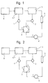
- the procedure for compensation of vibrations in Elevator cabins are based on exemplary variants schematic action plans according to Figures 1 to 4 shown.
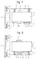
- the system for compensation of vibrations in Elevator cabs are in exemplary embodiments shown in Figures 6 to 8. Doing so Elevator car 5 by means of guide shoes 6 along Guide rails 7 out.
- the elevator car 5 is, for example. via suspension / damping elements 11 and one Catch frame 12 connected to the guide shoes 6.
- the Guide shoes 6 roll over guide rollers 6 'on the Guide rails 7.
- the suspension / damping elements 11 on the ground the elevator car 5 attached in the embodiment 7, the suspension / damping elements 11 are on Roof of the elevator car 5 attached.
- Interference sources 8 are e.g. uneven transitions from guide rails and Curvatures in the guide rails 7, causing vibrations, Centrifugal and inertial forces are generated in the elevator car 5 become.
- Interference sources 8 are, for example, via the guide rail 7 on the guide shoes 6 and from there into the elevator car 5 transferred.
- Other sources of interference 8 come from Pressure fluctuations in the air flow around the elevator car 5 forth and are transferred to the elevator car 5.
- Interference sources 8 are identified by means of at least one first sensor 1, 1 'recorded as disturbance variables Z.
- one first sensor 1 as an acceleration sensor 1 on one Guide shoe 6 attached.
- Acceleration values of the elevator cars are called actual values X recorded by at least one second sensor 2.
- a second sensor 2 as an acceleration sensor 2 on the elevator car 5, for example on the floor or on the roof of the Elevator car 5 attached.
- the effects of distracting Vibrations are therefore as close as possible to actual values X. recorded where they are perceived as disturbing, i.e. at the Elevator car 5, preferably close to the disturbing vibrations suspension / transmission to the elevator car 5 Damping elements 11.
- the time course of actual values X or of Disturbance variables Z are preferred as a time function regular periods of time recorded.
- As part of this Accuracy of detection will be the time from occurrence a disruptive force and its temporal development, both at the source of interference as well as on the elevator car 5.
- the Those skilled in the art can understand the present invention diverse variations in the detection and arrangement of Make at least one second sensor 2.
- a first one Acceleration sensor 2 is on the roof of the elevator car 5 mounted near the suspension / damping elements 11, one second acceleration sensor 2 is at the bottom of the Elevator car 5 at a distance from the suspension / Damping elements 11 mounted. This allows a spatial differentiated recording of the spread and compensation of disturbing vibrations from suspension / Damping elements 11 in the elevator car 5 by means of two Acceleration sensors 2.
- sensors 1, 1 ', 2 corresponds common industry standard, e.g. sensors 1, 1 ', 2 for example 200 measurements, preferably 20 measurements per second detected. All known sensors 1, 1 ', 2 can be used Sensor types of mechanical, optical and electrical design use.
- the embodiments shown in the figures are not mandatory, the specialist can with knowledge of present invention other positions of sensors 1, 1 ', 2 in passenger conveyor systems. For example. let yourself a pressure sensor 1 'also on the floor or on the roof of the Assemble elevator car 5. Also let slower or Use faster measuring sensors 1, 1 ', 2.
- the actual values X and disturbance variables Z are applied to the input of a control device 3.
- a control device 3 is shown in an exemplary block diagram according to FIG. 5.
- the control device 3 operates with a transfer function.
- the transfer function contains mapping rules which allow an output variable to be uniquely assigned to each input variable of the control device 3.
- the transfer function thus establishes a connection between the temporal profile of the actual values X and disturbance variables Z, the input variables at the input of the control device 3 and the temporal profile of manipulated variables Y, the output variables at the output of the control device 3.
- the transfer function is divided into a time-dependent one Controller function G R (t) and in a time-dependent interference transmission function G Z (t).
- controller function G R (t) there are the actual values X which change over time and a predetermined acceleration setpoint 0 for the acceleration of the elevator car with the value 0.
- the fault transfer function G Z (t) there are the temporary changes Z. on.
- the outputs of the controller function G R (t) and the interference transmission function G Z (t) are subtracted and thus form the outgoing manipulated variable Y that changes over time.
- the transfer function can basically be divided into two Identify species, once, if possible by all mechanical Parameters of the passenger conveyor system, which are basically are known, recorded as precisely as possible and in relation be put to each other, and the other by at least the most important of the mechanical parameters of the Passenger conveyor system with sufficient accuracy by means of of a modeling process can be estimated.
- the mechanical parameters of the passenger conveyor system are the empty weight of the Elevator car 5, the current position and the weight of the at least one compensation mass 4, the hardness of the Suspension / damping elements 11 the current conveying load, the current load distribution in the elevator car 5, etc.
- Certain mechanical parameters such as the curb weight of the Elevator car, the weight of the compensation mass 4, the Hardness of the suspension / damping elements 11 can be once before commissioning the passenger conveyor system determine.
- Other mechanical parameters such as the position of the Compensation mass, the conveying load and the load distribution updated in the elevator car are determined.
- the effort to determine the Transfer function is adaptive when using one configurable model formation processes mostly less. For example. are natural to the designer and the fitter Suspension / damping characteristics known at a certain weight of the elevator car 5 from a certain Hardness of the suspension / damping elements 11 results. However, the weight of the elevator car 5 is often not exact known. This is particularly true when installing the Passenger conveyor system to where the elevator car, for example, often not yet fully equipped, e.g. not inside is lined, and thus its empty weight only with sufficient accuracy of, for example, 10% is known.
- the model building process is successful if between the input and output variables of the Control device 3 a relationship can be established to the Effect of incoming actual values X and disturbance variables Z targeted to compensate with outgoing manipulated variables Y. It is the mechanical parameter is the basis of the Transfer function. Depending on the input and The output variables of the control device 3 become a model of the Link created which is the actual one Emulates behavior.
- actual values X are used for feedback control via the control function G R (t) and disturbance variables Z are used for a feedforward control via the interference transfer function G Z (t).
- the transfer function allows a targeted connection of at least one compensation mass 4 taking into account the known or updated known mechanical parameters of the passenger conveyor system. Targeted activation of the compensation mass 4 is understood to mean driving the compensation mass 4 attached to the elevator car 5, with the aim of countering the occurring interference force with an equal compensation force and neutralizing the interference force.
- the control device 3 specifies manipulated variables Y at least a drive 4 'of at least one to be moved Compensation mass 4 from.
- a drive 4 'of at least one to be moved Compensation mass 4 from.
- the compensation mass is advantageously 4 to 5%, preferably 2% of the permitted total weight of the Elevator car 5.
- the Compensation mass 4 linear or rotary over a Distance of +/- 10 cm, preferably +/- 5cm moved.
- the drive 4 ' is controlled by the control device 3 via the manipulated variables Y driven.
- the compensation mass 4 can periodically or aperiodically with and frequencies from 1 to 30 Hz be reduced.
- the feedback controller is advantageously whose actuator is the drive 4 ' Compensation mass 4 is, with an acceleration setpoint 0 operated.
- the drive 4 'and the compensation mass 4 the roof of the elevator car 5 arranged.
- the way of Drive the dimensioning of the to be moved Compensation mass 4 and the arrangement of drive 4 'and Compensation mass 4 with respect to the elevator car 5 can Expert with knowledge of the present invention in one freely design a wide frame.
- the at least one first sensor 1 a route profile of the elevator car 5 along the guide rail 7.
- This route profile is characteristic of the system consisting of elevator car, Guide shoes and guide rail.
- This route profile is stored in a memory 10.
- the memory 10 is of commercial design, for example electronic, magnetic respectively magneto-optical data storage.
- the saved The route profile is advantageously unique in one Verification procedure before commissioning the passenger conveyor system determined. Assuming that the route profile is temporally invariant, and with knowledge of the current Position of the elevator car 5 on the conveyor line is then permanent mounting of an acceleration sensor 1 a guide shoe 6 is not necessary.
- a Position detection is common and takes place in elevator cars For example, with a local resolution of 0.1 mm.
- disturbances Z are thus a stored route profile at the entrance the control device 3 and are with the actual values X in the control device 3 according to the transfer function evaluated.
- the route profile can be used for revisions checked and updated if necessary. Also the route profile forms a log of the state of the Systems consisting of elevator car, guide shoes and Guide rail.
- the control device 3 can have a multiple input Disturbance variables Z from several acceleration sensors 1 several guide shoes and / or more than one Detect pressure sensor 1 'on the elevator car 5. Can too the control device 3 actual values X of more than one Detect acceleration sensor 2 on the elevator car 5. Finally, the control device can have 3 manipulated variables Y. Connect several outputs to more than one drive 4 '.
- a such MIMO (multiple input multiple output) control device is, for example, as a non-linear controller, as neural network, as a fuzzy controller, as a neuro-fuzzy controller, etc. designed. With knowledge of the present invention the expert has many options for interpreting the Control device.
- low-frequency vibrations so-called interference vibrations with frequencies from 1 to 100 Hz, preferably from 2 to 20 Hz, in the control device 3, for example by means of a High pass filter with a cutoff frequency of 1 to 3 Hz isolated.
- Such low frequency vibrations are caused by usual suspension / damping elements 11 insufficient eliminated.
- Interference vibrations are however from the Passengers perceived as particularly unpleasant. about targeted control is the compensation mass with Frequencies of the interference vibrations and the Disturbing vibrations specifically eliminated.
Landscapes
- Engineering & Computer Science (AREA)
- Civil Engineering (AREA)
- Mechanical Engineering (AREA)
- Structural Engineering (AREA)
- Cage And Drive Apparatuses For Elevators (AREA)
- Elevator Control (AREA)
- Lift-Guide Devices, And Elevator Ropes And Cables (AREA)
Abstract
Description
- Figur 1
- zeigt einen Wirkungsplan einer ersten Variante mit einem Beschleunigungssensor an einem Führungsschuh,
- Figur 2
- zeigt einen Wirkungsplan einer zweiten Variante mit einem Drucksensor an der Aufzugskabine,
- Figur 3
- zeigt einen Wirkungsplan einer dritten Variante mit einem Beschleunigungssensor an einem Führungsschuh und einem Drucksensor an der Aufzugskabine,
- Figur 4
- zeigt einen Wirkungsplan einer vierten Variante mit einem Speicher zum Speichern eines Streckenprofiles,
- Figur 5
- zeigt eine Blockdarstellung der Übertragungsfunktion der Regeleinrichtung,
- Figur 6
- zeigt einen Teil einer ersten Ausführungsform eines Systems mit Aufzugskabine, Führungsschiene, Sensoren und Regeleinrichtung,
- Figur 7
- zeigt einen Teil einer zweiten Ausführungsform eines Systems mit Aufzugskabine, Führungsschiene, Sensoren und Regeleinrichtung, und
- Figur 8
- zeigt einen Teil einer dritten Ausführungsform eines Systems mit Aufzugskabine, Führungsschiene, Sensoren und Regeleinrichtung.
Claims (10)
- Verfahren zur Kompensation von Schwingungen in einer Aufzugskabine (5), unter Verwendung von mindestens einem Sensor (1, 2), welcher Sensor (1, 2) Schwingungen der Aufzugskabine (5) erfasst, einer Regeleinrichtung, welche die erfassten Schwingungen auswertet und mindestens einen Antrieb (4') zum Bewegen von mindestens einer Kompensationsmasse (4) an der Aufzugskabine (5) zur Kompensation der erfassten Schwingungen, ansteuert,
dadurch gekennzeichnet, dass über mindestens einen ersten Sensor (1, 1') Schwingungen an einer Störquelle (8) und über mindestens einen zweiten Sensor (2) Schwingungen am Auswirkungsort an der Aufzugskabine (5) erfasst werden. - Verfahren gemäss Anspruch 1, dadurch gekennzeichnet, dass vom ersten Sensor (1, 1') erfasste Schwingungen als Störgrössen (Z) an einen Eingang der Reglereinrichtung (3) gelegt werden und dass vom zweiten Sensor (2) erfasste Schwingungen als Istwerte (X) an einen Eingang der Reglereinrichtung (3) gelegt werden.
- Verfahren gemäss Anspruch 1, dadurch gekennzeichnet, dass vom ersten Sensor (1, 1') erfasste Schwingungen in einem Speicher (10) als Streckenprofil gespeichert werden und dass das Streckenprofil als Störgrössen (Z) an einen Eingang der Reglereinrichtung (3) gelegt wird und dass vom zweiten Sensor (2) erfasste Schwingungen als Istwerte (X) an einen Eingang der Reglereinrichtung (3) gelegt werden.
- Verfahren gemäss Anspruch 2 oder 3, dadurch gekennzeichnet, dass die Regeleinrichtung (3) Istwerte (X) zu einer Feedback-Regelung verwendet, dass die Regeleinrichtung (3) Störgrössen (Z) zu einer Feedforward-Regelung verwendet und dass an einem Ausgang der Regeleinrichtung (3) Stellgrössen (Y) ausgegeben werden.
- Verfahren gemäss Anspruch 1 oder 4, dadurch gekennzeichnet, dass der Antrieb (4') zum Bewegen der Kompensationsmasse (4) über Stellgrössen (Y) der Regeleinrichtung (3) angesteuert und mit einem Sollwert Null betrieben wird.
- Verfahren gemäss Anspruch 1 oder 4, dadurch gekennzeichnet, dass Schwingungen mit Frequenzen von 1 bis 100 Hz, bevorzugt von 2 bis 20 Hz in der Regeleinrichtung (3) isoliert werden und dass die Kompensationsmasse'(4) mit Frequenzen der Schwingungen angetrieben wird und die Schwingungen gezielt eliminiert werden.
- Verfahren gemäss Anspruch 1 oder 4, dadurch gekennzeichnet, dass ein Zusammenhang zwischen vom ersten Sensor (1, 1') erfassten Schwingungen und vom zweiten Sensor (2) erfassten Schwingungen über eine Übertragungsfunktion der Regeleinrichtung (3) hergestellt wird.
- System zur Kompensation von Schwingungen in einer Aufzugskabine (5), bestehend aus: mindestens einem Sensor (1, 2), welcher Sensor (1, 2) Schwingungen der Aufzugskabine (5) erfasst, einer Regeleinrichtung (3), welche die erfassten Schwingungen auswertet und mindestens einen Antrieb (4') zum Bewegen von mindestens einer Kompensationsmasse (4) an der Aufzugskabine (5) zur Kompensation der erfassten Schwingungen ansteuert, dadurch gekennzeichnet, dass mindestens ein erster Sensor (1, 1') Schwingungen an einer Störquelle (8) und mindestens ein zweiter Sensor (2) Schwingungen am Auswirkungsort an der Aufzugskabine (5) erfassen.
- System gemäss Anspruch 8, dadurch gekennzeichnet, dass die Regeleinrichtung (3) Schwingungen mit Frequenzen von 1 bis 100 Hz, bevorzugt von 2 bis 20 Hz isoliert und dass die Regeleinrichtung (3) die Kompensationsmasse (4) mit Frequenzen der Schwingungen aufschaltet und die Schwingungen gezielt eliminiert.
- System gemäss Anspruch 8 oder 9, dadurch gekennzeichnet, dass der erste Sensor (1, 1') ein Beschleunigungssensor (1) an einem Führungsschuh (6) ist bzw. ein Drucksensor (1') an der Aufzugskabine (5) ist und dass der zweite Sensor (2) ein Beschleunigungssensor (2) an der Aufzugskabine (5) ist.
Priority Applications (1)
| Application Number | Priority Date | Filing Date | Title |
|---|---|---|---|
| EP01123846A EP1201593A1 (de) | 2000-10-23 | 2001-10-05 | Verfahren und System zur Kompensation von Schwingungen in Aufzugskabinen |
Applications Claiming Priority (3)
| Application Number | Priority Date | Filing Date | Title |
|---|---|---|---|
| EP00810979 | 2000-10-23 | ||
| EP00810979 | 2000-10-23 | ||
| EP01123846A EP1201593A1 (de) | 2000-10-23 | 2001-10-05 | Verfahren und System zur Kompensation von Schwingungen in Aufzugskabinen |
Publications (1)
| Publication Number | Publication Date |
|---|---|
| EP1201593A1 true EP1201593A1 (de) | 2002-05-02 |
Family
ID=8174985
Family Applications (1)
| Application Number | Title | Priority Date | Filing Date |
|---|---|---|---|
| EP01123846A Withdrawn EP1201593A1 (de) | 2000-10-23 | 2001-10-05 | Verfahren und System zur Kompensation von Schwingungen in Aufzugskabinen |
Country Status (8)
| Country | Link |
|---|---|
| US (1) | US6494295B2 (de) |
| EP (1) | EP1201593A1 (de) |
| JP (1) | JP2002128396A (de) |
| CN (1) | CN1179873C (de) |
| AU (1) | AU782239B2 (de) |
| CA (1) | CA2359551A1 (de) |
| HK (1) | HK1046890A1 (de) |
| SG (1) | SG89424A1 (de) |
Cited By (1)
| Publication number | Priority date | Publication date | Assignee | Title |
|---|---|---|---|---|
| EP1739047A4 (de) * | 2004-04-06 | 2008-07-23 | Toshiba Elevator Kk | Dämpfungsvorrichtung für einen aufzug |
Families Citing this family (19)
| Publication number | Priority date | Publication date | Assignee | Title |
|---|---|---|---|---|
| US7503433B2 (en) * | 2003-04-07 | 2009-03-17 | Chiu Nan Wang | Elevator |
| MY138827A (en) * | 2004-02-02 | 2009-07-31 | Inventio Ag | Method for vibration damping at an elevator car |
| US7637712B2 (en) * | 2005-03-17 | 2009-12-29 | Lockheed Martin Corporation | Tray stacking and buffer system and method of use |
| WO2006100750A1 (ja) * | 2005-03-22 | 2006-09-28 | Mitsubishi Denki Kabushiki Kaisha | エレベータのかご揺すり検知装置 |
| JP4844562B2 (ja) * | 2005-06-20 | 2011-12-28 | 三菱電機株式会社 | エレベータの制振装置およびエレベータ |
| US7905332B2 (en) * | 2005-08-24 | 2011-03-15 | Otis Elevator Company | Noise control strategy for an elevator system |
| US7828122B2 (en) * | 2005-09-09 | 2010-11-09 | Mitsubishi Electric Corporation | Vibration damping device for an elevator |
| WO2009143450A2 (en) | 2008-05-23 | 2009-11-26 | Thyssenkrupp Elevator Capital Corporation | Active guiding and balance system for an elevator |
| WO2013088507A1 (ja) * | 2011-12-13 | 2013-06-20 | 三菱電機株式会社 | アクティブ動減衰器およびエレベータの振動制御方法 |
| EP3000758B1 (de) * | 2014-09-25 | 2019-04-17 | KONE Corporation | Verfahren zum auswuchten einer aufzugskabine |
| DE102014220445B4 (de) * | 2014-10-09 | 2017-06-08 | Thyssenkrupp Ag | Vorrichtung zur Überprüfung von Führungen |
| JP6399404B2 (ja) * | 2015-03-20 | 2018-10-03 | フジテック株式会社 | エレベータ用のかご横揺れ抑制装置及びかご横揺れ抑制方法 |
| JP6591923B2 (ja) * | 2016-03-30 | 2019-10-16 | 株式会社日立製作所 | エレベーター装置 |
| US10669121B2 (en) * | 2017-06-30 | 2020-06-02 | Otis Elevator Company | Elevator accelerometer sensor data usage |
| CN109095328B (zh) * | 2018-09-28 | 2020-07-31 | 山东富士制御电梯有限公司 | 一种高速电梯轿厢水平振动的减振系统及其控制方法 |
| JP2020070135A (ja) * | 2018-10-30 | 2020-05-07 | 株式会社日立製作所 | エレベーター秤装置構造 |
| CN112850405B (zh) * | 2020-12-31 | 2022-10-25 | 重庆能源职业学院 | 一种基于mems系统的电梯轿厢振动管理系统 |
| CN115636312B (zh) * | 2022-09-29 | 2026-03-27 | 上海三菱电梯有限公司 | 一种电梯轿厢自重校正方法 |
| CN118959760B (zh) * | 2024-07-26 | 2025-11-11 | 中国船舶集团有限公司第七一九研究所 | 一种减振接管主动减振方法及系统 |
Citations (4)
| Publication number | Priority date | Publication date | Assignee | Title |
|---|---|---|---|---|
| JPH05319739A (ja) * | 1992-05-20 | 1993-12-03 | Mitsubishi Electric Corp | エレベータの制振装置 |
| US5308938A (en) * | 1990-07-18 | 1994-05-03 | Otis Elevator Company | Elevator active suspension system |
| US5544721A (en) * | 1991-03-13 | 1996-08-13 | Otis Elevator Company | Method and apparatus for adjusting an elevator car based on stored horizontal displacement and acceleration information |
| US5597988A (en) * | 1994-03-31 | 1997-01-28 | Otis Elevator Company | Control system for elevator active vibration control using spatial filtering |
Family Cites Families (9)
| Publication number | Priority date | Publication date | Assignee | Title |
|---|---|---|---|---|
| JPH0388690A (ja) * | 1989-09-01 | 1991-04-15 | Hitachi Ltd | エレベータ用乗かご |
| US5294757A (en) * | 1990-07-18 | 1994-03-15 | Otis Elevator Company | Active vibration control system for an elevator, which reduces horizontal and rotational forces acting on the car |
| JP2718819B2 (ja) * | 1990-11-27 | 1998-02-25 | 株式会社東芝 | エレベータ装置 |
| JP3214050B2 (ja) * | 1991-08-07 | 2001-10-02 | 三菱電機株式会社 | エレベーターの制振装置 |
| WO1995009801A1 (en) | 1993-10-07 | 1995-04-13 | Kabushiki Kaisha Toshiba | Damping device for elevators |
| US5368132A (en) * | 1993-11-03 | 1994-11-29 | Otis Elevator Company | Suspended elevator cab magnetic guidance to rails |
| ATE201380T1 (de) * | 1995-03-10 | 2001-06-15 | Inventio Ag | Einrichtung und verfahren zur schwingungsdämpfung an einer aufzugskabine |
| US5866861A (en) * | 1996-08-27 | 1999-02-02 | Otis Elevator Company | Elevator active guidance system having a model-based multi-input multi-output controller |
| US6216824B1 (en) * | 1998-12-24 | 2001-04-17 | United Technologies Corporation | Semi-active elevator hitch |
-
2001
- 2001-10-04 SG SG200106181A patent/SG89424A1/en unknown
- 2001-10-05 EP EP01123846A patent/EP1201593A1/de not_active Withdrawn
- 2001-10-15 US US09/977,457 patent/US6494295B2/en not_active Expired - Fee Related
- 2001-10-18 JP JP2001320227A patent/JP2002128396A/ja active Pending
- 2001-10-22 AU AU81541/01A patent/AU782239B2/en not_active Ceased
- 2001-10-22 CA CA002359551A patent/CA2359551A1/en not_active Abandoned
- 2001-10-23 CN CNB011415819A patent/CN1179873C/zh not_active Expired - Fee Related
-
2002
- 2002-10-29 HK HK02107801.2A patent/HK1046890A1/zh unknown
Patent Citations (4)
| Publication number | Priority date | Publication date | Assignee | Title |
|---|---|---|---|---|
| US5308938A (en) * | 1990-07-18 | 1994-05-03 | Otis Elevator Company | Elevator active suspension system |
| US5544721A (en) * | 1991-03-13 | 1996-08-13 | Otis Elevator Company | Method and apparatus for adjusting an elevator car based on stored horizontal displacement and acceleration information |
| JPH05319739A (ja) * | 1992-05-20 | 1993-12-03 | Mitsubishi Electric Corp | エレベータの制振装置 |
| US5597988A (en) * | 1994-03-31 | 1997-01-28 | Otis Elevator Company | Control system for elevator active vibration control using spatial filtering |
Non-Patent Citations (1)
| Title |
|---|
| PATENT ABSTRACTS OF JAPAN vol. 018, no. 138 (M - 1573) 8 March 1994 (1994-03-08) * |
Cited By (1)
| Publication number | Priority date | Publication date | Assignee | Title |
|---|---|---|---|---|
| EP1739047A4 (de) * | 2004-04-06 | 2008-07-23 | Toshiba Elevator Kk | Dämpfungsvorrichtung für einen aufzug |
Also Published As
| Publication number | Publication date |
|---|---|
| US6494295B2 (en) | 2002-12-17 |
| HK1046890A1 (zh) | 2003-01-30 |
| CA2359551A1 (en) | 2002-04-23 |
| CN1179873C (zh) | 2004-12-15 |
| SG89424A1 (en) | 2002-06-18 |
| AU782239B2 (en) | 2005-07-14 |
| AU8154101A (en) | 2002-05-02 |
| JP2002128396A (ja) | 2002-05-09 |
| CN1349927A (zh) | 2002-05-22 |
| US20020046906A1 (en) | 2002-04-25 |
Similar Documents
| Publication | Publication Date | Title |
|---|---|---|
| DE10354635B4 (de) | Fahrzeugsitz mit automatischer Höheneinstellung und Verfahren hierfür | |
| DE69224240T2 (de) | Aufzugskabine Führungsvorrichtung | |
| DE19720012B4 (de) | Aktives Aufhängungssystem für Fahrzeugsitze und Verfahren zum Begrenzen von Fahrzeugsitzbewegungen | |
| DE69205744T2 (de) | Waagrechte Aufzugsaufhängung mit Ansteuerung. | |
| DE4119494A1 (de) | Aufhaengungs-regelsystem fuer ein kfz | |
| DE4112603C2 (de) | Verfahren zur Steuerung semiaktiver hydraulischer Schwingungsdämpfer der Radaufhängungen von Kraftfahrzeugen | |
| DE69203688T2 (de) | Verbesserte Aufzugsfahrtqualität. | |
| DE4115481C2 (de) | System zur Erhöhung des Fahrkomforts und der Fahrsicherheit | |
| DE69019349T2 (de) | Einrichtung für die aufhängung eines fahrzeuges. | |
| DE112014001217B4 (de) | Verfahren und System zur Regelung einer Menge von semiaktiven Aktoren, die in einem Aufzug angeordnet sind | |
| DE3919303A1 (de) | Aktive luftfederung fuer kraftfahrzeuge | |
| DE102015122141B4 (de) | Dämpfungskraftsteuervorrichtung einer Aufhängung | |
| US6494295B2 (en) | Method and apparatus for compensating vibrations in elevator cars | |
| EP1451030B1 (de) | Positionseinstellung eines fahrzeug-wagenkörpers | |
| EP2416997B1 (de) | Verfahren zur steuerung einer luftfederanordnung eines fahrzeuges | |
| DE19931211B4 (de) | Vorrichtung zum Abschätzen der gefederten Masse | |
| EP0956982A2 (de) | Niveauregeleinrichtung | |
| DE102016206604B4 (de) | Steuervorrichtung und Verfahren zum Regeln einer Dämpferhärte eines Schwingungsdämpfers eines Kraftfahrzeugs | |
| EP1700777B1 (de) | Aufhängung für eine Fahrerkabine eines Nutzfahrzeuges und Verfahren zu deren Steuerung | |
| EP0910513B1 (de) | Niveaugeregeltes luftgefedertes achsaggregat, z.b. für grossraum-personenkraftwagen | |
| EP1702772B1 (de) | Anordnung und Verfahren zur Niveausteuerung bzw. -regelung eines Fahrzeugaufbaus | |
| EP4186720B1 (de) | Aktive fahrwerksregelung für ein kraftfahrzeug | |
| EP3939828A1 (de) | Fahrzeugsitz mit einer adaptiven dämpfung einer dem fahrzeugsitz zugeordneten schwingeinheit und verfahren zur dämpfungsregelung der schwingeinheit | |
| DE102020208408A1 (de) | Motorsteuerung | |
| DE19707175A1 (de) | Verfahren und Vorrichtung zur Erzeugung eines Ansteuersignales für eine gleisbogenabhängige Neigung eines Wagenkastenneigesystems |
Legal Events
| Date | Code | Title | Description |
|---|---|---|---|
| PUAI | Public reference made under article 153(3) epc to a published international application that has entered the european phase |
Free format text: ORIGINAL CODE: 0009012 |
|
| AK | Designated contracting states |
Kind code of ref document: A1 Designated state(s): AT BE CH CY DE DK ES FI FR GB GR IE IT LI LU MC NL PT SE TR Kind code of ref document: A1 Designated state(s): AT CH DE FR GB LI |
|
| AX | Request for extension of the european patent |
Free format text: AL;LT;LV;MK;RO;SI |
|
| 17P | Request for examination filed |
Effective date: 20021017 |
|
| AKX | Designation fees paid |
Free format text: AT CH DE FR GB LI |
|
| 17Q | First examination report despatched |
Effective date: 20080528 |
|
| STAA | Information on the status of an ep patent application or granted ep patent |
Free format text: STATUS: THE APPLICATION IS DEEMED TO BE WITHDRAWN |
|
| 18D | Application deemed to be withdrawn |
Effective date: 20081209 |
|
| REG | Reference to a national code |
Ref country code: HK Ref legal event code: WD Ref document number: 1046890 Country of ref document: HK |
|
| RIN1 | Information on inventor provided before grant (corrected) |
Inventor name: GRUNDMANN, STEFFEN, DR. |