EP1201574A1 - Verfahren zum Stapeln von Teilen aus thermoplastischem Kunststoff und Vorrichtung zur Durchführung des Verfahrens - Google Patents
Verfahren zum Stapeln von Teilen aus thermoplastischem Kunststoff und Vorrichtung zur Durchführung des Verfahrens Download PDFInfo
- Publication number
- EP1201574A1 EP1201574A1 EP01124822A EP01124822A EP1201574A1 EP 1201574 A1 EP1201574 A1 EP 1201574A1 EP 01124822 A EP01124822 A EP 01124822A EP 01124822 A EP01124822 A EP 01124822A EP 1201574 A1 EP1201574 A1 EP 1201574A1
- Authority
- EP
- European Patent Office
- Prior art keywords
- cage
- stack
- stacking
- parts
- stacks
- Prior art date
- Legal status (The legal status is an assumption and is not a legal conclusion. Google has not performed a legal analysis and makes no representation as to the accuracy of the status listed.)
- Granted
Links
Images




Classifications
-
- B—PERFORMING OPERATIONS; TRANSPORTING
- B65—CONVEYING; PACKING; STORING; HANDLING THIN OR FILAMENTARY MATERIAL
- B65G—TRANSPORT OR STORAGE DEVICES, e.g. CONVEYORS FOR LOADING OR TIPPING, SHOP CONVEYOR SYSTEMS OR PNEUMATIC TUBE CONVEYORS
- B65G57/00—Stacking of articles
- B65G57/02—Stacking of articles by adding to the top of the stack
- B65G57/16—Stacking of articles of particular shape
- B65G57/165—Stacking of articles of particular shape nested
Definitions
- the invention relates to a method for stacking parts made of thermoplastic Plastic with the features of the preamble of claim 1. It relates also an apparatus for performing the method.
- the parts which are shaped and punched out in a thermoforming machine by means of a combined shaping and punching tool are transferred to stacking magazines after being ejected from the shaping / punching tool. As described in DE 33 46 628 C2, this can be done directly by moving the mold base of the tool and thereby transferring the parts into the stacking magazines and holding them there. Or indirectly by interposing a transfer device in the form of a turning head (DE 198 52 359 A1) or a catch plate (DE 198 12 414 A1).
- One problem is to empty the stacks forming in the stack magazines at a certain length or number of parts and to carry the stacks on to a post-processing or packaging device. This is particularly the case with multi-row design of the form / punching tool.
- the number of cycles is continuously increasing in modern machines, the problem being in stacking and in stack handling and limiting the number of cycles.
- the known device allows the stack to be transferred lying on a horizontal cross conveyor belt. In this position, stacks of relatively flat parts, such as lids and trays, tend to drift apart and cannot be treated further. Such stacks must be transported upright, for which the device is not suitable. It is also disadvantageous that the catch plate is movable in the stacking direction and therefore makes it difficult or impossible to attach certain devices which reliably prevent the first stacked parts from tipping over.
- the invention has for its object to design the method so that the Stack as universal as possible, either lying, standing or in one Transfer the inclined position, which is different from the stack position, to a cross conveyor belt or can be fed directly to a post-processing device.
- the Procedures should allow a high number of cycles and in further training if necessary Prevent parts stacked in the stacking magazines from falling over, like it is particularly necessary for flat parts. In this respect, the procedure should apply to both flat parts such as lids as well as tall parts such as cups may be suitable Device accordingly universal and easily convertible. A separation of Reject parts when starting up or in the event of faults should be possible.
- the parts are first transferred to a stationary buffer cage and transferred from this as a stack into a sliding and swiveling stacking cage, from which, depending on the programming of the control system, the stack is transferred upright or lying on a cross conveyor belt.
- devices can be arranged in the area of the buffer cage which are moved with the growing stack and prevent the front parts from falling over.
- it is proposed to use a plurality of stacking cages and to automatically hold them on a movable carrier so that they can be coupled.
- the carrier sets down a full stack cage, picks up an empty one and leads it to the buffer cage.
- a full stack cage is led to the stack removal station and cleared. If necessary, the stacks in it are cooled in an upstream cooling station.
- the device for carrying out the method is characterized by the features of claim 12.
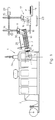
- the device for carrying out the method is connected downstream of a thermoforming machine 1, which heats a film web 2 and deep-draws it with compressed air in a combined molding / punching station 26 and punches out the molded parts 3.
- the table 4 is pivoted with the lower part 5 of the molding / punching tool and the parts 3 are ejected from the lower part 5.
- a turning head 6 takes over the parts 3 and transfers them into the stationary buffer cage 7.
- this stack 8 is formed, several rows of stacks 8 being formed depending on the size of the parts 3 and the molding surface of the upstream thermoforming machine 1.
- a rake 9 is retracted and moved in the stacking direction, so that the stacks 8 come to rest in the stacking cage 10 aligned with the buffering cage 7.
- This stacking cage 10 is pivotally held in a carrier 11 about a horizontally lying axis 12.
- the carrier 11 is connected to rods 13 which are held vertically displaceably in a guide part 14 by means of a drive, not shown.
- the guide part 14 in turn is horizontally displaceable on fixed guides 15 via a drive 29.
- a drive 30, which is arranged on the carrier 11 and which causes the pivoting via a chain drive 16, serves to pivot the stack cage 10.
- the carrier 11 moves with the stack cage 10 horizontally into the stack removal station 17 after the stack transfer.
- the stack cage 10 is pivoted into a horizontal position via the drive 30 and, if necessary, shifted vertically to such an extent that the stacks are ejected 8 can be transferred in rows to the cross conveyor belt 19.
- the other stacks 8 are pushed onto the cross conveyor belt 19 by means of the ejector 18.
- FIG. 3 shows a variant of the method in such a way that the stack cage 10 pivots vertically before the stacks 8 are released and after its horizontal displacement, and the stacks 8 are placed on the cross conveyor belt 19 and then lifted again (position FIG. 3) and withdrawal begins.
- stacks 8 consisting of flat parts such as lids or flat trays can be transported further. In a horizontal position, such stacks 8 would fall apart.
- a pivoting of the stacking cage 10 can, if necessary, take place or not in any desired inclined position, should this be advantageous for various reasons.
- the carrier 11 is additionally proposed to be pivotable about a vertical axis 40, as shown in FIG.
- the carrier 11 is rotatably seated with a pin 37 in the cross member 38 on which the rods 13 are attached.
- a drive 39 e.g. in the form of a pneumatic swivel cylinder or a servo motor, serves to pivot the entire support 11 about the axis 40. In this way, a stacking or pushing out of the stack 8 transversely or in any rotational position, this should for various reasons Further processing of the stack 8 may be advantageous.
- the training according to FIG. 9 is even more universal sit a frame 41 which carries rollers 42, this frame 41 can not with one shown drive on cross members 43 are moved transversely to the stacking direction. In this way, the stack cage 10 can be placed or emptied at any point be as it is cheap.
- Figure 2 shows a possible continuation of the stack 8.
- the cross conveyor belt 19 can alternately by clockwise / anticlockwise rotation a series of stacks 8 on one of the Convey conveyor belts 20, these then bring the stacks 8 onto each Longitudinal conveyor belt 21 in a row, from which a distribution to two more Longitudinal conveyor belts 22 by means of a transfer device 27 is possible to this Way a large number of parts 3 in the total of four Post-processing stations 28, e.g. B. flanging machines, packaging machines, To be able to edit or process this should be necessary.
- Post-processing stations 28 e.g. B. flanging machines, packaging machines, To be able to edit or process this should be necessary.
- a further development of the invention according to FIG. 7 consists in using a plurality of stacking cages 10 and in designing them to be automatically coupled to the carrier 11.
- the carrier 11 leads the stacking cages 10 to a settling station 31.
- the connection is decoupled and each stacking cage 10 is guided horizontally by a displacement device 32 to an unloading station 34, in which the stacks 8 are preferably led out in rows and fed, for example, to a postprocessing station 33.
- the stacking cages 10 are provided with a device which removes the retention of the stack 8 in rows, so that they fall downwards out of the stacking cage 10.
- a displacement device 35 feeds through the row spacing of the stacks 8, so that the next row can be emptied.
- a cooling station 36 can be arranged between the settling station 31 and the unloading station 34, in which the stacks 8 are cooled in a suitable manner, for example by blowing in cooling air, which can be sterile.
- An emptied stacking cage 10 is picked up by the carrier 11 after its horizontal displacement (position in dash-dot lines in FIG. 7) and guided back to the buffer cage 7.
- the stacking cages 10 can be pivoted horizontally in the same way and then set down and shifted horizontally.
- the stacks 8 are then transported in rows by an ejector comparable to the ejector 18 in FIG. 2.
- thermoforming machine 1 qualitatively still poor parts 3 are initially produced (start-up scrap)
- these parts after pivoting the stacking cage 10 into a vertical position, can be ejected or placed onto a separate transverse conveyor belt 23 arranged laterally of the transverse conveyor belt 27, from the device transported out and examined. If good parts come, the device is switched to automatic mode. In this way it is avoided that poor quality parts run into further production and have to be sorted out in a complex manner. A transfer or placement on the cross conveyor belt 19 and removal to the outside is also possible.
- Figure 4 shows the example of a three-row formed / punching die Arrangement of a rake 9 which is perpendicular to the stacking direction via a drive 24 is displaceable and inserted between two cycles of the thermoforming machine 1 becomes. It is also slidable on guides 25 in the stacking direction and passes the Stack 8 from the buffer cage 7 into the stack cage 10 (position with dot-dash lines in FIG. 4).
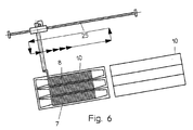
- FIG. 6 Another process sequence of the rake 9 is possible in such a way that the rake 9, starting from the starting position shown in broken lines in FIG. 4, only executes a stroke in the stacking direction, which moves the stack 8 so far that the next parts 3 can be stacked and find a support on the rake 9.
- This position is shown in Figure 6.
- the rake is 9 per cycle Stacking distance shifted in stacking direction. After a few bars if the new center stacked parts 3 each other, the rake 9 moves its Clearing stroke, transfers all stacks 8 into the stacking cage 10 and moves back in Starting position. This sequence of movements is represented by arrows in FIG. 6.
- a servomotive linear drive is preferably used as the drive 29, at which start time and routes, depending on the number of parts 3 per Stack 8 and the stack spacing of parts 3, calculated by the control itself and pretend.
Landscapes
- Engineering & Computer Science (AREA)
- Mechanical Engineering (AREA)
- Stacking Of Articles And Auxiliary Devices (AREA)
- Processing And Handling Of Plastics And Other Materials For Molding In General (AREA)
Abstract
Description
Ein Problem besteht darin, die sich in den Stapelmagazinen bildenden Stapel bei einer bestimmten Länge bzw. Teileanzahl zu leeren und die Stapel weiterzuführen zu einer Nachbearbeitungs- oder Verpackungseinrichtung. Dies insbesondere bei mehrreihiger Auslegung des Form-/Stanzwerkzeuges.
In der DE 198 48 628 A1 wird vorgeschlagen, die zunächst in einer verfahrbaren Fangplatte gestapelten Teile nach Erreichen einer vorgegebenen Anzahl als Stapel in einen verfahrbaren Stapelkorb zu überführen, der dann die Stapel zu einer Entladestation führt und aus dem sie reihenweise auf ein Querförderband geschoben werden. Nachteilig bei diesem Verfahren ist es, dass es zeitaufwendig ist, die Stapel durch Verschiebung der Fangplatte in den verschiebbaren Stapelkorb zu übergeben. Es müssen hierzu bestimmte Hübe zurückgelegt werden, die wegen den Massekräften und den auf die Teile beim Übergeben einwirkenden Kräfte (Deformationsgefahr) mit beschränkter Geschwindigkeit erfolgen müssen. Dieser Problematik muss mit einer genau angepassten Geschwindigkeitsveränderung begegnet werden, die aufwendig ist, ihre Grenzen bei hohen Taktzahlen hat und diese deshalb beschränkt. Die Taktzahl wird aber bei modernen Automaten immer weiter erhöht, wobei das Problem im Stapeln und in der Stapelhandhabung liegt und die Taktzahl begrenzt.
Die bekannte Vorrichtung erlaubt die Überführung der Stapel liegend auf ein horizontal verlaufendes Querförderband. Stapel von relativ flachen Teilen, wie Deckeln und Schalen, neigen in dieser Lage zum Auseinanderdriften und können so nicht weiterbehandelt werden. Solche Stapel müssen stehend transportiert werden, wofür die Vorrichtung nicht geeignet ist. Nachteilig ist auch, dass die Fangplatte in Stapelrichtung beweglich ist und deshalb den Anbau von bestimmten Einrichtungen, die die ersten eingestapelten Teile sicher am Umkippen hindert, erschwert oder unmöglich macht.
Die Vorrichtung zur Durchführung des Verfahrens ist gekennzeichnet durch die Merkmale des Anspruches 12.
- Figur 1
- eine Längsdarstellung der Vorrichtung mit vorgeschalteter Thermoformmaschine
- Figur 2
- eine Draufsicht auf eine Version der Vorrichtung
- Figur 3
- eine Variante der Stapelübergabe.
- Figur 4 bis 6
- einen Pufferkäfig mit einer Stapelentnahmeeinrichtung mit der Funktion einer Gegenhalteeinrichtung
- Figur 7
- eine Weiterbildung der Erfindung mit mehreren wechselbaren Stapelkäfigen.
- Figur 8
- eine Variante der Gestaltung des Trägers für den Stapelkäfig.
- Figur 9
- eine Variante der Verschiebeeinrichtung des Stapelkäfigs.
Gemäß einer ersten Variante des Verfahrens fährt der Träger 11 nach der Stapelübergabe mit dem Stapelkäfig 10 horizontal in die Stapelentnahmestation 17. Dort wird der Stapelkäfig 10 über den Antrieb 30 in horizontale Lage geschwenkt und ggf. soweit vertikal verschoben, dass über einen Ausstoßer 18 die Stapel 8 reihenweise auf das Querförderband 19 übergeben werden können. Nach Absenken des Stapelkäfigs 10 um einen Reihenabstand werden die anderen Stapel 8 mittels des Ausstoßers 18 auf das Querförderband 19 geschoben.
Ein Schwenken des Stapelkäfigs 10 kann bei Bedarf in jede gewünschte Schräglage erfolgen oder unterbleiben, sollte dies aus verschiedenen Gründen vorteilhaft sein.
Die Stapelkäfige 10 sind bei vertikaler Absetzung mit einer Einrichtung versehen, die reihenweise die Rückhaltung der Stapel 8 aufhebt, sodass sie nach unten aus dem Stapelkäfig 10 herausfallen. Eine Verschiebeeinrichtung 35 führt einen Vorschub um den Reihenabstand der Stapel 8 durch, sodass die nächste Reihe entleert werden kann.
Zwischen Absetzstation 31 und Entladestation 34 ist die Anordnung einer Kühlstation 36 möglich, in der in geeigneter Weise eine Kühlung der Stapel 8, z.B. durch Einblassen von Kühlluft, die steril sein kann, erfolgt. Ein geleerter Stapelkäfig 10 wird vom Träger 11 nach dessen horizontaler Verschiebung (Lage strichpunktiert in Figur 7) aufgenommen und zurück zum Pufferkäfig 7 geführt.
Anstelle des in Figur 7 dargestellten vertikalen Absetzens können die Stapelkäfige 10 in gleicher Weise horizontal geschwenkt und dann liegend abgesetzt und verschoben werden. Der reihenweise Austransport der Stapel 8 erfolgt dann durch einen Ausstoßer vergleichbar dem Ausstoßer 18 in Figur 2.
Wenn beim Anfahren der Thermoformmaschine 1 zunächst qualitativ noch schlechte Teile 3 produziert werden (Anfahrausschuss), können diese Teile 3 nach Schwenken des Stapelkäfigs 10 in vertikale Lage vorzugsweise auf ein seitlich des Querförderbandes 27 angeordnetes separates Querförderband 23 ausgeworfen oder auf dieses gesetzt, aus der Vorrichtung heraustransportiert und begutachtet werden. Kommen gute Teile wird die Vorrichtung auf Automatikbetrieb geschaltet. Auf diese Weise wird verhindert, dass qualitativ schlechte Teile in die Weiterproduktion laufen und aufwendig aussortiert werden müssen. Ein Übergeben oder Setzen auf das Querförderband 19 und Austransport nach außen ist ebenfalls möglich.
Claims (18)
- Verfahren zum Stapeln von Teilen (3) aus thermoplastischem Kunststoff, die aus einer erwärmten Folienbahn (2) in einem Form-/Stanzwerkzeug geformt, ausgestanzt, aus diesem direkt oder über eine Übergabeeinrichtung in einen Pufferkäfig (7) übergeben und daraus als Stapel (8) in einen an einem Träger gehaltenen Stapelkäfig (10) überführt, mit diesem zu einer Stapelentnahmestation (17) geführt und dort entnommen werden, dadurch gekennzeichnet, dass der Stapelkäfig (10) vor dem Entnehmen der Stapel (8) wahlweise ansteuerbar um eine horizontale Achse (12) in horizontale, vertikale oder in eine andere, von der Übergabestellung abweichende Lage, geschwenkt wird.
- Verfahren nach Anspruch 1, dadurch gekennzeichnet, dass der Stapelkäfig (10) vor dem Entnehmen der Stapel (8) um eine vertikale Achse (40) verdreht wird.
- Verfahren nach Anspruch 1 oder 2, dadurch gekennzeichnet, dass der Stapelkäfig (10) vor dem Entnehmen der Stapel (8) in Stapelrichtung und/oder quer zur Stapelrichtung verschoben wird.
- Verfahren nach einem der Ansprüche 1 bis 3, dadurch gekennzeichnet, dass vor dem Entnehmen der Stapel (8) aus dem Stapelkäfig (10) der Stapelkäfig (10) vom Träger (11) entkoppelt, von einer Verschiebeeinrichtung (32) in die Stapelentnahmestation (34) transportiert, entleert und wieder mit dem Träger (11) gekoppelt wird.
- Verfahren nach Anspruch 4, dadurch gekennzeichnet, dass die Stapel (8) vor dem Entnehmen aus dem Stapelkäfig (10) in einer Kühlstation (36) gekühlt werden.
- Verfahren nach einem der Ansprüche 1 bis 5, dadurch gekennzeichnet, dass die Stapel (8) beim Entnehmen aus dem Stapelkäfig (10) auf ein Querförderband (19) geführt oder direkt einer Nachbearbeitungseinrichtung (33) zugeführt werden.
- Verfahren nach einem der Ansprüche 1 bis 6, dadurch gekennzeichnet, dass zum Entnehmen von Ausschussteilen der Stapelkäfig (10) in vertikale Lage geschwenkt und die in ihm befindlichen Teile (3) bzw. Stapel (8) ausgeworfen werden.
- Verfahren nach Anspruch 7, dadurch gekennzeichnet, dass die Ausschussteile auf ein Querförderband (23) geworfen oder gesetzt werden.
- Verfahren nach einem der Ansprüche 1 bis 8, dadurch gekennzeichnet, dass der Rechen (9) zum Überführen der Stapel (8) vom Pufferkäfig (7) in den Stapelkäfig (10) zeitweise als Stützeinrichtung für die in den Pufferkäfig (7) übergebenen Teile (3) verwendet wird.
- Verfahren nach Anspruch 9, dadurch gekennzeichnet, dass der Rechen (9) zunächst alle Stapel (8) aus dem Pufferkäfig (7) in den Stapelkäfig (10) überführt und dann in eingefahrenem Zustand zurück in den Pufferkäfig (7) vor die vordersten Teile (3) geführt und mehrere Takte jeweils um den Stapelabstand zwischen zwei Teilen (3) in Stapelrichtung verschoben wird.
- Verfahren nach Anspruch 9, dadurch gekennzeichnet, dass der Rechen (9) nach dem seitlichen Einfahren hinter die im Pufferkäfig (7) befindlichen Stapel (8) zunächst einen Hub ausführt, der der Höhe der Teile (3) entspricht, dann mehrere Takte jeweils einen Hub entsprechend dem Stapelabstand der Teile (3) ausführt und dann das Überführen der Stapel (8) in den Stapelkäfig (10) durchführt.
- Vorrichtung zum Stapeln von Teilen (3) aus thermoplastischem Kunststoff zum Nachschalten an eine Thermoformmaschine, mit einem Pufferkäfig (7), einem in Stapelrichtung nachfolgend angeordneten, an einem Träger (11) gehaltenen Stapelkäfig (10) und mit einer Einrichtung zum Überführen der Stapel (8) vom Pufferkäfig (7) in den Stapelkäfig (10), dadurch gekennzeichnet, dass der Stapelkäfig (10) schwenkbar um eine horizontale Achse (12) im Träger (11) gehalten ist und mit einem Antrieb (30) in Wirkverbindung steht, der jede beliebige Schwenklage des Stapelkäfigs (10) um die Achse (12) anfahren kann.
- Vorrichtung nach Anspruch 12, dadurch gekennzeichnet, dass der Träger (11) drehbar um eine vertikale Achse (40) ausgebildet ist.
- Vorrichtung nach Anspruch 12 oder 13, dadurch gekennzeichnet, dass der Träger (11) in Stapelrichtung und/oder quer zur Stapelrichtung verschiebbar ausgebildet ist.
- Vorrichtung nach einem der Ansprüche 12 bis 14, gekennzeichnet durch eine automatisch betätigbare Kopplungseinrichtung zwischen Träger (11) und Stapelkäfig (10) und eine Verschiebeeinrichtung (32) zum Weitertransport der entkoppelten Stapelkäfige (10) von einer Absetzstation (31) in die Stapelentnahmestation (34).
- Vorrichtung nach Anspruch 15, gekennzeichnet durch eine zwischen Absetzstation (31) und Stapelentnahmestation (43) angeordnete Kühlstation (36).
- Vorrichtung nach einem der Ansprüche 12 bis 16, dadurch gekennzeichnet, dass die Einrichtung zum Überführen der Stapel (8) vom Pufferkäfig (7) in den Stapelkäfig (10) von einem Servomotor (29) angetrieben wird.
- Vorrichtung nach einem der Ansprüche 12 bis 17, dadurch gekennzeichnet, dass die Einrichtung zum Überführen der Stapel (8) vom Pufferkäfig (7) in den Stapelkäfig (10) von einem quer zur Stapelrichtung verschiebbaren Rechen (9) gebildet wird.
Applications Claiming Priority (2)
| Application Number | Priority Date | Filing Date | Title |
|---|---|---|---|
| DE10052759A DE10052759C2 (de) | 2000-10-25 | 2000-10-25 | Vorrichtung zum Stapeln von Teilen aus thermoplastischem Kunststoff |
| DE10052759 | 2000-10-25 |
Publications (2)
| Publication Number | Publication Date |
|---|---|
| EP1201574A1 true EP1201574A1 (de) | 2002-05-02 |
| EP1201574B1 EP1201574B1 (de) | 2004-09-15 |
Family
ID=7660930
Family Applications (1)
| Application Number | Title | Priority Date | Filing Date |
|---|---|---|---|
| EP01124822A Expired - Lifetime EP1201574B1 (de) | 2000-10-25 | 2001-10-18 | Verfahren zum Stapeln von Teilen aus thermoplastischem Kunststoff und Vorrichtung zur Durchführung des Verfahrens |
Country Status (4)
| Country | Link |
|---|---|
| EP (1) | EP1201574B1 (de) |
| AT (1) | ATE276184T1 (de) |
| DE (2) | DE10052759C2 (de) |
| DK (1) | DK1201574T3 (de) |
Cited By (4)
| Publication number | Priority date | Publication date | Assignee | Title |
|---|---|---|---|---|
| WO2004050329A1 (en) * | 2002-12-04 | 2004-06-17 | Amut S.P.A. | A machine for stacking articles |
| US6851920B2 (en) | 2000-10-25 | 2005-02-08 | Adolf Illig Maschinenbau Gmbh & Co. | Method for stacking parts comprising thermoplastic plastic, and apparatus for executing the method |
| EP1731453A1 (de) * | 2005-06-09 | 2006-12-13 | Kiefel Ag | Verfahren und Vorrichtung zum Stapeln von tiefgezogenen Artikeln |
| ITBO20090800A1 (it) * | 2009-12-15 | 2011-06-16 | Sts Internat S R L | Dispositivo per il raffreddamento di una fila di bicchieri in plastica inseriti parzialmente l'uno dentro l'altro e movimentati lungo una linea di alimentazione |
Families Citing this family (4)
| Publication number | Priority date | Publication date | Assignee | Title |
|---|---|---|---|---|
| DE10256141A1 (de) * | 2002-06-21 | 2004-02-05 | Walter Lauermann | Formlings-Stapelsystem mit Gegenhalt |
| DE10356001B4 (de) * | 2002-11-28 | 2006-08-17 | Walter Lauermann | Stapel-Übergabeverfahren, -anordnung und -vorrichtung |
| DE102004011002A1 (de) * | 2004-03-06 | 2005-09-22 | Gabler Thermoform Gmbh & Co. Kg | Verfahren zum Betreiben einer Thermoformmaschine und Thermoformmaschine |
| DE102012202756B4 (de) * | 2012-02-23 | 2016-02-11 | Marbach Werkzeugbau Gmbh | Vorrichtung zur Handhabung von Formteilen aus thermoplastischem Kunststoff |
Citations (8)
| Publication number | Priority date | Publication date | Assignee | Title |
|---|---|---|---|---|
| US3491633A (en) * | 1967-02-01 | 1970-01-27 | Brown Machine Co Of Michigan | Plastic container transfer apparatus and methods |
| DE7330214U (de) * | 1973-08-18 | 1975-02-20 | Illig A Maschinenbau | Thermoformautomat |
| DE3346628C2 (de) | 1983-12-23 | 1986-03-27 | Adolf Illig Maschinenbau Gmbh & Co, 7100 Heilbronn | Vorrichtung zum Formen, Stanzen und Stapeln von tiefgezogenen Teilen aus thermoplastischem Kunststoff |
| DE19742107A1 (de) * | 1997-09-24 | 1999-03-25 | Illig Maschinenbau Adolf | Vorrichtung zum Formen, Stanzen und Stapeln von Behältern aus einer Folienbahn aus thermoplastischem Kunststoff |
| DE19812414A1 (de) | 1998-03-20 | 1999-09-23 | Walter Lauermann | Aufnahmeverfahren und -vorrichtung für Serien-Erzeugnisse, insbesondere Kunststoff-Becher |
| EP0955150A2 (de) * | 1998-02-11 | 1999-11-10 | Gabler Maschinenbau GmbH | Stapelvorrichtung für eine Thermoformmaschine |
| DE19848628A1 (de) | 1998-10-22 | 2000-04-27 | Gabler Gmbh Maschbau | Thermoformmaschine |
| DE19852359C1 (de) | 1998-11-13 | 2000-08-31 | Illig Maschinenbau Adolf | Vorrichtung zum Aufnehmen und Stapeln von Behältern aus thermoplastischem Kunststoff |
Family Cites Families (2)
| Publication number | Priority date | Publication date | Assignee | Title |
|---|---|---|---|---|
| DE7129534U (de) * | 1971-11-18 | Illig A Maschinenbau | Vorrichtung zum Stapeln und Zahlen von Gegenstanden aus thermoplastischer Kunst stoffohe | |
| DE4436531C1 (de) * | 1994-10-13 | 1996-04-04 | Illig Maschinenbau Adolf | Verfahren zum Überführen von mehrreihig aus einer thermoplastischen Kunstoffolie geformten und ausgestanzten Artikeln in einreihige Stapel und Vorrichtung zur Durchführung des Verfahrens |
-
2000
- 2000-10-25 DE DE10052759A patent/DE10052759C2/de not_active Expired - Fee Related
-
2001
- 2001-10-18 DK DK01124822T patent/DK1201574T3/da active
- 2001-10-18 AT AT01124822T patent/ATE276184T1/de active
- 2001-10-18 DE DE50103608T patent/DE50103608D1/de not_active Expired - Lifetime
- 2001-10-18 EP EP01124822A patent/EP1201574B1/de not_active Expired - Lifetime
Patent Citations (8)
| Publication number | Priority date | Publication date | Assignee | Title |
|---|---|---|---|---|
| US3491633A (en) * | 1967-02-01 | 1970-01-27 | Brown Machine Co Of Michigan | Plastic container transfer apparatus and methods |
| DE7330214U (de) * | 1973-08-18 | 1975-02-20 | Illig A Maschinenbau | Thermoformautomat |
| DE3346628C2 (de) | 1983-12-23 | 1986-03-27 | Adolf Illig Maschinenbau Gmbh & Co, 7100 Heilbronn | Vorrichtung zum Formen, Stanzen und Stapeln von tiefgezogenen Teilen aus thermoplastischem Kunststoff |
| DE19742107A1 (de) * | 1997-09-24 | 1999-03-25 | Illig Maschinenbau Adolf | Vorrichtung zum Formen, Stanzen und Stapeln von Behältern aus einer Folienbahn aus thermoplastischem Kunststoff |
| EP0955150A2 (de) * | 1998-02-11 | 1999-11-10 | Gabler Maschinenbau GmbH | Stapelvorrichtung für eine Thermoformmaschine |
| DE19812414A1 (de) | 1998-03-20 | 1999-09-23 | Walter Lauermann | Aufnahmeverfahren und -vorrichtung für Serien-Erzeugnisse, insbesondere Kunststoff-Becher |
| DE19848628A1 (de) | 1998-10-22 | 2000-04-27 | Gabler Gmbh Maschbau | Thermoformmaschine |
| DE19852359C1 (de) | 1998-11-13 | 2000-08-31 | Illig Maschinenbau Adolf | Vorrichtung zum Aufnehmen und Stapeln von Behältern aus thermoplastischem Kunststoff |
Cited By (6)
| Publication number | Priority date | Publication date | Assignee | Title |
|---|---|---|---|---|
| US6851920B2 (en) | 2000-10-25 | 2005-02-08 | Adolf Illig Maschinenbau Gmbh & Co. | Method for stacking parts comprising thermoplastic plastic, and apparatus for executing the method |
| WO2004050329A1 (en) * | 2002-12-04 | 2004-06-17 | Amut S.P.A. | A machine for stacking articles |
| EP1731453A1 (de) * | 2005-06-09 | 2006-12-13 | Kiefel Ag | Verfahren und Vorrichtung zum Stapeln von tiefgezogenen Artikeln |
| US7690883B2 (en) | 2005-06-09 | 2010-04-06 | Kiefel Gmbh | Pivoting basket stacker for deep-drawn articles |
| DE102005026687B4 (de) * | 2005-06-09 | 2017-05-24 | Kiefel Gmbh | Verfahren und Vorrichtung zum Stapeln von tiefgezogenen Artikeln |
| ITBO20090800A1 (it) * | 2009-12-15 | 2011-06-16 | Sts Internat S R L | Dispositivo per il raffreddamento di una fila di bicchieri in plastica inseriti parzialmente l'uno dentro l'altro e movimentati lungo una linea di alimentazione |
Also Published As
| Publication number | Publication date |
|---|---|
| DE50103608D1 (de) | 2004-10-21 |
| EP1201574B1 (de) | 2004-09-15 |
| ATE276184T1 (de) | 2004-10-15 |
| DE10052759C2 (de) | 2002-11-07 |
| DK1201574T3 (da) | 2005-01-24 |
| DE10052759A1 (de) | 2002-05-16 |
Similar Documents
| Publication | Publication Date | Title |
|---|---|---|
| DE4244977C2 (de) | Thermoformmaschine und Verfahren zum Herstellen von hohlen Gegenständen | |
| EP3106241B1 (de) | Werkzeugmaschine und verfahren zum ausschleusen von werkstückteilen | |
| DE2953681C2 (de) | Schneidmaschine | |
| DE102007049168B4 (de) | Vorrichtung und Verfahren zum Verschieben von aus erwärmten thermoplastischen Halbzeugen geformten und ausgestanzten Tiefziehprodukten von einer Thermoformmaschine zu einer Verarbeitungsstation | |
| DE19933355C1 (de) | Verfahren zum Stapeln von Behältern aus thermoplastischem Kunststoff und Vorrichtung zur Durchführung des Verfahrens | |
| DE69702572T2 (de) | Vorrichtung zum Entformen und Nachbehandeln von in einer Thermoformmaschine warmgeformten Gegenständen | |
| DE2141672A1 (de) | Vorrichtung für die Entformung und die Handhabung von Hohlkörpern aus Kunststoffmaterial | |
| DE60314850T2 (de) | Vorformlingbeförderungsvorrichtung | |
| EP2495193B1 (de) | Vorrichtung zum Ausschleusen von Behältern | |
| EP3167709B1 (de) | Verfahren und vorrichtung zur handhabung von käselaiben | |
| DE69606637T2 (de) | Verfahren und vorrichtung zum automatischen stapeln bon beuteln und ablegender stapel auf eine spindel | |
| EP1000887B1 (de) | Vorrichtung zum Aufnehmen und Stapeln von Behältern aus thermoplastischem Kunststoff | |
| WO2005075293A1 (de) | Verfahren und vorrichtung zum überführen von produkten aus einem vorratsgefäss in die näpfe einer folie | |
| DE10052759C2 (de) | Vorrichtung zum Stapeln von Teilen aus thermoplastischem Kunststoff | |
| EP1731453B1 (de) | Verfahren und Vorrichtung zum Stapeln von tiefgezogenen Artikeln | |
| EP1195337B1 (de) | Verfahren zum Stapeln von Behältern aus thermoplastischem Kunststoff und Vorrichtung zur Durchführung des Verfahrens | |
| DE68914311T2 (de) | Verfahren zum automatischen Herstellen von einem mit einem Etikett bekleideten Behälter, insbesondere Behälter mit rundem Querschnitt, und Vorrichtung zur Durchführung dieses Verfahrens. | |
| DE4436531C1 (de) | Verfahren zum Überführen von mehrreihig aus einer thermoplastischen Kunstoffolie geformten und ausgestanzten Artikeln in einreihige Stapel und Vorrichtung zur Durchführung des Verfahrens | |
| DE10007333C2 (de) | Vorrichtung zum Stapeln von Behältern aus thermoplastischem Kunststoff | |
| DE3822363C2 (de) | ||
| DE3337243A1 (de) | Einrichtung zur fertigung gepresster gegenstaende | |
| DE102004050917A1 (de) | Vorrichtung zum Stapeln von Formteilen aus thermoplastischem Kunststoff | |
| DE69615150T2 (de) | Verfahren und vorrichtung zum laden von etiketten in eine form einer warmformmaschine | |
| EP1570972B1 (de) | Thermoformmaschine mit Zwischenspeicher und Verfahren zum Betreiben selbiger | |
| EP1075923A1 (de) | Verfahren zum Stapeln von Behältern aus thermoplastischem Kunststoff und Vorrichtung zur Durchführung des Verfahrens |
Legal Events
| Date | Code | Title | Description |
|---|---|---|---|
| PUAI | Public reference made under article 153(3) epc to a published international application that has entered the european phase |
Free format text: ORIGINAL CODE: 0009012 |
|
| AK | Designated contracting states |
Kind code of ref document: A1 Designated state(s): AT BE CH CY DE DK ES FI FR GB GR IE IT LI LU MC NL PT SE TR |
|
| AX | Request for extension of the european patent |
Free format text: AL;LT;LV;MK;RO;SI |
|
| 17P | Request for examination filed |
Effective date: 20020311 |
|
| RAP1 | Party data changed (applicant data changed or rights of an application transferred) |
Owner name: ADOLF ILLIG MASCHINENBAU GMBH & CO. KG |
|
| AKX | Designation fees paid |
Free format text: AT BE CH CY DE DK ES FI FR GB GR IE IT LI LU MC NL PT SE TR |
|
| 17Q | First examination report despatched |
Effective date: 20030707 |
|
| GRAP | Despatch of communication of intention to grant a patent |
Free format text: ORIGINAL CODE: EPIDOSNIGR1 |
|
| GRAS | Grant fee paid |
Free format text: ORIGINAL CODE: EPIDOSNIGR3 |
|
| GRAA | (expected) grant |
Free format text: ORIGINAL CODE: 0009210 |
|
| AK | Designated contracting states |
Kind code of ref document: B1 Designated state(s): AT BE CH CY DE DK ES FI FR GB GR IE IT LI LU MC NL PT SE TR |
|
| PG25 | Lapsed in a contracting state [announced via postgrant information from national office to epo] |
Ref country code: CY Free format text: LAPSE BECAUSE OF FAILURE TO SUBMIT A TRANSLATION OF THE DESCRIPTION OR TO PAY THE FEE WITHIN THE PRESCRIBED TIME-LIMIT Effective date: 20040915 Ref country code: NL Free format text: LAPSE BECAUSE OF FAILURE TO SUBMIT A TRANSLATION OF THE DESCRIPTION OR TO PAY THE FEE WITHIN THE PRESCRIBED TIME-LIMIT Effective date: 20040915 Ref country code: TR Free format text: LAPSE BECAUSE OF FAILURE TO SUBMIT A TRANSLATION OF THE DESCRIPTION OR TO PAY THE FEE WITHIN THE PRESCRIBED TIME-LIMIT Effective date: 20040915 Ref country code: FR Free format text: LAPSE BECAUSE OF FAILURE TO SUBMIT A TRANSLATION OF THE DESCRIPTION OR TO PAY THE FEE WITHIN THE PRESCRIBED TIME-LIMIT Effective date: 20040915 Ref country code: IE Free format text: LAPSE BECAUSE OF FAILURE TO SUBMIT A TRANSLATION OF THE DESCRIPTION OR TO PAY THE FEE WITHIN THE PRESCRIBED TIME-LIMIT Effective date: 20040915 Ref country code: FI Free format text: LAPSE BECAUSE OF FAILURE TO SUBMIT A TRANSLATION OF THE DESCRIPTION OR TO PAY THE FEE WITHIN THE PRESCRIBED TIME-LIMIT Effective date: 20040915 |
|
| REG | Reference to a national code |
Ref country code: GB Ref legal event code: FG4D Free format text: NOT ENGLISH Ref country code: CH Ref legal event code: EP |
|
| PG25 | Lapsed in a contracting state [announced via postgrant information from national office to epo] |
Ref country code: LU Free format text: LAPSE BECAUSE OF NON-PAYMENT OF DUE FEES Effective date: 20041018 |
|
| REG | Reference to a national code |
Ref country code: IE Ref legal event code: FG4D Free format text: GERMAN |
|
| REF | Corresponds to: |
Ref document number: 50103608 Country of ref document: DE Date of ref document: 20041021 Kind code of ref document: P |
|
| PG25 | Lapsed in a contracting state [announced via postgrant information from national office to epo] |
Ref country code: BE Free format text: LAPSE BECAUSE OF NON-PAYMENT OF DUE FEES Effective date: 20041031 Ref country code: MC Free format text: LAPSE BECAUSE OF NON-PAYMENT OF DUE FEES Effective date: 20041031 |
|
| RAP2 | Party data changed (patent owner data changed or rights of a patent transferred) |
Owner name: ADOLF ILLIG MASCHINENBAU GMBH & CO. KG |
|
| PG25 | Lapsed in a contracting state [announced via postgrant information from national office to epo] |
Ref country code: GR Free format text: LAPSE BECAUSE OF FAILURE TO SUBMIT A TRANSLATION OF THE DESCRIPTION OR TO PAY THE FEE WITHIN THE PRESCRIBED TIME-LIMIT Effective date: 20041215 Ref country code: SE Free format text: LAPSE BECAUSE OF FAILURE TO SUBMIT A TRANSLATION OF THE DESCRIPTION OR TO PAY THE FEE WITHIN THE PRESCRIBED TIME-LIMIT Effective date: 20041215 |
|
| PG25 | Lapsed in a contracting state [announced via postgrant information from national office to epo] |
Ref country code: ES Free format text: LAPSE BECAUSE OF FAILURE TO SUBMIT A TRANSLATION OF THE DESCRIPTION OR TO PAY THE FEE WITHIN THE PRESCRIBED TIME-LIMIT Effective date: 20041226 |
|
| NLT2 | Nl: modifications (of names), taken from the european patent patent bulletin |
Owner name: ADOLF ILLIG MASCHINENBAU GMBH & CO. KG |
|
| REG | Reference to a national code |
Ref country code: DK Ref legal event code: T3 |
|
| GBT | Gb: translation of ep patent filed (gb section 77(6)(a)/1977) |
Effective date: 20050115 |
|
| NLV1 | Nl: lapsed or annulled due to failure to fulfill the requirements of art. 29p and 29m of the patents act | ||
| REG | Reference to a national code |
Ref country code: IE Ref legal event code: FD4D |
|
| BERE | Be: lapsed |
Owner name: ADOLF ILLIG MASCHINENBAU G.M.B.H. & CO. KG Effective date: 20041031 |
|
| PLBE | No opposition filed within time limit |
Free format text: ORIGINAL CODE: 0009261 |
|
| STAA | Information on the status of an ep patent application or granted ep patent |
Free format text: STATUS: NO OPPOSITION FILED WITHIN TIME LIMIT |
|
| 26N | No opposition filed |
Effective date: 20050616 |
|
| EN | Fr: translation not filed | ||
| PG25 | Lapsed in a contracting state [announced via postgrant information from national office to epo] |
Ref country code: LI Free format text: LAPSE BECAUSE OF NON-PAYMENT OF DUE FEES Effective date: 20051031 Ref country code: CH Free format text: LAPSE BECAUSE OF NON-PAYMENT OF DUE FEES Effective date: 20051031 |
|
| REG | Reference to a national code |
Ref country code: CH Ref legal event code: PL |
|
| BERE | Be: lapsed |
Owner name: ADOLF *ILLIG MASCHINENBAU G.M.B.H. & CO. K.G. Effective date: 20041031 |
|
| PG25 | Lapsed in a contracting state [announced via postgrant information from national office to epo] |
Ref country code: PT Free format text: LAPSE BECAUSE OF NON-PAYMENT OF DUE FEES Effective date: 20050215 |
|
| PGFP | Annual fee paid to national office [announced via postgrant information from national office to epo] |
Ref country code: DK Payment date: 20141027 Year of fee payment: 14 |
|
| PGFP | Annual fee paid to national office [announced via postgrant information from national office to epo] |
Ref country code: GB Payment date: 20141024 Year of fee payment: 14 |
|
| PGFP | Annual fee paid to national office [announced via postgrant information from national office to epo] |
Ref country code: AT Payment date: 20141022 Year of fee payment: 14 |
|
| PGFP | Annual fee paid to national office [announced via postgrant information from national office to epo] |
Ref country code: IT Payment date: 20141023 Year of fee payment: 14 |
|
| REG | Reference to a national code |
Ref country code: DK Ref legal event code: EBP Effective date: 20151031 |
|
| REG | Reference to a national code |
Ref country code: AT Ref legal event code: MM01 Ref document number: 276184 Country of ref document: AT Kind code of ref document: T Effective date: 20151018 |
|
| GBPC | Gb: european patent ceased through non-payment of renewal fee |
Effective date: 20151018 |
|
| PG25 | Lapsed in a contracting state [announced via postgrant information from national office to epo] |
Ref country code: GB Free format text: LAPSE BECAUSE OF NON-PAYMENT OF DUE FEES Effective date: 20151018 Ref country code: IT Free format text: LAPSE BECAUSE OF NON-PAYMENT OF DUE FEES Effective date: 20151018 |
|
| PG25 | Lapsed in a contracting state [announced via postgrant information from national office to epo] |
Ref country code: AT Free format text: LAPSE BECAUSE OF NON-PAYMENT OF DUE FEES Effective date: 20151018 |
|
| PG25 | Lapsed in a contracting state [announced via postgrant information from national office to epo] |
Ref country code: DK Free format text: LAPSE BECAUSE OF NON-PAYMENT OF DUE FEES Effective date: 20151031 |
|
| PGFP | Annual fee paid to national office [announced via postgrant information from national office to epo] |
Ref country code: DE Payment date: 20201001 Year of fee payment: 20 |
|
| REG | Reference to a national code |
Ref country code: DE Ref legal event code: R071 Ref document number: 50103608 Country of ref document: DE |