EP1201264A1 - Disposablekassette mit Dichtungsmembran sowie Ventilaktor hierfür - Google Patents
Disposablekassette mit Dichtungsmembran sowie Ventilaktor hierfür Download PDFInfo
- Publication number
- EP1201264A1 EP1201264A1 EP20010125165 EP01125165A EP1201264A1 EP 1201264 A1 EP1201264 A1 EP 1201264A1 EP 20010125165 EP20010125165 EP 20010125165 EP 01125165 A EP01125165 A EP 01125165A EP 1201264 A1 EP1201264 A1 EP 1201264A1
- Authority
- EP
- European Patent Office
- Prior art keywords
- channel
- main
- main channel
- flow
- mouth
- Prior art date
- Legal status (The legal status is an assumption and is not a legal conclusion. Google has not performed a legal analysis and makes no representation as to the accuracy of the status listed.)
- Granted
Links
- 239000012528 membrane Substances 0.000 title claims description 10
- 238000007789 sealing Methods 0.000 title description 6
- 239000013039 cover film Substances 0.000 claims abstract description 39
- 239000007788 liquid Substances 0.000 claims abstract description 13
- 239000012530 fluid Substances 0.000 claims description 47
- 210000004369 blood Anatomy 0.000 claims description 15
- 239000008280 blood Substances 0.000 claims description 15
- 238000003825 pressing Methods 0.000 claims description 6
- 229920001971 elastomer Polymers 0.000 claims description 4
- 239000000806 elastomer Substances 0.000 claims description 4
- 238000011144 upstream manufacturing Methods 0.000 claims description 2
- 238000000502 dialysis Methods 0.000 claims 1
- 239000010408 film Substances 0.000 abstract description 5
- 239000003814 drug Substances 0.000 abstract description 2
- 238000011161 development Methods 0.000 description 4
- 238000005070 sampling Methods 0.000 description 3
- 230000015572 biosynthetic process Effects 0.000 description 2
- 230000017531 blood circulation Effects 0.000 description 2
- 238000013461 design Methods 0.000 description 2
- 238000005516 engineering process Methods 0.000 description 2
- 230000002349 favourable effect Effects 0.000 description 2
- 239000011888 foil Substances 0.000 description 2
- 238000005755 formation reaction Methods 0.000 description 2
- 238000001631 haemodialysis Methods 0.000 description 2
- 230000000322 hemodialysis Effects 0.000 description 2
- 238000001746 injection moulding Methods 0.000 description 2
- HTTJABKRGRZYRN-UHFFFAOYSA-N Heparin Chemical compound OC1C(NC(=O)C)C(O)OC(COS(O)(=O)=O)C1OC1C(OS(O)(=O)=O)C(O)C(OC2C(C(OS(O)(=O)=O)C(OC3C(C(O)C(O)C(O3)C(O)=O)OS(O)(=O)=O)C(CO)O2)NS(O)(=O)=O)C(C(O)=O)O1 HTTJABKRGRZYRN-UHFFFAOYSA-N 0.000 description 1
- 230000001154 acute effect Effects 0.000 description 1
- 210000000601 blood cell Anatomy 0.000 description 1
- 238000011109 contamination Methods 0.000 description 1
- 230000006735 deficit Effects 0.000 description 1
- 230000001419 dependent effect Effects 0.000 description 1
- 239000000385 dialysis solution Substances 0.000 description 1
- 229940079593 drug Drugs 0.000 description 1
- 238000002615 hemofiltration Methods 0.000 description 1
- 229960002897 heparin Drugs 0.000 description 1
- 229920000669 heparin Polymers 0.000 description 1
- 239000003978 infusion fluid Substances 0.000 description 1
- 239000007924 injection Substances 0.000 description 1
- 238000002347 injection Methods 0.000 description 1
- 238000003780 insertion Methods 0.000 description 1
- 230000037431 insertion Effects 0.000 description 1
- 238000009434 installation Methods 0.000 description 1
- 238000004519 manufacturing process Methods 0.000 description 1
- 238000010327 methods by industry Methods 0.000 description 1
- 238000005086 pumping Methods 0.000 description 1
- 238000000926 separation method Methods 0.000 description 1
- 238000001179 sorption measurement Methods 0.000 description 1
- 230000003068 static effect Effects 0.000 description 1
- 239000002344 surface layer Substances 0.000 description 1
- 238000003466 welding Methods 0.000 description 1
- 230000037303 wrinkles Effects 0.000 description 1
Images

Classifications
-
- A—HUMAN NECESSITIES
- A61—MEDICAL OR VETERINARY SCIENCE; HYGIENE
- A61M—DEVICES FOR INTRODUCING MEDIA INTO, OR ONTO, THE BODY; DEVICES FOR TRANSDUCING BODY MEDIA OR FOR TAKING MEDIA FROM THE BODY; DEVICES FOR PRODUCING OR ENDING SLEEP OR STUPOR
- A61M39/00—Tubes, tube connectors, tube couplings, valves, access sites or the like, specially adapted for medical use
- A61M39/22—Valves or arrangement of valves
-
- A—HUMAN NECESSITIES
- A61—MEDICAL OR VETERINARY SCIENCE; HYGIENE
- A61M—DEVICES FOR INTRODUCING MEDIA INTO, OR ONTO, THE BODY; DEVICES FOR TRANSDUCING BODY MEDIA OR FOR TAKING MEDIA FROM THE BODY; DEVICES FOR PRODUCING OR ENDING SLEEP OR STUPOR
- A61M1/00—Suction or pumping devices for medical purposes; Devices for carrying-off, for treatment of, or for carrying-over, body-liquids; Drainage systems
- A61M1/36—Other treatment of blood in a by-pass of the natural circulatory system, e.g. temperature adaptation, irradiation ; Extra-corporeal blood circuits
- A61M1/3621—Extra-corporeal blood circuits
- A61M1/3622—Extra-corporeal blood circuits with a cassette forming partially or totally the blood circuit
- A61M1/36222—Details related to the interface between cassette and machine
- A61M1/362223—Details related to the interface between cassette and machine the interface being evacuated interfaces to enhance contact
-
- A—HUMAN NECESSITIES
- A61—MEDICAL OR VETERINARY SCIENCE; HYGIENE
- A61M—DEVICES FOR INTRODUCING MEDIA INTO, OR ONTO, THE BODY; DEVICES FOR TRANSDUCING BODY MEDIA OR FOR TAKING MEDIA FROM THE BODY; DEVICES FOR PRODUCING OR ENDING SLEEP OR STUPOR
- A61M1/00—Suction or pumping devices for medical purposes; Devices for carrying-off, for treatment of, or for carrying-over, body-liquids; Drainage systems
- A61M1/36—Other treatment of blood in a by-pass of the natural circulatory system, e.g. temperature adaptation, irradiation ; Extra-corporeal blood circuits
- A61M1/3621—Extra-corporeal blood circuits
- A61M1/3622—Extra-corporeal blood circuits with a cassette forming partially or totally the blood circuit
- A61M1/36226—Constructional details of cassettes, e.g. specific details on material or shape
- A61M1/362265—Details of valves
-
- A—HUMAN NECESSITIES
- A61—MEDICAL OR VETERINARY SCIENCE; HYGIENE
- A61M—DEVICES FOR INTRODUCING MEDIA INTO, OR ONTO, THE BODY; DEVICES FOR TRANSDUCING BODY MEDIA OR FOR TAKING MEDIA FROM THE BODY; DEVICES FOR PRODUCING OR ENDING SLEEP OR STUPOR
- A61M1/00—Suction or pumping devices for medical purposes; Devices for carrying-off, for treatment of, or for carrying-over, body-liquids; Drainage systems
- A61M1/36—Other treatment of blood in a by-pass of the natural circulatory system, e.g. temperature adaptation, irradiation ; Extra-corporeal blood circuits
- A61M1/3621—Extra-corporeal blood circuits
- A61M1/367—Circuit parts not covered by the preceding subgroups of group A61M1/3621
-
- A—HUMAN NECESSITIES
- A61—MEDICAL OR VETERINARY SCIENCE; HYGIENE
- A61M—DEVICES FOR INTRODUCING MEDIA INTO, OR ONTO, THE BODY; DEVICES FOR TRANSDUCING BODY MEDIA OR FOR TAKING MEDIA FROM THE BODY; DEVICES FOR PRODUCING OR ENDING SLEEP OR STUPOR
- A61M1/00—Suction or pumping devices for medical purposes; Devices for carrying-off, for treatment of, or for carrying-over, body-liquids; Drainage systems
- A61M1/36—Other treatment of blood in a by-pass of the natural circulatory system, e.g. temperature adaptation, irradiation ; Extra-corporeal blood circuits
- A61M1/3621—Extra-corporeal blood circuits
- A61M1/3622—Extra-corporeal blood circuits with a cassette forming partially or totally the blood circuit
-
- A—HUMAN NECESSITIES
- A61—MEDICAL OR VETERINARY SCIENCE; HYGIENE
- A61M—DEVICES FOR INTRODUCING MEDIA INTO, OR ONTO, THE BODY; DEVICES FOR TRANSDUCING BODY MEDIA OR FOR TAKING MEDIA FROM THE BODY; DEVICES FOR PRODUCING OR ENDING SLEEP OR STUPOR
- A61M1/00—Suction or pumping devices for medical purposes; Devices for carrying-off, for treatment of, or for carrying-over, body-liquids; Drainage systems
- A61M1/36—Other treatment of blood in a by-pass of the natural circulatory system, e.g. temperature adaptation, irradiation ; Extra-corporeal blood circuits
- A61M1/3621—Extra-corporeal blood circuits
- A61M1/3622—Extra-corporeal blood circuits with a cassette forming partially or totally the blood circuit
- A61M1/36226—Constructional details of cassettes, e.g. specific details on material or shape
-
- A—HUMAN NECESSITIES
- A61—MEDICAL OR VETERINARY SCIENCE; HYGIENE
- A61M—DEVICES FOR INTRODUCING MEDIA INTO, OR ONTO, THE BODY; DEVICES FOR TRANSDUCING BODY MEDIA OR FOR TAKING MEDIA FROM THE BODY; DEVICES FOR PRODUCING OR ENDING SLEEP OR STUPOR
- A61M2205/00—General characteristics of the apparatus
- A61M2205/12—General characteristics of the apparatus with interchangeable cassettes forming partially or totally the fluid circuit
- A61M2205/121—General characteristics of the apparatus with interchangeable cassettes forming partially or totally the fluid circuit interface between cassette and base
- A61M2205/122—General characteristics of the apparatus with interchangeable cassettes forming partially or totally the fluid circuit interface between cassette and base using evacuated interfaces to enhance contact
-
- A—HUMAN NECESSITIES
- A61—MEDICAL OR VETERINARY SCIENCE; HYGIENE
- A61M—DEVICES FOR INTRODUCING MEDIA INTO, OR ONTO, THE BODY; DEVICES FOR TRANSDUCING BODY MEDIA OR FOR TAKING MEDIA FROM THE BODY; DEVICES FOR PRODUCING OR ENDING SLEEP OR STUPOR
- A61M2205/00—General characteristics of the apparatus
- A61M2205/12—General characteristics of the apparatus with interchangeable cassettes forming partially or totally the fluid circuit
- A61M2205/128—General characteristics of the apparatus with interchangeable cassettes forming partially or totally the fluid circuit with incorporated valves
-
- Y—GENERAL TAGGING OF NEW TECHNOLOGICAL DEVELOPMENTS; GENERAL TAGGING OF CROSS-SECTIONAL TECHNOLOGIES SPANNING OVER SEVERAL SECTIONS OF THE IPC; TECHNICAL SUBJECTS COVERED BY FORMER USPC CROSS-REFERENCE ART COLLECTIONS [XRACs] AND DIGESTS
- Y10—TECHNICAL SUBJECTS COVERED BY FORMER USPC
- Y10T—TECHNICAL SUBJECTS COVERED BY FORMER US CLASSIFICATION
- Y10T137/00—Fluid handling
- Y10T137/8593—Systems
- Y10T137/87571—Multiple inlet with single outlet
- Y10T137/87676—With flow control
Definitions
- the present invention relates to a device for feeding and / or branching a secondary flow into and / or out of a main flow of a medical Liquid, with a fluid guide body, in which at least one to one Main channel open on the side and at least one secondary channel with one with the Main channel flow-connectable mouth are provided, and a cover sheet, which are arranged on the fluid guide body over the open side of the main channel is, the mouth of the secondary channel in the main channel of the cover sheet is lockable.
- the invention further relates to a valve actuator for a such device, with a main stamp surface for pressing the cover film on the edges of the main channel and a secondary stamp area for pressing the Cover film on the mouth of the secondary channel.
- the invention relates a medical fluid system comprising a device and a valve actuator of the aforementioned type.
- cassette disposables so-called cassette disposables of the membrane type e.g. known from WO 97/09074, in which medical liquids such as e.g. Dialysis fluid flows in channels open on one side.
- the canal walls and the areas between the channels are usually covered by one Cartridge body formed by injection molding. The open on one side
- Channels are sealed with a cover sheet, e.g. by welding along the channel edges or by pressing on, if necessary to a higher version Channel edges.
- a machine in which such a cassette disposable is inserted contains in the Control the actuators for measuring, pumping and valve functions and clamps the cassette with the covering foil on top.
- the one lying on the cover film The machine-side surface usually consists of an elastomer in its surface layer.
- cassette disposables that are part of an extracorporeal blood circulation for extracorporeal blood treatment consists in procedural With regard to the requirement that liquids such as infusion solutions, Medicines, heparin, substituate and the like are metered in or Liquid samples should be taken out of the channels. For this are Valve locations required to the main channel through which the medical fluid flows to connect with a corresponding secondary channel. Is regular this secondary channel is closed because the metering or sampling only take a short time.
- the present invention is therefore based on the object of improving Device of the type mentioned and an improved valve actuator to create the type mentioned, avoid the disadvantages of the prior art and develop it in an advantageous manner.
- the metering or Sampling can be made lock-proof and low-wear without the To disturb flow conditions of the medical fluid sustainably.
- the secondary channel, its mouth and the main channel are so aerodynamic designed that in the area of the mouth of the secondary channel sets the main channel flow free of dead space, which differs from the flow in the valve-free Sections of the main channel do not differ significantly.
- This Flow qualities significantly improve the hemocompatibility of the device.
- the main channel advantageously has the outside of the wall of the in the main channel lying side channel section free a streamlined rounded shape of corners and edges causing dead spaces and turbulence.
- the outside of the secondary channel section lying in the main channel a streamlined shape corresponding to the direction of flow of the main flow in Own main channel.
- Under "streamline shape” is a flow around favorable Understood form, in the event of stalling and turbulence effectively reduced and ideally completely prevented.
- the streamlined shape only becomes a circular cross-sectional shape Turbulence and stalls effectively prevented and a laminar Flow around the secondary channel arranged in the main channel is reached.
- the flow resistance despite the fact that the secondary channel is in the main channel extends to be kept low.
- the outer contour of the secondary duct is special so streamlined that a vortex-free and laminar flow ensures which is different from the flow in the valve-free main duct sections does not distinguish characteristically.
- the ratio of the profile length to the profile width of the streamlined shape can fundamentally selected differently and to the conditions of the main channel flow be adjusted.
- the extension of the Main channel lying outer contour of the secondary channel in the main flow direction at least twice as large as the extent of the outer contour transverse to the main flow direction.
- the outer contour of the secondary channel has Upstream and downstream sides, at least on the downstream side, an acute angle tapering tear-off edge.
- the outer contours of the secondary duct can be continuous have a curvature.
- the tear-off edge itself can also be rounded.
- the leading edge can be significantly rounder than the trailing edge, as is the case of wing or drop profiles is known. This makes a laminar Maintain flow and associated with the advantage that the rounded leading edge offers fewer possibilities that thread-like or sticky Fix liquid components of the main flow on the leading edge.
- a symmetrical design of the leading and trailing edges can be advantageous if the Flow in the main channel should pass through it in changing directions.
- the fluid guide body is distinguished characterized in that the mouth of the secondary channel in the main channel essentially in that spanned by the adjacent edges of the main channel Level is arranged.
- the mouth end of the secondary channel lies flush with the channel edges in the main channel and thus in the plane of the Covering film if this is stretched over the main channel from the channel edges is.
- the cover film does not need to be closed in order to close the secondary duct Main channel to be pushed in. There is no impairment of the Main flow with the secondary duct closed.
- the cover sheet is tiring significantly reduced and almost impossible, as no stretching of the film is required is to press it onto the secondary channel mouth.
- the cover film must be placed tightly and wrinkle-free over the main channel, whereby Closing problems caused by folds in the cover film are avoided.
- the mouth of the secondary channel forms the main channel a flat, flat valve seat. This eliminates misalignment between the channel mouth and the machine-side valve stamp irrelevant and generous positioning tolerances between disposable and machine naktor enables what the cost due to reduced accuracy requirements reduced and increased security.
- the secondary duct opens out its longitudinal axis perpendicular to the direction of flow of the main flow and in particular perpendicular to the cover film.
- the secondary channel can be in the main channel form a vent that extends from the bottom of the main channel to its open Side stretches.
- the side channel comes from the back of the fluid guide body, facing the open side of the main channels.
- the secondary channel can be either coaxial or angled in on the back of the body further flow tube can be guided, the injection molding technology with a suitable design can be produced.
- This tube can - at its other end - as a plug connector or be designed as a fixed hose connector.
- the section of the secondary channel that lies in the main channel can be there at different Place be arranged. It can extend along a wall of the Main channel extend so that only a part of the secondary channel wall over the Main channel wall protrudes. With such an execution is accordingly only this part of the secondary duct outer contour is streamlined.
- the projecting Auxiliary channel wall forms a streamlined half profile.
- the sealing line around the mouth of the secondary channel, along of which the secondary duct can be closed by the cover film, by the sealing lines, spaced along which the main channel can be closed by the cover film is.
- the secondary channel extends freestanding in the main channel.
- the secondary channel is in the main channel arranged symmetrically relative to this. Similar to a bridge pillar or In an island, the secondary channel is flowed around in the main channel in a flow-favorable manner. Since the mouth of the secondary channel on the wall formed by the cover film of the main channel and thus closes, the main channel flow of the secondary channel mouth in its closed state is not affected because the main channel flow does not flow around it at all.
- the main channel around the secondary channel is preferably aerodynamically favorable shaped, in particular such that the flow cross section in the main channel too remains approximately constant in the area of the secondary channel. hereby changes in flow velocity are avoided.
- the liquid flowing in the main channel surprisingly turned out to be cheap proven if the flow cross section in the main channel is somewhat larger in the area of the opening secondary channel than in the main channel before and after it.
- Advantageous is an enlargement of 40%, especially 25%.
- flat stamp surface can be provided, which covers both the Edges of the main channel as well as on the secondary channel mouth.
- the common, flat stamp surface allows generous positioning tolerances when placing the stamp actuator on the cover film, without the locking security to reduce.
- the flat machine-side valve seat means that the valve position does not appear geometrically there and therefore neither collision is still at risk of contamination. It also happens at the Most of the time, the valve actuator is intended to be in a closed position only very slight deformation of the cover film and the valve actuator side provided Machines membrane. These circumstances reduce the operating forces and the Fatigue. In addition, plastic deformation of the disposable film is avoided, which rules out wrinkling and increases locking security.
- the stamp surface is for the secondary channel mouth designed to be movable relative to the main stamp surface for the main channel edges. It can be moved by means of an actuating part.
- the agility of the Stamp surface section for the secondary channel mouth can be different Formations of the stamp surface can be achieved.
- the actuating part and thus the corresponding one Section of the machine-side stamp surface from the cover film lifted off the fluid guide body.
- the cover film from the Mouth of the secondary channel is lifted off, so that the secondary channel with the main channel is brought into flow connection.
- the cover film is lifted off due to an overpressure of the main flow or the secondary flow of yourself one.
- it can also be between the stamp surface of the valve stem and the cover film, a vacuum can be switched so that the cover film is actively lifted when the stamp surface is moved away. hereby can be independent of pressure conditions in the flow channels on the cassette side the fluid connection between the secondary duct and the main duct is controlled become.
- the device according to the invention for supplying and / or branching a secondary flow in and / or out of a main flow is particularly advantageous Use as part of an extracorporeal blood circuit for extracorporeal blood treatment.
- Such blood treatment can, for example, hemodialysis Hemofiltration, which include blood cell separation or blood adsorption.
- the device is advantageously used as a disposable for single use educated.
- the valve actuator according to the invention is mostly in this case a part of the blood treatment machine that controls the flows of the fluids involved.
- the fluid guide body shown in the figures with a cover film lying thereon can basically be used as a disposable component for insertion in hose systems or as a permanently used diaphragm valve in chemical-pharmaceutical process engineering Find use.
- the fluid guide body shown with the associated cover film a cassette disposable from Membrane type for medical fluids, preferably for blood for the extracorporeal Treatment of blood such as B. hemodialysis.
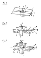
- the fluid guide body 1 which consist of plastic and in particular can be injection molded, a main channel 2, which is integral in the fluid guide body 1 is incorporated and is open to one side.
- the open one Side of the main channel 2 is covered with a cover sheet 3, which is not shown in FIG is in particular designed as an elastic membrane made of plastic, closed, as will be explained in connection with Figures 2 and 3.
- the fluid guide body 1 also has a secondary channel 4, which is from the rear of the fluid guide body 1 facing away from the open side of the main channel 2 leads to the opposite front of the fluid guide body 1 and opens into the main channel 2.
- the secondary channel 4 passes through the bottom 5 of the main channel.
- Secondary channel 4 in the form of a volcanic chimney 6, the height of which is the depth of the Main channel corresponds so that a mouth 7 of the secondary channel 4 is flush is arranged with the edges of the main channel 2.
- the secondary channel 4 is symmetrical in the middle of the main channel 2 and extends perpendicular to the longitudinal direction of the main channel 2.
- the mouth just formed 7 lies in the plane spanned by the edges of the main channel 2 becomes.
- the chimney 6 has a streamlined cross section. More accurate said the outside of the wall of the secondary duct 4 in the main duct 2 streamlined, the longitudinal axis of the streamlined shape of the Longitudinal axis of the main channel 2 corresponds. This creates turbulence, Turbulence and an increased flow resistance at the secondary channel avoided.
- the medical fluid flowing through the main channel 2 can be laminar flow past the secondary channel 4.
- the contours of the main channel 2 are also around the secondary channel 4 streamlined around.
- the opposite of the chimney 6 Side walls of the main channel 2 are streamlined around the chimney 6 bulged, so that the bifurcating liquid flow around the chimney 6 finds approximately the same flow cross-section and without major ones Changes in speed can flow past this.
- the cover film lies on the fluid guide body 1 3, which is welded along the circumference to the fluid guide body 1 or can be connected in a similar manner.
- the main duct 2 can cover 3 along the edges of the main channel 2 with the fluid guide body 1 be welded.
- the seal can also be pressed on the cover sheet 3 by means of a valve stamp 8 along the edges of the Main channel 2 are effected.
- the valve stamp 8 has a continuous, flat stamp surface 9, which an elastic machine membrane preferably formed from an elastomer becomes. Due to the flush arrangement of the mouth 7 with the edges of the Main channel 2 can close the secondary channel 7 without stretching the cover film 3 when the cover sheet 3 is pressed onto the fluid guide body 1 as a whole becomes.
- the mouth 7 is designed as a flat valve seat 10, the in the plane spanned by the edges of the main channel 2 and the front End of the chimney 6 forms.
- the stamp surface 9 is pressed onto the fluid guide body 1 as a whole.
- additional Pressure is applied to securely seal the secondary duct 4 to reach.
- the actuating part 11, which with the stamp surface 9 is connected in the area of the secondary channel mouth 7 by the fluid guide body 1 moved away.
- the stamp surface 9 in the area of Mouth 7 of the secondary channel 4 is lifted from this. 3 shows deformed the stamp surface 9, which is due to the formation of the same as elastic Membrane is made possible.
- the cover 3 By lifting the stamp surface 9, the cover 3 also lifts from the Mouth 7 of the secondary channel 4.
- the pressure of the flow in the main channel 2 presses the cover sheet 3 away from the mouth 7. If necessary, this can also be the case active by interposing a vacuum between the stamp surface 9 and the cover sheet 3 are supported, which is particularly helpful when a sample from the liquid flow in the main channel 2 through the secondary channel 4 should be suctioned off.
- the cover sheet 3 When lifting off the mouth 7, the cover sheet 3 expands elastically. The deformation is very small. In particular, it is not plastic, so that prevents creasing during the subsequent reclosing of the mouth 7 is. As shown in FIG. 3, the cover film 3 is the secondary channel in the raised state 4 flow-connected to the main channel 2.
- FIG. 4 Another embodiment of the invention is shown in FIG. 4, in which corresponding parts marked with the same reference numbers as in the previously described embodiment are.
- the secondary channel 4 does not open in the form of a volcanic chimney in the main channel 2. Rather, the main channel 2 and the secondary channel 4, both, the secondary channel 4 at least partially, in the fluid guide body 1 are designed as an open groove, only by one another Web 12 separated, which forms a side wall of the main channel 2 and this continues to the adjacent areas (see Figure 4).
- the secondary channel extends vertically towards the main channel 2 in the embodiment shown, the cross section of the secondary channel 4 preferably toward the separating web 12 expanded like a delta.
- Lifting the elastomeric cover film (as well as possibly the elastomeric machine stamp cover membrane) is similar to opening lips: there foil and The membrane must not be overstretched in order to close it later without wrinkles can, the opening stroke is relatively small and the opening width is relatively large. Therefore the delta-shaped extension of the normally narrow secondary channel.
- the connection of the secondary duct 4 to the main duct 2 is controlled by the cover film 3, which lies on the fluid guide body 1 and spans the open sides of the secondary duct 4 and the main duct 2.
- the cover film is not shown in Figure 4.
- the cover film can be welded to the fluid guide body 1 around the main channel 2 with the recess in the separating web 12 and around the secondary channel 4.
- the cover film can also be pressed against the surface of the fluid guide body 1 by a valve stamp, which can be formed by a machine block, as previously described.
- a valve actuator or the actuating part 11 is provided, which sits in the region of the web 12 on the fluid guide body 1 and presses the cover film onto the web 12.
- the film can be moved away from the web 12, so that the main channel 2 also passes over it the secondary channel 4 is brought into flow connection.
- the machine block 11 is shown in section in FIG. 4 and extends over the entire surface of the fluid guide body 1, in which the channels are exposed.
- the main channel flow remains from the secondary channel 4 or its mouth completely unaffected.
- the closed position i.e. H. when the actuating part 11 is pressed onto the fluid guide body 1, is from the View of the flow through the main channel, no valve or no secondary channel available, so that optimal flow conditions can be achieved.
Landscapes
- Health & Medical Sciences (AREA)
- Heart & Thoracic Surgery (AREA)
- Vascular Medicine (AREA)
- Life Sciences & Earth Sciences (AREA)
- General Health & Medical Sciences (AREA)
- Anesthesiology (AREA)
- Biomedical Technology (AREA)
- Hematology (AREA)
- Veterinary Medicine (AREA)
- Animal Behavior & Ethology (AREA)
- Engineering & Computer Science (AREA)
- Public Health (AREA)
- Cardiology (AREA)
- Pulmonology (AREA)
- External Artificial Organs (AREA)
- Infusion, Injection, And Reservoir Apparatuses (AREA)
- Separation Using Semi-Permeable Membranes (AREA)
- Packages (AREA)
Abstract
Description
- Fig. 1:
- eine perspektivische Ansicht eines Fluidführungskorpus mit einem offenen Haupkanal und einem darin einmündenden Nebenkanal gemäß einer bevorzugten Ausführung der Erfindung in einer ausschnittsweisen Darstellung,
- Fig. 2:
- eine perspektivische Ansicht des Fluidführungskorpus aus Fig. 1 in einem Teilschnitt, wobei eine Abdeckfolie mittels eines Ventilaktors auf den Fluidführungskorpus gedrückt ist und den Nebenkanal verschließt,
- Fig. 3:
- eine perspektivische Ansicht ähnlich Fig. 2, wobei der Nebenkanal in seiner geöffneten Stellung dargestellt ist, und
- Fig. 4:
- eine perspektivische Ansicht eines Fluidführungskorpus mit einem offenen Hauptkanal und einem in diesen mündenden Nebenkanal gemäß einer weiteren bevorzugten Ausführung der Erfindung.
dem Nebenkanal 4 in Strömungsverbindung gebracht wird. Es versteht sich, daß in der Figur 4 der Maschinenblock 11 geschnitten dargestellt ist und sich über die gesamte Fläche des Fluidführungskorpus 1, in der die Kanäle offen zu Tage treten, erstreckt.
Claims (18)
- Vorrichtung zur Zuführung und/oder Abzweigung einer Nebenströmung in eine und/oder aus einer Hauptströmung einer medizinischen Flüssigkeit, mita.) einem Fluidführungskorpus (1), in dem zumindest ein zu einer Seite offener Hauptkanal (2) sowie zumindest ein Nebenkanal (4), der eine mit dem Hauptkanal (2) in Strömungsverbindung bringbare Mündung (7) besitzt, vorgesehen sind, undb.) einer Abdeckfolie (3), die auf dem Fluidführungskorpus über der offenen Seite des Hauptkanals angeordnet ist,c.) wobei die Mündung (7) des Nebenkanals (4) von der Abdeckfolie (3) verschließbar ist, undd.) wobei der Nebenkanal (4) derart ausgebildet ist, daß der Hauptkanal (2) im Bereich der Mündung (7) des Nebenkanals (4) im wesentlichen totraumfrei ist.
- Vorrichtung nach dem vorhergehenden Anspruch, wobei eine in dem Hauptkanal (2) liegende Außenkontur des Nebenkanals (4) stromlinienförmig ausgebildet ist.
- Vorrichtung nach dem vorhergehenden Anspruch, wobei die in dem Hauptkanal (2) liegende Außenkontur des Nebenkanals (4) eine spitzwinklig zulaufende Abrißkante und/oder eine abgerundete Anströmkante besitzt.
- Vorrichtung nach einem der beiden vorhergehenden Ansprüche, wobei sich die in dem Hauptkanal (2) liegende Außenkontur des Nebenkanals in Richtung der Hauptkanalströmung zumindest doppelt so lang erstreckt wie in Richtung quer zu der Hauptkanalströmung.
- Vorrichtung nach einem der vorhergehenden Ansprüche, wobei die Mündung (7) des Nebenkanals (4) einen ebenen, flachen Ventilsitz (10) aufweist.
- Vorrichtung nach einem der vorhergehenden Ansprüche, wobei die Mündung (7) des Nebenkanals (4) in der von den angrenzenden Rändern des Hauptkanals aufgespannten Ebene angeordnet ist.
- Vorrichtung nach einem der vorhergehenden Ansprüche, wobei der Nebenkanal (4) mit seiner Längsachse senkrecht auf die Strömungsrichtung der Hauptströmung, insbesondere senkrecht auf die Abdeckfolie (3) mündet.
- Vorrichtung nach einem der vorhergehenden Ansprüche, wobei der Nebenkanal (4) im Hauptkanal (2) einen Schlot (6) bildet, der sich vom Boden (5) des Hauptkanals (2) bis zu dessen offener Seite erstreckt.
- Vorrichtung nach einem der vorhergehenden Ansprüche, wobei der Nebenkanal (4) symmetrisch im Hauptkanal (2) angeordnet ist.
- Vorrichtung nach einem der vorhergehenden Ansprüche, wobei der Hauptkanal (2) um den Nebenkanal (4) herum derart geformt ist, daß der Strömungsquerschnitt im Hauptkanal in etwa konstant ist.
- Vorrichtung nach einem der vorhergehenden Ansprüche 1-9, wobei der Hauptkanal (2) im Bereich der Mündung (7) des Nebenkanals (4) einen größeren Strömungsquerschnitt als stromauf und stromab der Mündung des Nebenkanals (4) besitzt.
- Vorrichtung nach einem der vorhergehenden Ansprüche, wobei der Nebenkanal (4) auf die der offenen Seite des Hauptkanals gegenüberliegende Rückseite des Fluidführungskorpus (1) geführt ist.
- Vorrichtung nach einem der vorhergehenden Ansprüche, wobei die Abdeckfolie (3) aus Kunststoff besteht, insbesondere von einer elastischen Membran gebildet ist.
- Vorrichtung nach einem der vorhergehenden Ansprüche, wobei der Fluidführungskorpus (1) mit der Abdeckfolie (3) eine Disposablekassette bildet, die in eine Maschine zur extrakorporalen Blutbehandlung, insbesondere eine Dialysemaschine, einsetzbar ist.
- Verwendung der Vorrichtung nach einem der vorhergehenden Ansprüche zur Zuführung einer medizinischen Flüssigkeit in einen extrakorporalen Blutstrom und/oder zur Entnahme einer Probe aus einem extrakorporalen Blutstrom.
- Ventilaktor für die Vorrichtung nach einem der Ansprüche 1 bis 14, mit einer Hauptstempelfläche zum Andrücken der Abdeckfolie (3) an die Ränder des Hauptkanales (2) und einer Nebenstempelfläche zum Andrücken der Abdeckfolie (3) auf die Mündung (7) des Nebenkanals (4), wobei die Hauptstempelfläche und die Nebenstempelfläche in derselben Ebene liegen, und wobei bildet ist und ein Betätigungsteil (1)1 zur Betätigung der Nebenstempelfläche vorgesehen ist.
- Ventilaktor nach dem vorhergehenden Anspruch, wobei die Hauptstempelfläche und die Nebenstempelfläche von einer gemeinsamen ebenen Stempelfläche (9), insbesondere von einer Elastomerplatte gebildet sind.
- Medizinisches Fluidsystem umfassend eine Vorrichtung nach einem der Ansprüche 1-14 sowie einen Ventilaktor nach einem der Ansprüche 16 oder 17.
Applications Claiming Priority (2)
| Application Number | Priority Date | Filing Date | Title |
|---|---|---|---|
| DE10053441 | 2000-10-27 | ||
| DE2000153441 DE10053441B4 (de) | 2000-10-27 | 2000-10-27 | Disposablekassette mit Dichtungsmembran sowie Ventilaktor hierfür |
Publications (2)
| Publication Number | Publication Date |
|---|---|
| EP1201264A1 true EP1201264A1 (de) | 2002-05-02 |
| EP1201264B1 EP1201264B1 (de) | 2006-11-29 |
Family
ID=7661355
Family Applications (1)
| Application Number | Title | Priority Date | Filing Date |
|---|---|---|---|
| EP20010125165 Expired - Lifetime EP1201264B1 (de) | 2000-10-27 | 2001-10-23 | Wegwerfbare Kassette mit Dichtungsmembran |
Country Status (8)
| Country | Link |
|---|---|
| US (1) | US6752172B2 (de) |
| EP (1) | EP1201264B1 (de) |
| JP (1) | JP3965290B2 (de) |
| AT (1) | ATE346647T1 (de) |
| DE (2) | DE10053441B4 (de) |
| DK (1) | DK1201264T3 (de) |
| ES (1) | ES2275605T3 (de) |
| PT (1) | PT1201264E (de) |
Cited By (7)
| Publication number | Priority date | Publication date | Assignee | Title |
|---|---|---|---|---|
| WO2009006504A3 (en) * | 2007-07-05 | 2009-06-04 | Baxter Int | Dialysis cassette having multiple outlet valve |
| EP2298378A3 (de) * | 2002-12-31 | 2013-05-01 | Baxter International Inc. | System für die Peritonealdialyse |
| EP2368589A3 (de) * | 2003-10-28 | 2014-01-15 | Baxter International Inc. | Vorrichtung für medizinische Flüssigkeitssysteme |
| EP3088019A1 (de) * | 2015-04-30 | 2016-11-02 | Ulrich GmbH & Co. KG | Vorrichtung zum transfer eines fluids |
| US9675744B2 (en) | 2002-05-24 | 2017-06-13 | Baxter International Inc. | Method of operating a disposable pumping unit |
| US9775939B2 (en) | 2002-05-24 | 2017-10-03 | Baxter International Inc. | Peritoneal dialysis systems and methods having graphical user interface |
| IT202000030338A1 (it) | 2020-12-10 | 2022-06-10 | Baxter Int | Apparato medicale |
Families Citing this family (92)
| Publication number | Priority date | Publication date | Assignee | Title |
|---|---|---|---|---|
| CA2347537C (en) * | 1999-09-03 | 2009-01-20 | Baxter International Inc. | Programmable, fluid pressure actuated blood processing systems and methods |
| US6497676B1 (en) | 2000-02-10 | 2002-12-24 | Baxter International | Method and apparatus for monitoring and controlling peritoneal dialysis therapy |
| DE10224750A1 (de) | 2002-06-04 | 2003-12-24 | Fresenius Medical Care De Gmbh | Vorrichtung zur Behandlung einer medizinischen Flüssigkeit |
| EP1523347B1 (de) * | 2002-07-19 | 2011-05-18 | Baxter International Inc. | Vorrichtungen und verfahren zur peritonealdialyse |
| DE10239597B4 (de) * | 2002-08-28 | 2005-03-17 | Fresenius Medical Care Deutschland Gmbh | Einwegkassette |
| JP4589319B2 (ja) † | 2003-07-31 | 2010-12-01 | デビオテック ソシエテ アノニム | 腹膜透析システム |
| US8029454B2 (en) | 2003-11-05 | 2011-10-04 | Baxter International Inc. | High convection home hemodialysis/hemofiltration and sorbent system |
| US8038639B2 (en) | 2004-11-04 | 2011-10-18 | Baxter International Inc. | Medical fluid system with flexible sheeting disposable unit |
| US7935074B2 (en) | 2005-02-28 | 2011-05-03 | Fresenius Medical Care Holdings, Inc. | Cassette system for peritoneal dialysis machine |
| US8197231B2 (en) | 2005-07-13 | 2012-06-12 | Purity Solutions Llc | Diaphragm pump and related methods |
| US12421952B2 (en) | 2013-03-15 | 2025-09-23 | Deka Products Limited Partnership | Reciprocating diaphragm pumps for blood treatment systems and methods |
| US10537671B2 (en) | 2006-04-14 | 2020-01-21 | Deka Products Limited Partnership | Automated control mechanisms in a hemodialysis apparatus |
| CA3123166A1 (en) | 2006-04-14 | 2007-10-25 | Deka Products Limited Partnership | Systems, devices and methods for fluid pumping, heat exchange, thermal sensing, and conductivity sensing |
| US8366316B2 (en) | 2006-04-14 | 2013-02-05 | Deka Products Limited Partnership | Sensor apparatus systems, devices and methods |
| US9028691B2 (en) | 2007-02-27 | 2015-05-12 | Deka Products Limited Partnership | Blood circuit assembly for a hemodialysis system |
| US8888470B2 (en) | 2007-02-27 | 2014-11-18 | Deka Products Limited Partnership | Pumping cassette |
| US8042563B2 (en) | 2007-02-27 | 2011-10-25 | Deka Products Limited Partnership | Cassette system integrated apparatus |
| US8562834B2 (en) | 2007-02-27 | 2013-10-22 | Deka Products Limited Partnership | Modular assembly for a portable hemodialysis system |
| US8409441B2 (en) | 2007-02-27 | 2013-04-02 | Deka Products Limited Partnership | Blood treatment systems and methods |
| US20090107335A1 (en) | 2007-02-27 | 2009-04-30 | Deka Products Limited Partnership | Air trap for a medical infusion device |
| US8357298B2 (en) | 2007-02-27 | 2013-01-22 | Deka Products Limited Partnership | Hemodialysis systems and methods |
| US8425471B2 (en) | 2007-02-27 | 2013-04-23 | Deka Products Limited Partnership | Reagent supply for a hemodialysis system |
| KR20230165373A (ko) | 2007-02-27 | 2023-12-05 | 데카 프로덕츠 리미티드 파트너쉽 | 혈액투석 시스템 |
| US8393690B2 (en) | 2007-02-27 | 2013-03-12 | Deka Products Limited Partnership | Enclosure for a portable hemodialysis system |
| US8491184B2 (en) | 2007-02-27 | 2013-07-23 | Deka Products Limited Partnership | Sensor apparatus systems, devices and methods |
| US7736328B2 (en) | 2007-07-05 | 2010-06-15 | Baxter International Inc. | Dialysis system having supply container autoconnection |
| US8496609B2 (en) | 2007-07-05 | 2013-07-30 | Baxter International Inc. | Fluid delivery system with spiked cassette |
| US7955295B2 (en) | 2007-07-05 | 2011-06-07 | Baxter International Inc. | Fluid delivery system with autoconnect features |
| US8057423B2 (en) | 2007-07-05 | 2011-11-15 | Baxter International Inc. | Dialysis system having disposable cassette |
| US8715235B2 (en) * | 2007-07-05 | 2014-05-06 | Baxter International Inc. | Dialysis system having disposable cassette and heated cassette interface |
| US7909795B2 (en) * | 2007-07-05 | 2011-03-22 | Baxter International Inc. | Dialysis system having disposable cassette and interface therefore |
| US8105487B2 (en) | 2007-09-25 | 2012-01-31 | Fresenius Medical Care Holdings, Inc. | Manifolds for use in conducting dialysis |
| US9308307B2 (en) | 2007-09-13 | 2016-04-12 | Fresenius Medical Care Holdings, Inc. | Manifold diaphragms |
| US8240636B2 (en) | 2009-01-12 | 2012-08-14 | Fresenius Medical Care Holdings, Inc. | Valve system |
| US8597505B2 (en) | 2007-09-13 | 2013-12-03 | Fresenius Medical Care Holdings, Inc. | Portable dialysis machine |
| US9358331B2 (en) | 2007-09-13 | 2016-06-07 | Fresenius Medical Care Holdings, Inc. | Portable dialysis machine with improved reservoir heating system |
| EP2246080B1 (de) * | 2007-10-12 | 2016-02-10 | DEKA Products Limited Partnership | Extrakorporaler blutkreislauf |
| US8771508B2 (en) | 2008-08-27 | 2014-07-08 | Deka Products Limited Partnership | Dialyzer cartridge mounting arrangement for a hemodialysis system |
| US8114276B2 (en) | 2007-10-24 | 2012-02-14 | Baxter International Inc. | Personal hemodialysis system |
| EP2237814B1 (de) | 2007-11-29 | 2019-03-06 | Fresenius Medical Care Holdings, Inc. | Verteileranordnung zur durchführung von hämodialyse und hämofiltration |
| US11975128B2 (en) | 2008-01-23 | 2024-05-07 | Deka Products Limited Partnership | Medical treatment system and methods using a plurality of fluid lines |
| US11738130B2 (en) | 2008-01-23 | 2023-08-29 | Deka Products Limited Partnership | Fluid line autoconnect apparatus and methods for medical treatment system |
| WO2009094184A1 (en) | 2008-01-23 | 2009-07-30 | Deka Products Limited Partnership | Fluid volume determination for medical treatment system |
| US9078971B2 (en) | 2008-01-23 | 2015-07-14 | Deka Products Limited Partnership | Medical treatment system and methods using a plurality of fluid lines |
| US11833281B2 (en) | 2008-01-23 | 2023-12-05 | Deka Products Limited Partnership | Pump cassette and methods for use in medical treatment system using a plurality of fluid lines |
| US8062513B2 (en) | 2008-07-09 | 2011-11-22 | Baxter International Inc. | Dialysis system and machine having therapy prescription recall |
| US9514283B2 (en) | 2008-07-09 | 2016-12-06 | Baxter International Inc. | Dialysis system having inventory management including online dextrose mixing |
| CA2976872C (en) | 2008-10-07 | 2021-04-13 | Fresenius Medical Care Holdings, Inc. | Priming system and method for dialysis systems |
| NZ592652A (en) | 2008-10-30 | 2013-10-25 | Fresenius Med Care Hldg Inc | Modular, portable dialysis system |
| DE102009012633A1 (de) | 2009-03-10 | 2010-09-23 | Fresenius Medical Care Deutschland Gmbh | Vorrichtung zum Verbinden einer externen Funktionseinrichtung mit einer Anordnung, Anordnung aufweisend eine solche Vorrichtung und Verfahren zum Verbinden |
| US8192401B2 (en) | 2009-03-20 | 2012-06-05 | Fresenius Medical Care Holdings, Inc. | Medical fluid pump systems and related components and methods |
| WO2010114932A1 (en) | 2009-03-31 | 2010-10-07 | Xcorporeal, Inc. | Modular reservoir assembly for a hemodialysis and hemofiltration system |
| KR101753134B1 (ko) * | 2009-04-23 | 2017-07-03 | 프레제니우스 메디칼 케어 도이칠란드 게엠베하 | 외부 기능 장치, 이 외부 기능 장치를 수용하기 위한 혈액 처리 장치 및 방법 |
| JP5657643B2 (ja) * | 2009-04-23 | 2015-01-21 | フレゼニウス メディカル ケア ドイッチェランド ゲゼルシャフト ミット ベシュレンクテル ハフツング | バルブ装置、バルブ挿入体、外部機能手段、処理機器、および、方法 |
| WO2011008858A1 (en) | 2009-07-15 | 2011-01-20 | Fresenius Medical Care Holdings, Inc. | Medical fluid cassettes and related systems and methods |
| US8720913B2 (en) | 2009-08-11 | 2014-05-13 | Fresenius Medical Care Holdings, Inc. | Portable peritoneal dialysis carts and related systems |
| JP2013509271A (ja) | 2009-10-30 | 2013-03-14 | デカ・プロダクツ・リミテッド・パートナーシップ | 血管アクセスデバイスの離脱を検知するための装置および方法 |
| US8425780B2 (en) | 2010-03-11 | 2013-04-23 | Fresenius Medical Care Holdings, Inc. | Dialysis system venting devices and related systems and methods |
| JP5828410B2 (ja) * | 2010-03-19 | 2015-12-02 | カムボウリス,アムブロシオス | バルブアセンブリ |
| WO2012006425A2 (en) | 2010-07-07 | 2012-01-12 | Deka Products Limited Partnership | Medical treatment system and methods using a plurality of fluid lines |
| DE102010053973A1 (de) | 2010-12-09 | 2012-06-14 | Fresenius Medical Care Deutschland Gmbh | Medizinisches Gerät mit einer Heizung |
| US9694125B2 (en) | 2010-12-20 | 2017-07-04 | Fresenius Medical Care Holdings, Inc. | Medical fluid cassettes and related systems and methods |
| US9624915B2 (en) | 2011-03-09 | 2017-04-18 | Fresenius Medical Care Holdings, Inc. | Medical fluid delivery sets and related systems and methods |
| CN103648540B (zh) | 2011-04-21 | 2016-06-01 | 弗雷塞尼斯医疗保健控股公司 | 医疗流体泵送系统及相关装置和方法 |
| JP6109819B2 (ja) | 2011-05-24 | 2017-04-05 | デカ・プロダクツ・リミテッド・パートナーシップ | 血液透析システム |
| EP2714123B1 (de) | 2011-05-24 | 2017-08-09 | DEKA Products Limited Partnership | Blutbehandlungssysteme und -verfahren |
| US9186449B2 (en) | 2011-11-01 | 2015-11-17 | Fresenius Medical Care Holdings, Inc. | Dialysis machine support assemblies and related systems and methods |
| EP3002989B1 (de) | 2011-11-04 | 2017-04-19 | DEKA Products Limited Partnership | Medizinisches behandlungssystem und verfahren anhand der verwendung mehrerer flüssigkeitsleitungen |
| US9610392B2 (en) | 2012-06-08 | 2017-04-04 | Fresenius Medical Care Holdings, Inc. | Medical fluid cassettes and related systems and methods |
| US9500188B2 (en) | 2012-06-11 | 2016-11-22 | Fresenius Medical Care Holdings, Inc. | Medical fluid cassettes and related systems and methods |
| US9201036B2 (en) | 2012-12-21 | 2015-12-01 | Fresenius Medical Care Holdings, Inc. | Method and system of monitoring electrolyte levels and composition using capacitance or induction |
| US9157786B2 (en) | 2012-12-24 | 2015-10-13 | Fresenius Medical Care Holdings, Inc. | Load suspension and weighing system for a dialysis machine reservoir |
| US9561323B2 (en) | 2013-03-14 | 2017-02-07 | Fresenius Medical Care Holdings, Inc. | Medical fluid cassette leak detection methods and devices |
| US10117985B2 (en) | 2013-08-21 | 2018-11-06 | Fresenius Medical Care Holdings, Inc. | Determining a volume of medical fluid pumped into or out of a medical fluid cassette |
| US9354640B2 (en) * | 2013-11-11 | 2016-05-31 | Fresenius Medical Care Holdings, Inc. | Smart actuator for valve |
| DE102014102598A1 (de) | 2014-02-27 | 2015-08-27 | Fresenius Medical Care Deutschland Gmbh | Blutbehandlungskassette mit Sterilisationsöffnung und zugehörigem Verschluss sowie Blutbehandlungsvorrichtung |
| DE102014103491A1 (de) | 2014-03-14 | 2015-09-17 | Fresenius Medical Care Deutschland Gmbh | Blutbehandlungskassette mit Folienventil und unelastischem Abstandhalter sowie Blutbehandlungsvorrichtung |
| DE102014103507A1 (de) | 2014-03-14 | 2015-09-17 | Fresenius Medical Care Deutschland Gmbh | Medizinische Funktionsvorrichtung mit einem Ventilsitz für ein remanentes Rückschlagventil |
| DE102014103490A1 (de) | 2014-03-14 | 2015-09-17 | Fresenius Medical Care Deutschland Gmbh | Blutbehandlungskassette mit Folienventil und elastischem Abstandhalter sowie Blutbehandlungsvorrichtung |
| DE102014103492A1 (de) | 2014-03-14 | 2015-09-17 | Fresenius Medical Care Deutschland Gmbh | Flüssigkeitskassette mit kipptoleranter Zentrierverrastung sowie Blutbehandlungsvorrichtung |
| DE102014103508B4 (de) * | 2014-03-14 | 2019-04-18 | Fresenius Medical Care Deutschland Gmbh | Vorgespanntes Ventil für medizinische Funktionsvorrichtung, und medizinische Funktionsvorrichtung |
| DE102014103506A1 (de) | 2014-03-14 | 2015-09-17 | Fresenius Medical Care Deutschland Gmbh | Blutbehandlungskassette mit gedelltem Folienventil sowie Blutbehandlungsvorrichtung |
| DE102015016023A1 (de) * | 2015-12-11 | 2017-06-14 | Fresenius Medical Care Deutschland Gmbh | Sperr- und/oder Drosselventil und Blutbehandlungsgerät umfassend ein derartiges Ventil |
| US9889244B2 (en) | 2015-12-17 | 2018-02-13 | Fresenius Medical Care Holdings, Inc. | System and method for controlling venous air recovery in a portable dialysis system |
| AU2017231675B2 (en) | 2016-03-08 | 2022-03-31 | Fresenius Medical Care Holdings, Inc. | Methods and system of generating rapidly varying pressure amplitudes in fluidic circuits in a dialysis treatment system |
| JP6946318B2 (ja) | 2016-03-08 | 2021-10-06 | フレセニウス メディカル ケア ホールディングス インコーポレーテッド | 透析システムの血液回路中の閉塞を検出するための方法およびシステム |
| US10561778B2 (en) | 2017-03-02 | 2020-02-18 | Fresenius Medical Care Holdings, Inc. | Split reservoir bags and method of using split reservoir bags to improve the heating and generation of dialysate |
| US11110214B2 (en) | 2017-04-07 | 2021-09-07 | Fresenius Medical Care Holdings, Inc. | Methods and systems for measuring and heating dialysate |
| US11179516B2 (en) | 2017-06-22 | 2021-11-23 | Baxter International Inc. | Systems and methods for incorporating patient pressure into medical fluid delivery |
| CA3095364C (en) | 2018-03-30 | 2026-05-05 | Deka Products Limited Partnership | Liquid pumping cassettes, pressure distribution manifold, and related methods |
| EP3793635B1 (de) | 2018-07-27 | 2023-12-27 | Fresenius Medical Care Holdings, Inc. | System und verfahren zur personalisierung einer dialysebehandlung |
| DE102020216088A1 (de) * | 2020-12-16 | 2022-06-23 | Fraunhofer-Gesellschaft zur Förderung der angewandten Forschung eingetragener Verein | Modulare Bestrahlungsvorrichtung und Bestrahlungsverfahren |
Citations (6)
| Publication number | Priority date | Publication date | Assignee | Title |
|---|---|---|---|---|
| US5062774A (en) * | 1989-12-01 | 1991-11-05 | Abbott Laboratories | Solution pumping system including disposable pump cassette |
| US5098262A (en) * | 1990-12-28 | 1992-03-24 | Abbott Laboratories | Solution pumping system with compressible pump cassette |
| US5203368A (en) * | 1992-07-29 | 1993-04-20 | Protein Technologies Inc. | Matrix of valves |
| US5722946A (en) * | 1995-06-07 | 1998-03-03 | Cobe Laboratories, Inc. | Extracorporeal blood processing methods and apparatus |
| US5803105A (en) * | 1995-11-20 | 1998-09-08 | Argonaut Technologies, Inc. | Systems and methods for distributing fluids |
| DE19718963C1 (de) * | 1997-05-05 | 1999-02-18 | Heinzl Joachim | Fluidmechanisches Steuerglied |
Family Cites Families (7)
| Publication number | Priority date | Publication date | Assignee | Title |
|---|---|---|---|---|
| US4703913A (en) * | 1982-09-22 | 1987-11-03 | California Institute Of Technology | Diaphragm valve |
| US4597412A (en) * | 1982-09-29 | 1986-07-01 | Stark Anton W | Valve for sequential chemical operations |
| US4558715A (en) * | 1984-05-16 | 1985-12-17 | Kowatachi International, Ltd. | Apparatus for injecting measured quantities of liquid into a fluid stream |
| US5161773A (en) * | 1990-08-01 | 1992-11-10 | Numed, Inc. | Method and apparatus for controlling fluid flow |
| DE4336336A1 (de) * | 1992-11-23 | 1994-05-26 | Lang Volker | Kasetteninfusionssystem |
| US5738662A (en) * | 1996-02-21 | 1998-04-14 | Pacific Device/Avail Medical Products, Inc. | Retrograde flow checked manifold for infusing medical fluids |
| DE19622050A1 (de) * | 1996-05-31 | 1997-12-04 | Lang Volker | Kassetten-Mikroverteiler mit besonderer Eignung für die Infusionstherapie |
-
2000
- 2000-10-27 DE DE2000153441 patent/DE10053441B4/de not_active Expired - Lifetime
-
2001
- 2001-10-23 AT AT01125165T patent/ATE346647T1/de active
- 2001-10-23 PT PT01125165T patent/PT1201264E/pt unknown
- 2001-10-23 JP JP2001324839A patent/JP3965290B2/ja not_active Expired - Lifetime
- 2001-10-23 DE DE50111532T patent/DE50111532D1/de not_active Expired - Lifetime
- 2001-10-23 DK DK01125165T patent/DK1201264T3/da active
- 2001-10-23 EP EP20010125165 patent/EP1201264B1/de not_active Expired - Lifetime
- 2001-10-23 ES ES01125165T patent/ES2275605T3/es not_active Expired - Lifetime
- 2001-10-29 US US09/984,160 patent/US6752172B2/en not_active Expired - Lifetime
Patent Citations (6)
| Publication number | Priority date | Publication date | Assignee | Title |
|---|---|---|---|---|
| US5062774A (en) * | 1989-12-01 | 1991-11-05 | Abbott Laboratories | Solution pumping system including disposable pump cassette |
| US5098262A (en) * | 1990-12-28 | 1992-03-24 | Abbott Laboratories | Solution pumping system with compressible pump cassette |
| US5203368A (en) * | 1992-07-29 | 1993-04-20 | Protein Technologies Inc. | Matrix of valves |
| US5722946A (en) * | 1995-06-07 | 1998-03-03 | Cobe Laboratories, Inc. | Extracorporeal blood processing methods and apparatus |
| US5803105A (en) * | 1995-11-20 | 1998-09-08 | Argonaut Technologies, Inc. | Systems and methods for distributing fluids |
| DE19718963C1 (de) * | 1997-05-05 | 1999-02-18 | Heinzl Joachim | Fluidmechanisches Steuerglied |
Cited By (15)
| Publication number | Priority date | Publication date | Assignee | Title |
|---|---|---|---|---|
| US9675744B2 (en) | 2002-05-24 | 2017-06-13 | Baxter International Inc. | Method of operating a disposable pumping unit |
| US9775939B2 (en) | 2002-05-24 | 2017-10-03 | Baxter International Inc. | Peritoneal dialysis systems and methods having graphical user interface |
| US10525184B2 (en) | 2002-07-19 | 2020-01-07 | Baxter International Inc. | Dialysis system and method for pumping and valving according to flow schedule |
| US9795729B2 (en) | 2002-07-19 | 2017-10-24 | Baxter International Inc. | Pumping systems for cassette-based dialysis |
| EP2298378A3 (de) * | 2002-12-31 | 2013-05-01 | Baxter International Inc. | System für die Peritonealdialyse |
| US10117986B2 (en) | 2003-10-28 | 2018-11-06 | Baxter International Inc. | Peritoneal dialysis machine |
| EP2368589A3 (de) * | 2003-10-28 | 2014-01-15 | Baxter International Inc. | Vorrichtung für medizinische Flüssigkeitssysteme |
| WO2009006504A3 (en) * | 2007-07-05 | 2009-06-04 | Baxter Int | Dialysis cassette having multiple outlet valve |
| EP3088019A1 (de) * | 2015-04-30 | 2016-11-02 | Ulrich GmbH & Co. KG | Vorrichtung zum transfer eines fluids |
| CN106075630B (zh) * | 2015-04-30 | 2019-09-06 | 乌尔里希有限及两合公司 | 用于传输液体的装置、具有该装置的卡盒和液体输送装置 |
| RU2702606C2 (ru) * | 2015-04-30 | 2019-10-08 | Ульрих Гмбх Унд Ко. Кг | Устройство для транспортировки текучей среды, кассета для вставления в устройство подачи текучей среды и устройство для подачи текучей среды |
| CN106075630A (zh) * | 2015-04-30 | 2016-11-09 | 乌尔里希有限及两合公司 | 用于传输液体的装置、具有该装置的卡盒和液体输送装置 |
| IT202000030338A1 (it) | 2020-12-10 | 2022-06-10 | Baxter Int | Apparato medicale |
| WO2022123020A1 (en) | 2020-12-10 | 2022-06-16 | Baxter Healthcare Sa | Medical apparatus |
| US12544496B2 (en) | 2020-12-10 | 2026-02-10 | Baxter International Inc. | Medical apparatus |
Also Published As
| Publication number | Publication date |
|---|---|
| DE10053441B4 (de) | 2004-04-15 |
| EP1201264B1 (de) | 2006-11-29 |
| PT1201264E (pt) | 2007-01-31 |
| JP2002177383A (ja) | 2002-06-25 |
| US6752172B2 (en) | 2004-06-22 |
| US20020062109A1 (en) | 2002-05-23 |
| DE10053441A1 (de) | 2002-05-16 |
| DE50111532D1 (de) | 2007-01-11 |
| DK1201264T3 (da) | 2006-12-27 |
| ES2275605T3 (es) | 2007-06-16 |
| ATE346647T1 (de) | 2006-12-15 |
| JP3965290B2 (ja) | 2007-08-29 |
Similar Documents
| Publication | Publication Date | Title |
|---|---|---|
| DE10053441B4 (de) | Disposablekassette mit Dichtungsmembran sowie Ventilaktor hierfür | |
| EP1440732B1 (de) | Mikrofluidische Anordnung zum Dosieren von Flüssigkeiten | |
| DE69411568T2 (de) | Selbstentlüftende filtervorrichtung | |
| EP1509260B1 (de) | Vorrichtung zur behandlung einer medizinischen flüssigkeit | |
| DE3837498C2 (de) | ||
| EP1944084B1 (de) | Ventilvorrichtung für ein Mikrofluidsystem | |
| EP2146774B1 (de) | Drainageschlaucheinheit | |
| DE10157924C1 (de) | Vorrichtung zur Behandlung einer medizinischen Flüssigkeit | |
| DE69530398T2 (de) | Tropfkammerkopf | |
| DE2605005A1 (de) | Verfahren und vorrichtung zum dosierten zufuehren von antikoagulans | |
| EP3263154B1 (de) | Vorrichtung zur raschen entlüftung und entleerung eines filters | |
| DE2819770A1 (de) | Vorrichtung fuer die zufuhr von fluessigkeit von einem ersten fluessigkeitsbehaelter zu einem zweiten fluessigkeitsbehaelter mittels schwerkraft | |
| DE3035301A1 (de) | Doppelinfusionsvorricvhtung | |
| DE2942803A1 (de) | Filter fuer medizinische fluessigkeiten und verfahren zum einbau eines solchen filters | |
| DE19605217C2 (de) | Infusionsbesteck mit Behältern für Flüssigmedikamente | |
| DE2548255A1 (de) | Vorrichtung zum aufbringen von klebstoff | |
| DE3634357A1 (de) | Verfahren und vorrichtung zur vakuumkompression eines laminats | |
| DE2542198C3 (de) | ||
| DE2913301A1 (de) | Medizinische anschluss- und leitungsanlage fuer eine diffusionsvorrichtung und blasenfalle dafuer | |
| EP3088019A1 (de) | Vorrichtung zum transfer eines fluids | |
| EP4007628B1 (de) | Bidirektional durchströmbare atemgas-ventilbaugruppe und beatmungsvorrichtung mit einer solchen | |
| DE3911587A1 (de) | Vorrichtung und verfahren zur dialyse | |
| DE2500993A1 (de) | Blutentleerungsvorrichtung | |
| DE2844105A1 (de) | Dialysemaschine, insbesondere system zur steuerung eines ventils fuer unterdruck, und alarmsystem fuer den durch die membran hindurch herrschenden druck | |
| EP3318298B1 (de) | Expirationsventil |
Legal Events
| Date | Code | Title | Description |
|---|---|---|---|
| PUAI | Public reference made under article 153(3) epc to a published international application that has entered the european phase |
Free format text: ORIGINAL CODE: 0009012 |
|
| AK | Designated contracting states |
Kind code of ref document: A1 Designated state(s): AT BE CH CY DE DK ES FI FR GB GR IE IT LI LU MC NL PT SE TR |
|
| AX | Request for extension of the european patent |
Free format text: AL;LT;LV;MK;RO;SI |
|
| 17P | Request for examination filed |
Effective date: 20020722 |
|
| AKX | Designation fees paid |
Free format text: AT BE CH CY DE DK ES FI FR GB GR IE IT LI LU MC NL PT SE TR |
|
| 17Q | First examination report despatched |
Effective date: 20040209 |
|
| RTI1 | Title (correction) |
Free format text: DIPOSABLE CASSETTE COMPRISING A SELAING MEMBRANE |
|
| GRAP | Despatch of communication of intention to grant a patent |
Free format text: ORIGINAL CODE: EPIDOSNIGR1 |
|
| GRAS | Grant fee paid |
Free format text: ORIGINAL CODE: EPIDOSNIGR3 |
|
| GRAA | (expected) grant |
Free format text: ORIGINAL CODE: 0009210 |
|
| AK | Designated contracting states |
Kind code of ref document: B1 Designated state(s): AT BE CH CY DE DK ES FI FR GB GR IE IT LI LU MC NL PT SE TR |
|
| REG | Reference to a national code |
Ref country code: GB Ref legal event code: FG4D Free format text: NOT ENGLISH |
|
| REG | Reference to a national code |
Ref country code: SE Ref legal event code: TRGR |
|
| REG | Reference to a national code |
Ref country code: DK Ref legal event code: T3 |
|
| REG | Reference to a national code |
Ref country code: CH Ref legal event code: EP Ref country code: CH Ref legal event code: NV Representative=s name: BOVARD AG PATENTANWAELTE Ref country code: IE Ref legal event code: FG4D Free format text: LANGUAGE OF EP DOCUMENT: GERMAN |
|
| GBT | Gb: translation of ep patent filed (gb section 77(6)(a)/1977) |
Effective date: 20061214 |
|
| REG | Reference to a national code |
Ref country code: IE Ref legal event code: FG4D Free format text: LANGUAGE OF EP DOCUMENT: GERMAN |
|
| REF | Corresponds to: |
Ref document number: 50111532 Country of ref document: DE Date of ref document: 20070111 Kind code of ref document: P |
|
| REG | Reference to a national code |
Ref country code: PT Ref legal event code: SC4A Free format text: AVAILABILITY OF NATIONAL TRANSLATION Effective date: 20061207 |
|
| REG | Reference to a national code |
Ref country code: GR Ref legal event code: EP Ref document number: 20070400561 Country of ref document: GR |
|
| ET | Fr: translation filed | ||
| REG | Reference to a national code |
Ref country code: ES Ref legal event code: FG2A Ref document number: 2275605 Country of ref document: ES Kind code of ref document: T3 |
|
| PLBE | No opposition filed within time limit |
Free format text: ORIGINAL CODE: 0009261 |
|
| STAA | Information on the status of an ep patent application or granted ep patent |
Free format text: STATUS: NO OPPOSITION FILED WITHIN TIME LIMIT |
|
| 26N | No opposition filed |
Effective date: 20070830 |
|
| PG25 | Lapsed in a contracting state [announced via postgrant information from national office to epo] |
Ref country code: MC Free format text: LAPSE BECAUSE OF NON-PAYMENT OF DUE FEES Effective date: 20071031 |
|
| PG25 | Lapsed in a contracting state [announced via postgrant information from national office to epo] |
Ref country code: LU Free format text: LAPSE BECAUSE OF NON-PAYMENT OF DUE FEES Effective date: 20071023 Ref country code: CY Free format text: LAPSE BECAUSE OF FAILURE TO SUBMIT A TRANSLATION OF THE DESCRIPTION OR TO PAY THE FEE WITHIN THE PRESCRIBED TIME-LIMIT Effective date: 20061129 |
|
| REG | Reference to a national code |
Ref country code: CH Ref legal event code: PFA Owner name: FRESENIUS MEDICAL CARE DEUTSCHLAND GMBH Free format text: FRESENIUS MEDICAL CARE DEUTSCHLAND GMBH#ELSE-KROENER-STRASSE 1#61352 BAD HOMBURG V.D.H. (DE) -TRANSFER TO- FRESENIUS MEDICAL CARE DEUTSCHLAND GMBH#ELSE-KROENER-STRASSE 1#61352 BAD HOMBURG V.D.H. (DE) |
|
| REG | Reference to a national code |
Ref country code: FR Ref legal event code: PLFP Year of fee payment: 16 |
|
| PGFP | Annual fee paid to national office [announced via postgrant information from national office to epo] |
Ref country code: FI Payment date: 20160922 Year of fee payment: 16 Ref country code: DK Payment date: 20160922 Year of fee payment: 16 Ref country code: IE Payment date: 20160922 Year of fee payment: 16 |
|
| PGFP | Annual fee paid to national office [announced via postgrant information from national office to epo] |
Ref country code: GR Payment date: 20160922 Year of fee payment: 16 |
|
| PGFP | Annual fee paid to national office [announced via postgrant information from national office to epo] |
Ref country code: BE Payment date: 20160923 Year of fee payment: 16 |
|
| PGFP | Annual fee paid to national office [announced via postgrant information from national office to epo] |
Ref country code: PT Payment date: 20161003 Year of fee payment: 16 Ref country code: AT Payment date: 20160922 Year of fee payment: 16 |
|
| REG | Reference to a national code |
Ref country code: FR Ref legal event code: PLFP Year of fee payment: 17 |
|
| REG | Reference to a national code |
Ref country code: DK Ref legal event code: EBP Effective date: 20171031 |
|
| REG | Reference to a national code |
Ref country code: AT Ref legal event code: MM01 Ref document number: 346647 Country of ref document: AT Kind code of ref document: T Effective date: 20171023 |
|
| REG | Reference to a national code |
Ref country code: IE Ref legal event code: MM4A |
|
| PG25 | Lapsed in a contracting state [announced via postgrant information from national office to epo] |
Ref country code: PT Free format text: LAPSE BECAUSE OF NON-PAYMENT OF DUE FEES Effective date: 20180423 Ref country code: FI Free format text: LAPSE BECAUSE OF NON-PAYMENT OF DUE FEES Effective date: 20171023 |
|
| REG | Reference to a national code |
Ref country code: BE Ref legal event code: MM Effective date: 20171031 |
|
| PG25 | Lapsed in a contracting state [announced via postgrant information from national office to epo] |
Ref country code: AT Free format text: LAPSE BECAUSE OF NON-PAYMENT OF DUE FEES Effective date: 20171023 Ref country code: GR Free format text: LAPSE BECAUSE OF NON-PAYMENT OF DUE FEES Effective date: 20180504 Ref country code: BE Free format text: LAPSE BECAUSE OF NON-PAYMENT OF DUE FEES Effective date: 20171031 |
|
| REG | Reference to a national code |
Ref country code: FR Ref legal event code: PLFP Year of fee payment: 18 |
|
| PG25 | Lapsed in a contracting state [announced via postgrant information from national office to epo] |
Ref country code: IE Free format text: LAPSE BECAUSE OF NON-PAYMENT OF DUE FEES Effective date: 20171023 |
|
| PG25 | Lapsed in a contracting state [announced via postgrant information from national office to epo] |
Ref country code: DK Free format text: LAPSE BECAUSE OF NON-PAYMENT OF DUE FEES Effective date: 20171031 |
|
| PGFP | Annual fee paid to national office [announced via postgrant information from national office to epo] |
Ref country code: FR Payment date: 20200917 Year of fee payment: 20 Ref country code: NL Payment date: 20200924 Year of fee payment: 20 Ref country code: GB Payment date: 20200921 Year of fee payment: 20 Ref country code: TR Payment date: 20200924 Year of fee payment: 20 |
|
| PGFP | Annual fee paid to national office [announced via postgrant information from national office to epo] |
Ref country code: SE Payment date: 20200923 Year of fee payment: 20 Ref country code: CH Payment date: 20200917 Year of fee payment: 20 |
|
| PGFP | Annual fee paid to national office [announced via postgrant information from national office to epo] |
Ref country code: ES Payment date: 20201102 Year of fee payment: 20 Ref country code: IT Payment date: 20200917 Year of fee payment: 20 Ref country code: DE Payment date: 20200917 Year of fee payment: 20 |
|
| REG | Reference to a national code |
Ref country code: DE Ref legal event code: R071 Ref document number: 50111532 Country of ref document: DE |
|
| REG | Reference to a national code |
Ref country code: NL Ref legal event code: MK Effective date: 20211022 |
|
| REG | Reference to a national code |
Ref country code: CH Ref legal event code: PL |
|
| REG | Reference to a national code |
Ref country code: GB Ref legal event code: PE20 Expiry date: 20211022 |
|
| REG | Reference to a national code |
Ref country code: SE Ref legal event code: EUG |
|
| REG | Reference to a national code |
Ref country code: ES Ref legal event code: FD2A Effective date: 20220128 |
|
| PG25 | Lapsed in a contracting state [announced via postgrant information from national office to epo] |
Ref country code: GB Free format text: LAPSE BECAUSE OF EXPIRATION OF PROTECTION Effective date: 20211022 |
|
| PG25 | Lapsed in a contracting state [announced via postgrant information from national office to epo] |
Ref country code: ES Free format text: LAPSE BECAUSE OF EXPIRATION OF PROTECTION Effective date: 20211024 |