EP1199275A1 - Device for making a stack of printed sheets arranged side by side - Google Patents
Device for making a stack of printed sheets arranged side by side Download PDFInfo
- Publication number
- EP1199275A1 EP1199275A1 EP00810974A EP00810974A EP1199275A1 EP 1199275 A1 EP1199275 A1 EP 1199275A1 EP 00810974 A EP00810974 A EP 00810974A EP 00810974 A EP00810974 A EP 00810974A EP 1199275 A1 EP1199275 A1 EP 1199275A1
- Authority
- EP
- European Patent Office
- Prior art keywords
- stack
- insertion device
- support
- plates
- end plate
- Prior art date
- Legal status (The legal status is an assumption and is not a legal conclusion. Google has not performed a legal analysis and makes no representation as to the accuracy of the status listed.)
- Granted
Links
Images


Classifications
-
- B—PERFORMING OPERATIONS; TRANSPORTING
- B65—CONVEYING; PACKING; STORING; HANDLING THIN OR FILAMENTARY MATERIAL
- B65H—HANDLING THIN OR FILAMENTARY MATERIAL, e.g. SHEETS, WEBS, CABLES
- B65H31/00—Pile receivers
- B65H31/04—Pile receivers with movable end support arranged to recede as pile accumulates
- B65H31/06—Pile receivers with movable end support arranged to recede as pile accumulates the articles being piled on edge
-
- B—PERFORMING OPERATIONS; TRANSPORTING
- B65—CONVEYING; PACKING; STORING; HANDLING THIN OR FILAMENTARY MATERIAL
- B65H—HANDLING THIN OR FILAMENTARY MATERIAL, e.g. SHEETS, WEBS, CABLES
- B65H33/00—Forming counted batches in delivery pile or stream of articles
- B65H33/02—Forming counted batches in delivery pile or stream of articles by moving a blade or like member into the pile
-
- B—PERFORMING OPERATIONS; TRANSPORTING
- B65—CONVEYING; PACKING; STORING; HANDLING THIN OR FILAMENTARY MATERIAL
- B65H—HANDLING THIN OR FILAMENTARY MATERIAL, e.g. SHEETS, WEBS, CABLES
- B65H2301/00—Handling processes for sheets or webs
- B65H2301/40—Type of handling process
- B65H2301/42—Piling, depiling, handling piles
- B65H2301/421—Forming a pile
- B65H2301/4214—Forming a pile of articles on edge
- B65H2301/42146—Forming a pile of articles on edge by introducing articles from above
-
- B—PERFORMING OPERATIONS; TRANSPORTING
- B65—CONVEYING; PACKING; STORING; HANDLING THIN OR FILAMENTARY MATERIAL
- B65H—HANDLING THIN OR FILAMENTARY MATERIAL, e.g. SHEETS, WEBS, CABLES
- B65H2301/00—Handling processes for sheets or webs
- B65H2301/40—Type of handling process
- B65H2301/42—Piling, depiling, handling piles
- B65H2301/426—Forming batches
- B65H2301/4263—Feeding end plate or end sheet before formation or after completion of a pile
-
- B—PERFORMING OPERATIONS; TRANSPORTING
- B65—CONVEYING; PACKING; STORING; HANDLING THIN OR FILAMENTARY MATERIAL
- B65H—HANDLING THIN OR FILAMENTARY MATERIAL, e.g. SHEETS, WEBS, CABLES
- B65H2701/00—Handled material; Storage means
- B65H2701/10—Handled articles or webs
- B65H2701/19—Specific article or web
- B65H2701/1932—Signatures, folded printed matter, newspapers or parts thereof and books
Definitions
- the invention relates to a device for forming a stack lined up printed sheet consisting of a die Printing sheets in a scale formation perpendicular to a stacking support feeding conveyor and one of the stacks provided stacking pad assigned to the length of a stack by the end between support elements and stack controllable insertion device forming deliverable end plates.
- Stacks made in this way are also used in technical jargon Poles and the equipment used as a pole boom designated.
- the pressed and strapped bars are usually temporarily stored and then arrive at Separation of the printed sheets to a feeder for loading a processing line provided with the printed sheets is.
- a device of the type described above is in CH - A - 663 397.
- End plates require a one hundred percent presence time Operator who relies heavily on a correct Insert the end plates between the stack and which concentrates these end support elements.
- Monitoring the paper flow in the feed area and the Pressing the stack in front of the delivery is done by the for the manual insertion of the end plates required working time considerably restricted and also the provision of the end plates can be used with an operator during operation the facility hardly manage.
- the object of the present invention is automate the loading of the end plates at the stack ends, to make the operator's job easier and sufficient time to monitor the ongoing collection process as well as the provision of the end plates can.
- this object is achieved in that the Insert device through one of the front and rear end of the stack assigned, with passage openings for the passing Support elements provided, vertically against the stack support drivable, inserting the end plates at the stack ends Insert device is formed, the at least one having a gap that can be filled with an end plate.
- the insertion device is preferably by at least two parallel, receiving an end plate in a space Holding plates formed.
- the insertion device can have two, one end plate each Stack associated gaps, so less Movements of the insertion device are required and more time is available for inserting the plate.
- the insertion device is in an opposite position position of the stacking support at a right angle Endplates is feedable, thereby providing the End plates is simplified.
- the adaptation of the end plate feed to the continuous Stacking process can be optimized if the insertion device along the stack formation direction and can be moved here.
- the insertion device is preferably above the horizontal aligned stacking pad so that the end plates by their own weight or by means of a transfer device fall into the insertion device or be moved can.
- the holding plates are expediently arranged in a stationary manner Scaffold guided parallel to the stack formation direction so that a simple motion drive can be used.
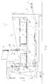
- FIG. 1 shows a device 1 carried by a machine frame 10 for forming a stack 2 of printed sheets 3 strung together, also referred to as bar delivery, in which the printed sheets 3 are folded from the right side via conveyor belts 4 to 8 initially by a pressing device 9, consisting of two superimposed ones Press rolls formed to be guided to press the folds.
- the printing sheets 3 are transported in a shingled formation, in which the following printing sheet 3 partially rests on the preceding one (see scale position on conveyor belt 6).
- Such a scale formation can be adopted, for example, on the delivery of a printing press.
- the printed sheets 3, in the still scaled state reach an approximately vertically rising conveyor section 11, which is formed by the conveyor belts 12, 13.
- the printed sheets 3 are clamped between the conveyor belts 12, 13, which rotate together around the rollers 14, 15.
- the conveyor belt 12 runs around the counter roller 16 via further rollers about the axis of the lower press roller of the pressing device 9 to the roller 14;
- Conveyor belt 13 runs around the rollers 14, 15 and is deflected from the conveyor path of the printed sheets 3 after leaving the roller 15.
- Such conveyors are known, for example, from CH-A-663 397 and the printed sheets 3 could, as disclosed in EP-A-0 623 542, be fed in oversized.
- the printed sheets 3 are delivered to a similar conveyor 18 directed perpendicularly against a stacking support 17.
- the operation of the conveyor channel 21 is also described in the above-mentioned publications.
- the stack supports 17, 22 provided are attached to two traction elements formed from rotating pairs of chains, one of which is designated by 24.
- a controllable drive motor (not shown) is assigned to each traction element, so that, for example, a reduced speed of the stack supports 17, 22 can be driven during the stack formation.
- the stack supports 17, 22 are formed from transversely running strips 23 and are supported on guide rails with respect to the upper runs of the traction elements.
- the traction elements run around deflection rollers 25, 26 which, viewed in the direction of stack formation, are arranged before the infeed of the shingled stream onto the stack supports and behind a downstream stack press 27.
- the stack supports 17, 22 have support elements 28, 29 arranged at the ends in pairs, between which a stack 2 is in each case formed and transported.
- the rear support elements 29 of a stack support 17, 22 abut the front support elements 28 of a subsequent stack support 17, 22 and thus form a stack separation when passing through the conveying channel 21.
- the completed stack 2 passes after it has passed has set off from the subsequent stack 2 at an increased speed, a controllable insertion device 30, with which the end edges of the stack 2, which protect against damage, are inserted between the support elements 28, 29 of a stack support 17, 22 and the stack 2.
- the insertion device 30 consists of two parallel holding plates 32, 33, spaced apart from one another, forming an intermediate space for at least one end plate 31. These have slit-like passage openings 38 at the lower end through which the support elements 28, 29 can pass for pressing the stacked printed sheets 3 together , 2a to 2f, the end plate insertion during the stacking process is described.
- the stack 2 which has formed has reached a certain length and, with the front end, which is formed by a pair of support elements 28, approaches the ready-to-insert device 30, to which an end plate 31 has previously been fed from a magazine 34 arranged above it. Due to the selected stack length or the stack speed, the insertion device 30 has covered a longer or shorter path since the end plate 31 was received until it has reached the illustrated position. Of course, at the expense of the cycle time and possibly the quality, the insertion device 30 could be operated on shorter paths or at a standstill, or the end plates could be inserted. In the situation shown, the insertion device 30 is close to inserting the end plate 31 between the front of the stack 2 and the support elements 28.
- the end plate 31 is caught at a height above the support elements 28 in the insertion device 30, for which purpose a retaining device 35 is provided.
- a guide arrangement designated 36 is set up, which can be seen in more detail in FIG. 3.
- the height adjustment of the holding plates 32, 33 takes place via a pneumatic actuating device 37 which can be seen in FIG. 3.
- the specified means allow the insertion device 30 to be moved along the rationally shortest route to underpass the end plates 31 and to reset them.
- An insertion device 30, with which two end plates 31 can be received, could be a return path to the stacking support 17, 22 or. saved to magazine 34.
- the insertion device 30 with a space for one or two end plates 31 or for two end plates 31 in separate spaces.
- 2b the end plate 31 loaded in the insertion device 30 is deflected and, by pushing back the front end of the stack 2 through the holding plate 32 of the insertion device 30, has been placed behind the support elements 28 in a position in which it is initially loosely in that by the holding plates 32, 33 formed space sits.
- 2c shows the further step, where the insertion device 30 is lifted and the end plate 31 is clamped between the stack and the support elements 28 by expansion of the stack 2.
- the insertion device 30 has already received another end plate 31, which is provided for the rear end of the stack 2. It would be possible to insert the insert device 30 with two spaces.
- the stack 2 has reached approximately the insertion position with its rear end, which is determined by support elements 29; likewise the insertion device 30. Now the insertion device 30 is driven faster than the stack 2 in the direction of travel, so that the position according to FIG. 2e is reached immediately. In this position, the rear end of the stack is advanced such that there is a gap between it and the subsequent support element 29, into which the end plate 31 is inserted from top to bottom or from the retention position in the insertion device 30. 2e, the restraint device 35 is already out of operation and the end plate 31 stands on the stacking support 17.
- the insertion device 30 is from the rear End of stack of stack 2 removed and already an end plate 31 for the next stack 2, which is at a certain distance follows, picked up from magazine 34.
- the Retaining device 35 in the space between the holding plates 32, 33 switched and holds the end plate 31 in one raised position above the passage openings so that the front support members 28 of the new stack 2 for insertion drive through the end plate 31 through the holding plates 32, 33 can, as shown in Figs. 2a and 2b.
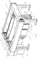
- FIG. 3 an insertion device 30 is illustrated in more detail than in Figs. 1 and 2a to 2f.
- a frame 39 which is advantageously supported on the machine frame 10 of the device 1 and can be connected to the latter, consists of four supports 40, at the upper end of which a frame 41 made of two cross members 42 and longitudinal members 43 is fastened.
- the guide arrangement 36 has a rod 44 which extends parallel to the conveying direction F and on which a support 45 which carries the holding plates 32, 33 of the insertion device 30 is mounted so as to be longitudinally displaceable.
- the support 45 is in each case coupled by a connecting element 47, for example a clamping device, to a drive belt 46 which is guided around deflecting rollers 48 arranged one above the other in pairs on the frame 41 and opposite on a drive roller (only bearing 49 visible).
- the drive rollers are fastened to a shaft 50 which is coupled to a gear 51 of a drive unit 52.
- the supports 45 are mutually supported by lateral strips 53 against lateral tilting.
- the connected holding plates 32, 33 form an intermediate space for the end plate 31 and have passage openings 38 for the pairs of support elements 28, 29 provided at the ends of the stack supports 17, 22.
- the holding plates 32, 33 are each guided vertically displaceably at the lateral ends in a guide 54 fastened to the support 45, the upper position being assigned to the receptacle of an end plate 31 from the magazine 34; and in the lower position, the holding plates 32, 33 are positioned for inserting the end plate 31 at the stack ends.
- the actuation of the holding plates 32, 33 is achieved by means of pneumatic cylinders 55 arranged on both sides, which are fastened to the supports 45 and act with a piston rod 56 on a holder 57 fastened to the holding plates 32, 33.
- the retaining device 35 is located on the holding plate 33 and has a pawl 58 which can be pivoted in the intermediate space by means of a piston-cylinder unit 59, and can be set into an operating and an out-of-operation position.
Abstract
Description
Die Erfindung betrifft eine Einrichtung zur Bildung eines Stapels aneinandergereihter Druckbogen, bestehend aus einer die Druckbogen in einer Schuppenformation senkrecht einer Stapelauflage zuführenden Fördervorrichtung und einer der zur Stapelbildung vorgesehenen Stapelauflage zugeordneten, die Länge eines Stapels durch endseitig zwischen Stützelementen und Stapel zustellbare Endplatten bildende, steuerbare Einschubvorrichtung.The invention relates to a device for forming a stack lined up printed sheet consisting of a die Printing sheets in a scale formation perpendicular to a stacking support feeding conveyor and one of the stacks provided stacking pad assigned to the length of a stack by the end between support elements and stack controllable insertion device forming deliverable end plates.
Auf diese Art hergestellte Stapel werden im Fachjargon auch Stangen und die dazu benutzte Einrichtung als Stangenausleger bezeichnet. Die gepressten und umreiften Stangen werden üblicherweise vorerst zwischengelagert und gelangen sodann zur Vereinzelung der Druckbogen zu einem Anleger, der zur Beschickung einer Verarbeitungsstrecke mit den Druckbogen vorgesehen ist.Stacks made in this way are also used in technical jargon Poles and the equipment used as a pole boom designated. The pressed and strapped bars are usually temporarily stored and then arrive at Separation of the printed sheets to a feeder for loading a processing line provided with the printed sheets is.
Eine Einrichtung der eingangs beschriebenen Art ist in der CH - A - 663 397 offenbart. Die vornehmlich zum Schutz gegen Beschädigungen der endseitigen Druckbogen von Hand einzulegenden Endplatten verlangen eine hundertprozentige Präsenzzeit einer Bedienungsperson, die sich in hohem Mass auf ein korrektes Einstecken der Endplatten zwischen dem gebildeten Stapel und die diesen endseitig stützenden Stützelemente konzentriert. Eine Ueberwachung des Papierflusses im Zuführbereich und des Abpressens der Stapel vor der Auslage wird durch die für den manuellen Einschub der Endplatten erforderlichen Arbeitszeit erheblich eingeschränkt und auch das Bereitstellen der Endplatten lässt sich mit einer Bedienungsperson während dem Betrieb der Einrichtung kaum bewerkstelligen.A device of the type described above is in CH - A - 663 397. The primarily to protect against damage the printed sheet to be inserted by hand End plates require a one hundred percent presence time Operator who relies heavily on a correct Insert the end plates between the stack and which concentrates these end support elements. Monitoring the paper flow in the feed area and the Pressing the stack in front of the delivery is done by the for the manual insertion of the end plates required working time considerably restricted and also the provision of the end plates can be used with an operator during operation the facility hardly manage.
Deshalb stellt sich an die vorliegende Erfindung die Aufgabe, die Beschickung der Endplatten an den Stapelenden zu automatisieren, um der Bedienungsperson die Arbeit erleichtern und ausreichend Zeit für die Ueberwachung des ablaufenden Sammelprozesses sowie der Bereitstellung der Endplatten einräumen zu können.Therefore, the object of the present invention is automate the loading of the end plates at the stack ends, to make the operator's job easier and sufficient time to monitor the ongoing collection process as well as the provision of the end plates can.
Erfindungsgemäss wird diese Aufgabe dadurch gelöst, dass die Einschubvorrichtung durch eine dem vorderen und hintern Stapelende zugeordnete, mit Durchtrittsöffnungen für die passierenden Stützelemente versehenen, senkrecht gegen die Stapelauflage antreibbaren, die Endplatten an den Stapelenden einsetzenden Einsteckvorrichtung ausgebildet ist, die wenigstens einen mit einer Endplatte beschickbaren Zwischenraum aufweist. Dadurch werden die erwähnten Nachteile weitestgehend behoben.According to the invention, this object is achieved in that the Insert device through one of the front and rear end of the stack assigned, with passage openings for the passing Support elements provided, vertically against the stack support drivable, inserting the end plates at the stack ends Insert device is formed, the at least one having a gap that can be filled with an end plate. This largely eliminates the disadvantages mentioned.
Vorzugsweise ist die Einsteckvorrichtung durch wenigstens zwei parallele, eine Endplatte in einem Zwischenraum aufnehmende Halteplatten gebildet. The insertion device is preferably by at least two parallel, receiving an end plate in a space Holding plates formed.
Die Einschubvorrichtung kann zwei, jeweils einer Endplatte eines Stapels zugeordnete Zwischenräume aufweisen, sodass weniger Bewegungen der Einschubvorrichtung erforderlich sind und für den Enplatteneinschub mehr Zeit verfügbar ist.The insertion device can have two, one end plate each Stack associated gaps, so less Movements of the insertion device are required and more time is available for inserting the plate.
Es ist vorteilhaft, wenn die Einschubvorrichtung in einer gegenüber der Stapelauflage rechtwinklig versetzten Position mit Endplatten beschickbar ist, wodurch die Bereitstellung der Endplatten vereinfacht wird.It is advantageous if the insertion device is in an opposite position position of the stacking support at a right angle Endplates is feedable, thereby providing the End plates is simplified.
Es wird sich als zweckmässig erweisen, wenn die Einschubvorrichtung in einer gegenüber der Stapelauflage zurückversetzten Position mit Endplatten beschickbar ist, wodurch ein leicht zugänglicher Bereitstellungsraum entstehen kann.It will prove useful if the insertion device in a set back compared to the stack support Position can be loaded with end plates, which makes it easy accessible staging area can arise.
Die Anpassung der Endplattenzuführung an den kontinuierlichen Stapelbildungsvorgang kann optimiert werden, wenn die Einschubvorrichtung entlang der Stapelbildungsrichtung hin und her verfahrbar ist.The adaptation of the end plate feed to the continuous Stacking process can be optimized if the insertion device along the stack formation direction and can be moved here.
Vorzugsweise ist die Einschubvorrichtung oberhalb der horizontal ausgerichteten Stapelauflage angeordnet, so dass die Endplatten durch ihr Eigengewicht oder mittels Ueberführungsvorrichtung in die Einschubvorrichtung fallen bzw. versetzt werden können.The insertion device is preferably above the horizontal aligned stacking pad so that the end plates by their own weight or by means of a transfer device fall into the insertion device or be moved can.
Zweckmässig sind die Halteplatten in einem ortsfest angeordneten Gerüst parallel zur Stapelbildungsrichtung geführt, sodass ein einfacher Bewegungsantrieb verwendbar ist. The holding plates are expediently arranged in a stationary manner Scaffold guided parallel to the stack formation direction so that a simple motion drive can be used.
Um die Endplatten auf kürzestem Weg zwischen Stapel und Stützelemente in die Betriebslage versetzen zu können, ist es günstig, wenn wenigstens eine der Halteplatten mit eine oberhalb der für die durchlaufenden Stützelemente vorgesehenen Durchtrittsöffnungen in den Zwischenraum schaltbare Zurückhaltevorrichtung ausgebildet ist.Around the end plates in the shortest way between the stack and the support elements to be able to put it in the operating position, it is favorable if at least one of the holding plates with one above the passage openings provided for the continuous support elements retention device which can be switched into the intermediate space is trained.
Es erweist sich als geeignet, wenn die zur Beschickung der Endplatten vorgesehene Position als Magazin zur Stapelung und Ausgabe von Endplatten ausgebildet ist.It turns out to be suitable if the for loading the End plates provided position as a magazine for stacking and Output of end plates is formed.
Anschliessend wird die Erfindung unter Bezugsnahme auf die Zeichnung, auf die bezüglich aller in der Beschreibung nicht näher erwähnten Einzelheiten verwiesen wird, anhand eines Ausführungsbeispiels erläutert. In der Zeichnung zeigen:
- Fig. 1
- eine schematische Seitenansicht der erfindungsgemässen Einrichtung,
- Fig. 2a - 2f
- eine schematische Darstellung des Endplatteneinschubs bei der Stapelbildung und
- Fig. 3
- eine räumliche Darstellung einer Einschubvorrichtung für Endplatten.
- Fig. 1
- 2 shows a schematic side view of the device according to the invention,
- 2a-2f
- is a schematic representation of the end plate insert during stacking and
- Fig. 3
- a spatial representation of an insertion device for end plates.
Die Fig. 1 zeigt eine von einem Maschinengestell 10 getragene
Einrichtung 1 zur Bildung eines Stapels 2 aneinandergereihter
Druckbogen 3, auch Stangenausleger bezeichnet, bei der die
Druckbogen 3 von der rechten Seite über Förderbänder 4 bis 8
falzvoran vorerst durch eine Pressvorrichtung 9, aus zwei
übereinanderliegenden Presswalzen gebildet, zum Abpressen der
Falze geführt werden. Dabei werden die Druckbogen 3 in einer
geschuppten Formation transportiert, in der der jeweils nachfolgende
Druckbogen 3 auf dem vorauslaufenden teilweise aufliegt
(siehe Schuppenlage auf Förderband 6). Eine solche
Schuppenformation kann beispielsweise an der Auslage einer
Druckmaschine übernommen werden. Nach der Pressvorrichtung 9
erreichen die Druckbogen 3 im weiterhin geschuppten Zustand
einen etwa senkrecht ansteigenden Förderabschnitt 11, der
durch die Förderbänder 12, 13 gebildet wird. Auf dem Förderabschnitt
11 sind die Druckbogen 3 zwischen den Förderbändern
12, 13 eingespannt, die gemeinsam um die Rollen 14, 15 umlaufen.
Förderband 12 läuft nach der Rolle 15 um die Gegenrolle
16 über weitere Rollen um die Achse der unteren Presswalze der
Pressvorrichtung 9 an die Rolle 14 zurück; Förderband 13 läuft
um die Rollen 14, 15 um und wird nach Verlassen der Rolle 15
von der Förderbahn der Druckbogen 3 abgelenkt. Derartige Fördereinrichtungen
sind beispielsweise aus der CH - A - 663 397
bekannt und die Druckbogen 3 könnten wie in der EP - A - 0 623
542 offenbart oberschlächtig zugeführt werden. Nach einer 180°
Umlenkung am Förderende des Förderabschnittes 11 werden die
Druckbogen 3 an einen gleichartigen, senkrecht gegen eine Stapelauflage
17 gerichteten Förderer 18 abgegeben. Dieser weist
einen aus zwei parallelen Trums zweier Förderbänder 19, 20 gebildeten
Förderkanal 21 auf, der über dem sich bildenden Stapel
2 endet und durch den letzten auf der Stapelauflage 17, 22
eintreffenden Druckbogen 3 fortgesetzt wird. Die Funktionsweise
des Förderkanals 21 ist ebenfalls in den oben genannten
Druckschriften beschrieben.
Die vorgesehenen Stapelauflagen 17, 22 sind an zwei aus umlaufenden
Kettenpaaren gebildeten Zugorganen befestigt, von denen
eines mit 24 bezeichnet ist. Jedem Zugorgan ist ein steuerbarer
Antriebsmotor (nicht ersichtlich) zugeordnet, sodass beispielsweise
während der Stapelbildung eine reduzierte Geschwindigkeit
der Stapelauflagen 17, 22 gefahren werden kann.
Die Stapelauflagen 17, 22 sind aus querverlaufenden aneinandergereihten
Leisten 23 gebildet und bezüglich der oberen
Trums der Zugorgane auf Führungsschienen abgestützt.
Die Zugorgane laufen um Umlenkrollen 25, 26, die in Stapelbildungsrichtung
betrachtet vor dem Einlauf des Schuppenstromes
auf die Stapelauflagen und hinter einer nachgeschalteten Stapelpresse
27 angeordnet sind. Die Stapelauflagen 17, 22 weisen
an den paarweise Enden angeordnete Stützelemente 28, 29 auf,
zwischen denen ein Stapel 2 jeweils gebildet und transportiert
wird. Bei Beginn einer Stapelbildung liegen die hinteren
Stützelemente 29 einer Stapelauflage 17, 22 an den vorderen
Stützelementen 28 einer nachfolgenden Stapelauflage 17, 22 an
und bilden so eine Stapeltrennung beim Durchlaufen des Förderkanals
21. Auf dem weiteren Weg passiert der vollendete Stapel
2, nachdem er sich von dem nachfolgenden Stapel 2 mit erhöhter
Geschwindigkeit abgesetzt hat, eine steuerbare Einschubvorrichtung
30, mit welcher dem zwischen den Stützelementen 28,
29 einer Stapelauflage 17, 22 und dem Stapel 2 die Endkanten
des Stapels 2 gegen Beschädigungen schützende Endplatten 31
eingeschoben werden. Die Einschubvorrichtung 30 besteht aus
zwei parallelen, voneinander, einen Zwischenraum für wenigstens
eine Endplatte 31 bildend, beabstandete Halteplatten 32,
33. Diese weisen am unteren Ende schlitzartige Durchtrittsöffnungen
38 auf, durch die die Stützelemente 28, 29 zum Zusammenpressen
der gestapelten Druckbogen 3 durchtreten können.
Zu den Fig. 2a bis 2f wird anschliessend der Endplatteneinschub
bei dem Stapelbildungsvorgang beschrieben. In Fig. 2a
hat der sich bildende Stapel 2 eine gewisse Länge erreicht und
nähert sich mit dem vorderen Ende, das durch ein Stützelementepaar
28 gebildet wird, der bereitstehenden Einschubvorrichtung
30, welcher zuvor eine Endplatte 31 aus einem darüber angeordneten
Magazin 34 zugeführt wurde. Aufgrund der gewählten
Stapellänge oder der Stapelgeschwindigkeit legt die Einschubvorrichtung
30 seit der Aufnahme der Endplatte 31 einen längeren
oder kürzeren Weg zurück, bis sie die veranschaulichte Position
erreicht hat. Selbstverständlich könnte auf Kosten der
Zykluszeit und allenfalls der Qualität die Einschubvorrichtung
30 auf kürzeren Wegen oder im Stillstand betrieben bzw. die
Endplatten eingesteckt werden. In der dargestellten Situation
befindet sich die Einschubvorrichtung 30 kurz davor, die Endplatte
31 zwischen Vorderseite des Stapels 2 und Stützelemente
28 einzusetzen. Hierzu ist die Endplatte 31 in einer Höhe über
den Stützelementen 28 in der Einschubvorrichtung 30 gefangen,
wozu eine Rückhaltevorrichtung 35 vorgesehen ist. Zur Hin- und
Herbewegung der Einschubvorrichtung 30 in horizontaler Richtung
bzw. parallel zur Stapelbildungsrichtung ist eine mit 36
bezeichnete Führungsanordnung eingerichtet, die in Fig. 3 ausführlicher
erkennbar ist. Die Höhenverstellung der Halteplatten
32, 33 erfolgt über eine pneumatische Betätigungsvorrichtung
37 die in der Fig. 3 ersichtlich ist. Die angegebenen
Mittel erlauben es, dass die Einschubvorrichtung 30 auf dem
rationell kürzesten Weg zur Unterführung der Endplatten 31 und
zur Rückstellung verfahren werden kann.
Eine Einschubvorrichtung 30, mit der zwei Endplatten 31 aufgenommen
werden können, könnte ein Hin- und Rückweg zur Stapelauflage
17, 22 resp. zum Magazin 34 eingespart werden. Es wäre
somit möglich, die Einschubvorrichtung 30 mit einem Zwischenraum
für eine oder zwei Endplatten 31 oder für zwei Endplatten
31 in getrennten Zwischenräumen auszubilden.
In Fig. 2b ist die in der Einschubvorrichtung 30 geladene Endplatte
31 abgerenkt und durch Zurückdrängen des vorderen Endes
des Stapels 2 durch die Halteplatte 32 der Einschubvorrichtung
30 hinter die Stützelemente 28 in eine Lage versetzt worden,
in der sie vorerst lose in dem durch die Halteplatten 32, 33
gebildeten Zwischenraum sitzt.
Fig. 2c zeigt den weiteren Schritt, wo die Einschubvorrichtung
30 ausgehoben und die Endplatte 31 durch Expansion des Stapels
2 zwischen diesem und den Stützelementen 28 eingeklemmt ist.
Die Einschubvorrichtung 30 hat bereits eine andere Endplatte
31 aufgenommen, die für das rückwärtige Ende des Stapels 2
vorgesehen ist. Es bestünde die Möglichkeit, die Einschubvorrichtung
30 mit zwei Zwischenräumen resp. so auszubilden, dass
sie zwei Endplatten 31 aufnehmen und diese nacheinander an den
Enden eines Stapels 2 platzieren kann. Gemäss Fig. 2d hat der
Stapel 2 mit seinem hinteren Ende, das durch Stützelemente 29
bestimmt ist, etwa die Einschubposition erreicht; ebenso die
Einschubvorrichtung 30.
Nun wird die Einschubvorrichtung 30 schneller als der Stapel 2
in Fortbewegungsrichtung angetrieben, so dass umgehend die Position
gemäss Fig. 2e erreicht wird. In dieser Position ist
das hintere Stapelende vorgeschoben, derart, dass zwischen
diesem und dem nachfolgenden Stützelement 29 eine Lücke entsteht,
in die die Endplatte 31 von oben nach unten bzw. aus
der Rückhalteposition in der Einschubvorrichtung 30 eingesetzt
wird. In Fig. 2e ist Rückhaltevorrichtung 35 bereits ausser
Betrieb und die Endplatte 31 steht auf der Stapelauflage 17
auf. 1 shows a device 1 carried by a
The stack supports 17, 22 provided are attached to two traction elements formed from rotating pairs of chains, one of which is designated by 24. A controllable drive motor (not shown) is assigned to each traction element, so that, for example, a reduced speed of the stack supports 17, 22 can be driven during the stack formation. The stack supports 17, 22 are formed from transversely running
The traction elements run around
2a to 2f, the end plate insertion during the stacking process is described. 2a, the
An
2b, the
2c shows the further step, where the
Now the
In Fig. 2f hat sich die Einschubvorrichtung 30 vom hinteren
Stapelende des Stapels 2 entfernt und auch schon eine Endplatte
31 für den nächsten Stapel 2, der in einem bestimmten Abstand
folgt, aus dem Magazin 34 abgeholt. Hierbei ist die
Rückhaltevorrichtung 35 in den Zwischenraum zwischen den Halteplatten
32, 33 geschaltet und hält die Endplatte 31 in einer
angehobenen Position über den Durchtrittsöffnungen, so dass
die vorderen Stützelemente 28 des neuen Stapels 2 für das Einsetzen
der Endplatte 31 durch die Halteplatten 32, 33 durchfahren
können, wie in den Fig. 2a und 2b dargestellt.In Fig. 2f, the
In Fig. 3 ist eine Einschubvorrichtung 30 detaillierter als in
den Fig. 1 und 2a bis 2f veranschaulicht. Ein vorteilhaft auf
dem Maschinengestell 10 der Einrichtung 1 abstütz- und mit
letzterer verbindbares Gerüst 39, besteht aus vier Stützen 40,
an deren oberem Ende ein Rahmen 41 aus jeweils zwei Quer- 42
und Längsträgern 43 befestigt ist. An den aus einem C-Profil
gebildeten Längsträgern 43 ist eine Führungsanordnung 36 befestigt,
an der die Halteplatten 32, 33 antreibbar geführt
bzw. aufgehängt sind.
Die Führungsanordnung 36 weist eine sich parallel zur Förderrichtung
F erstreckende Stange 44 auf, an der jeweils ein die
Halteplatten 32, 33 der Einschubvorrichtung 30 tragender Support
45 längsverschiebbar gelagert ist. Der Support 45 ist jeweils
durch ein Verbindungselement 47, beispielsweise einer
Klemmvorrichtung mit einem Antriebsriemen 46 gekoppelt, der um
einseitig des Rahmens 41 paarweise übereinander angeordneten
Umlenkrollen 48 und gegenüberliegend auf einer Antriebsrolle
(nur Lager 49 ersichtlich) geführt ist. Die Antriebsrollen
sind an einer Welle 50 befestigt, die mit einem Getriebe 51
einer Antriebseinheit 52 gekuppelt ist. Die Supports 45 sind
durch Querleisten 53 gegen seitliches Kippen gegenseitig abgestützt.
Die verbundenen Halteplatten 32, 33 bilden einen Zwischenraum
für die Endplatte 31 und weisen Durchtrittsöffnungen
38 für die an den Enden der Stapelauflagen 17, 22 vorgesehenen
Stützelementenpaare 28, 29 auf.
Die Halteplatten 32, 33 sind an den seitlichen Enden jeweils
in einer an dem Support 45 befestigten Führung 54 vertikal
versetzbar geführt, wobei die obere Stellung der Aufnahme einer
Endplatte 31 aus dem Magazin 34 zugeordnet; und in der unteren
Stellung sind die Halteplatten 32, 33 zum Einsetzen der
Endplatte 31 an den Stapelenden positioniert. Die Betätigung
der Halteplatten 32, 33 wird durch beidseits angeordnete Pneumatikzylinder
55 erreicht, die an den Supports 45 befestigt
sind und mit einer Kolbenstange 56 auf einen an den Halteplatten
32, 33 befestigten Halter 57 einwirken.
Die Rückhaltevorrichtung 35 befindet sich an der Halteplatte
33 und weist eine Klinke 58 auf, die mittels einer Kolbenzylindereinheit
59 im Zwischenraum schwenkbar, in eine Betriebs-
und eine Ausserbetriebsstellung versetzbar ist.In Fig. 3, an
The
The holding
The retaining
Claims (10)
Priority Applications (4)
| Application Number | Priority Date | Filing Date | Title |
|---|---|---|---|
| DE50007081T DE50007081D1 (en) | 2000-10-20 | 2000-10-20 | Device for forming a stack of printed sheets lined up |
| EP00810974A EP1199275B1 (en) | 2000-10-20 | 2000-10-20 | Device for making a stack of printed sheets arranged side by side |
| JP2001271688A JP4762455B2 (en) | 2000-10-20 | 2001-09-07 | Apparatus for the formation of a stack of parallel printed sheets |
| US09/970,500 US6568672B2 (en) | 2000-10-20 | 2001-10-04 | Device for forming a stack of successively arranged printed sheets |
Applications Claiming Priority (1)
| Application Number | Priority Date | Filing Date | Title |
|---|---|---|---|
| EP00810974A EP1199275B1 (en) | 2000-10-20 | 2000-10-20 | Device for making a stack of printed sheets arranged side by side |
Publications (2)
| Publication Number | Publication Date |
|---|---|
| EP1199275A1 true EP1199275A1 (en) | 2002-04-24 |
| EP1199275B1 EP1199275B1 (en) | 2004-07-14 |
Family
ID=8174983
Family Applications (1)
| Application Number | Title | Priority Date | Filing Date |
|---|---|---|---|
| EP00810974A Expired - Lifetime EP1199275B1 (en) | 2000-10-20 | 2000-10-20 | Device for making a stack of printed sheets arranged side by side |
Country Status (4)
| Country | Link |
|---|---|
| US (1) | US6568672B2 (en) |
| EP (1) | EP1199275B1 (en) |
| JP (1) | JP4762455B2 (en) |
| DE (1) | DE50007081D1 (en) |
Cited By (3)
| Publication number | Priority date | Publication date | Assignee | Title |
|---|---|---|---|---|
| FR2869598A1 (en) * | 2004-05-03 | 2005-11-04 | Recmi Ind Sa | Board distribution and installation device for horizontal stacking device, has two arms displaced in parallel to stacking table synchronously to install front and rear boards at front and back of new and formed cartridges, respectively |
| US7168910B2 (en) | 2002-07-02 | 2007-01-30 | Muller Martini Holding Ag | Device for transporting a horizontal stack positioned on a support and formed in a gathering machine with upright, lined-up signatures |
| EP1816098A1 (en) | 2006-02-02 | 2007-08-08 | Müller Martini Holding AG | Method and device for forming stacks |
Families Citing this family (2)
| Publication number | Priority date | Publication date | Assignee | Title |
|---|---|---|---|---|
| DE10048827C1 (en) * | 2000-09-29 | 2001-09-13 | Siemens Ag | Postal article receiver for postal sorting plant has sending transporter track with short fixed first sector and long second sector on chassis |
| DE102004062648B4 (en) * | 2004-12-21 | 2006-09-07 | Kronotec Ag | Device for inserting springs in the front and / or long sides of technical wood products |
Citations (4)
| Publication number | Priority date | Publication date | Assignee | Title |
|---|---|---|---|---|
| US4641489A (en) * | 1984-09-28 | 1987-02-10 | World Color Press, Inc. | Machine for handling signatures |
| CH663397A5 (en) * | 1984-05-11 | 1987-12-15 | Grapha Holding Ag | STACKING DEVICE FOR PRINTED SHEET. |
| EP0340494A2 (en) * | 1988-05-06 | 1989-11-08 | Baldwin Technology Corporation | Handling signatures |
| EP0623542A1 (en) * | 1993-05-07 | 1994-11-09 | Grapha-Holding Ag | Device for forming a stack of printed sheets, where these are piled on the edge |
Family Cites Families (4)
| Publication number | Priority date | Publication date | Assignee | Title |
|---|---|---|---|---|
| CH583653A5 (en) * | 1974-10-07 | 1977-01-14 | Ferag Ag | |
| US4172531A (en) * | 1975-12-29 | 1979-10-30 | Grapha-Holding Ag | Apparatus for transforming a stream of overlapping paper sheets into a staple of sheets |
| IT1175477B (en) * | 1984-04-09 | 1987-07-01 | Sitma | FEEDER OF SIGNING SHEETS AND SIMILAR PRODUCTS FOR FEEDERS OF MACHINES PACKAGING MACHINES FOR BINDING AND SIMILAR |
| US4934687A (en) * | 1988-01-11 | 1990-06-19 | Galpin Research, Limited Partnership | High speed stream fed stacker method and system for printed products |
-
2000
- 2000-10-20 DE DE50007081T patent/DE50007081D1/en not_active Expired - Lifetime
- 2000-10-20 EP EP00810974A patent/EP1199275B1/en not_active Expired - Lifetime
-
2001
- 2001-09-07 JP JP2001271688A patent/JP4762455B2/en not_active Expired - Fee Related
- 2001-10-04 US US09/970,500 patent/US6568672B2/en not_active Expired - Lifetime
Patent Citations (4)
| Publication number | Priority date | Publication date | Assignee | Title |
|---|---|---|---|---|
| CH663397A5 (en) * | 1984-05-11 | 1987-12-15 | Grapha Holding Ag | STACKING DEVICE FOR PRINTED SHEET. |
| US4641489A (en) * | 1984-09-28 | 1987-02-10 | World Color Press, Inc. | Machine for handling signatures |
| EP0340494A2 (en) * | 1988-05-06 | 1989-11-08 | Baldwin Technology Corporation | Handling signatures |
| EP0623542A1 (en) * | 1993-05-07 | 1994-11-09 | Grapha-Holding Ag | Device for forming a stack of printed sheets, where these are piled on the edge |
Cited By (4)
| Publication number | Priority date | Publication date | Assignee | Title |
|---|---|---|---|---|
| US7168910B2 (en) | 2002-07-02 | 2007-01-30 | Muller Martini Holding Ag | Device for transporting a horizontal stack positioned on a support and formed in a gathering machine with upright, lined-up signatures |
| FR2869598A1 (en) * | 2004-05-03 | 2005-11-04 | Recmi Ind Sa | Board distribution and installation device for horizontal stacking device, has two arms displaced in parallel to stacking table synchronously to install front and rear boards at front and back of new and formed cartridges, respectively |
| EP1816098A1 (en) | 2006-02-02 | 2007-08-08 | Müller Martini Holding AG | Method and device for forming stacks |
| US7862020B2 (en) | 2006-02-02 | 2011-01-04 | Mueller Martini Holding Ag | Method for forming stacks from upright positioned, successively lined up signatures and arrangement for realizing the method |
Also Published As
| Publication number | Publication date |
|---|---|
| US6568672B2 (en) | 2003-05-27 |
| JP2002145508A (en) | 2002-05-22 |
| EP1199275B1 (en) | 2004-07-14 |
| JP4762455B2 (en) | 2011-08-31 |
| US20020047236A1 (en) | 2002-04-25 |
| DE50007081D1 (en) | 2004-08-19 |
Similar Documents
| Publication | Publication Date | Title |
|---|---|---|
| EP0623542B1 (en) | Device for forming a stack of printed sheets, where these are piled on the edge | |
| EP0089407B1 (en) | Device for dividing a stream of printed products | |
| DE60113580T2 (en) | Cutting machine for a variety of kitchen and / or toilet paper rolls | |
| DE2716806A1 (en) | DEVICE FOR STACKING FLAT MATERIAL PIECES | |
| DE19849859A1 (en) | Device for forming and removing stacks of sheets | |
| DE2508745C2 (en) | Device for accumulating individually by means of a transport device fed paper sheets into stacks and for further transporting these stacks | |
| EP1350750B1 (en) | Method and device for forming piles of continuously delivered, flat ojects | |
| DE102005002532A1 (en) | Device and method for automated and simultaneous provision and change of at least two rolls of paper webs or the like for a downstream format cutter | |
| EP1405809A1 (en) | Device for forming parcels of stacked products | |
| DE19533086A1 (en) | Method and device for stacking flat products, in particular printed products | |
| DE3910041A1 (en) | BOW FEEDER FOR SUPPLYING A BOW CURRENT ARRAY OF SINGLE BOWS TO A BOW-PROCESSING MACHINE | |
| EP1107865A1 (en) | Device for producing and withdrawing stacks of plastic bags, especially bags for automatic machines | |
| EP1199275B1 (en) | Device for making a stack of printed sheets arranged side by side | |
| DE1436064C3 (en) | Device for gathering folded sheets into a book block | |
| DE1153383B (en) | Device for depositing sheet-like products on a rotary printing press | |
| DE1561141B2 (en) | DEVICE FOR INSERTING INSERTS INTO FOLDED PRINT PRODUCTS | |
| DE102008048831A1 (en) | Conveying device for packaging machine, has buffer conveyor, on which containers are conveyed, and collecting conveyor, through which containers are brought in predetermined distance to each other | |
| EP0406658A1 (en) | Device for temporary storing products | |
| EP1245518B1 (en) | Pile former | |
| EP0386580A1 (en) | Method and apparatus for removing flocks from fiber bales | |
| EP0603354B1 (en) | Feed device for an insetting machine for printed products | |
| DE4441453A1 (en) | Device for collecting sheets of paper in stacks | |
| DE3926966A1 (en) | Device for forming gaps in overlapping material flow - has stationary guide rollers and different speeds for outlet conveyor | |
| DE102009022249B4 (en) | Transfer device for transferring a stack formed by a plurality of sheet layers | |
| DE3519841A1 (en) | Device for glueing flat textile pieces |
Legal Events
| Date | Code | Title | Description |
|---|---|---|---|
| PUAI | Public reference made under article 153(3) epc to a published international application that has entered the european phase |
Free format text: ORIGINAL CODE: 0009012 |
|
| AK | Designated contracting states |
Kind code of ref document: A1 Designated state(s): CH DE FR GB IT LI Kind code of ref document: A1 Designated state(s): AT BE CH CY DE DK ES FI FR GB GR IE IT LI LU MC NL PT SE |
|
| AX | Request for extension of the european patent |
Free format text: AL;LT;LV;MK;RO;SI |
|
| 17P | Request for examination filed |
Effective date: 20020730 |
|
| AKX | Designation fees paid |
Free format text: CH DE FR GB IT LI |
|
| GRAP | Despatch of communication of intention to grant a patent |
Free format text: ORIGINAL CODE: EPIDOSNIGR1 |
|
| GRAS | Grant fee paid |
Free format text: ORIGINAL CODE: EPIDOSNIGR3 |
|
| GRAA | (expected) grant |
Free format text: ORIGINAL CODE: 0009210 |
|
| AK | Designated contracting states |
Kind code of ref document: B1 Designated state(s): CH DE FR GB IT LI |
|
| REG | Reference to a national code |
Ref country code: GB Ref legal event code: FG4D Free format text: NOT ENGLISH |
|
| REG | Reference to a national code |
Ref country code: CH Ref legal event code: EP |
|
| REF | Corresponds to: |
Ref document number: 50007081 Country of ref document: DE Date of ref document: 20040819 Kind code of ref document: P |
|
| REG | Reference to a national code |
Ref country code: IE Ref legal event code: FG4D Free format text: GERMAN |
|
| GBT | Gb: translation of ep patent filed (gb section 77(6)(a)/1977) |
Effective date: 20040827 |
|
| REG | Reference to a national code |
Ref country code: IE Ref legal event code: FD4D |
|
| ET | Fr: translation filed | ||
| PLBE | No opposition filed within time limit |
Free format text: ORIGINAL CODE: 0009261 |
|
| STAA | Information on the status of an ep patent application or granted ep patent |
Free format text: STATUS: NO OPPOSITION FILED WITHIN TIME LIMIT |
|
| 26N | No opposition filed |
Effective date: 20050415 |
|
| PGFP | Annual fee paid to national office [announced via postgrant information from national office to epo] |
Ref country code: GB Payment date: 20101025 Year of fee payment: 11 |
|
| GBPC | Gb: european patent ceased through non-payment of renewal fee |
Effective date: 20121020 |
|
| PG25 | Lapsed in a contracting state [announced via postgrant information from national office to epo] |
Ref country code: GB Free format text: LAPSE BECAUSE OF NON-PAYMENT OF DUE FEES Effective date: 20121020 |
|
| REG | Reference to a national code |
Ref country code: FR Ref legal event code: PLFP Year of fee payment: 16 |
|
| PGFP | Annual fee paid to national office [announced via postgrant information from national office to epo] |
Ref country code: DE Payment date: 20151015 Year of fee payment: 16 Ref country code: IT Payment date: 20151030 Year of fee payment: 16 |
|
| PGFP | Annual fee paid to national office [announced via postgrant information from national office to epo] |
Ref country code: FR Payment date: 20151022 Year of fee payment: 16 |
|
| PGFP | Annual fee paid to national office [announced via postgrant information from national office to epo] |
Ref country code: CH Payment date: 20160122 Year of fee payment: 16 |
|
| REG | Reference to a national code |
Ref country code: DE Ref legal event code: R119 Ref document number: 50007081 Country of ref document: DE |
|
| REG | Reference to a national code |
Ref country code: CH Ref legal event code: PL |
|
| REG | Reference to a national code |
Ref country code: FR Ref legal event code: ST Effective date: 20170630 |
|
| PG25 | Lapsed in a contracting state [announced via postgrant information from national office to epo] |
Ref country code: FR Free format text: LAPSE BECAUSE OF NON-PAYMENT OF DUE FEES Effective date: 20161102 Ref country code: LI Free format text: LAPSE BECAUSE OF NON-PAYMENT OF DUE FEES Effective date: 20161031 Ref country code: DE Free format text: LAPSE BECAUSE OF NON-PAYMENT OF DUE FEES Effective date: 20170503 Ref country code: CH Free format text: LAPSE BECAUSE OF NON-PAYMENT OF DUE FEES Effective date: 20161031 |
|
| PG25 | Lapsed in a contracting state [announced via postgrant information from national office to epo] |
Ref country code: IT Free format text: LAPSE BECAUSE OF NON-PAYMENT OF DUE FEES Effective date: 20161020 |