EP1199202A2 - Convertible vehicle with a roof storable beneath a cover element on the rear part of the vehicle - Google Patents
Convertible vehicle with a roof storable beneath a cover element on the rear part of the vehicle Download PDFInfo
- Publication number
- EP1199202A2 EP1199202A2 EP01124863A EP01124863A EP1199202A2 EP 1199202 A2 EP1199202 A2 EP 1199202A2 EP 01124863 A EP01124863 A EP 01124863A EP 01124863 A EP01124863 A EP 01124863A EP 1199202 A2 EP1199202 A2 EP 1199202A2
- Authority
- EP
- European Patent Office
- Prior art keywords
- cover part
- joint
- roof
- articulation points
- subframe
- Prior art date
- Legal status (The legal status is an assumption and is not a legal conclusion. Google has not performed a legal analysis and makes no representation as to the accuracy of the status listed.)
- Granted
Links
Images


Classifications
-
- B—PERFORMING OPERATIONS; TRANSPORTING
- B60—VEHICLES IN GENERAL
- B60J—WINDOWS, WINDSCREENS, NON-FIXED ROOFS, DOORS, OR SIMILAR DEVICES FOR VEHICLES; REMOVABLE EXTERNAL PROTECTIVE COVERINGS SPECIALLY ADAPTED FOR VEHICLES
- B60J7/00—Non-fixed roofs; Roofs with movable panels, e.g. rotary sunroofs
- B60J7/20—Vehicle storage compartments for roof parts or for collapsible flexible tops
- B60J7/205—Vehicle storage compartments for roof parts or for collapsible flexible tops where the boot lid opens in rearward direction to receive the roof and in forward direction to receive luggage
Landscapes
- Engineering & Computer Science (AREA)
- Mechanical Engineering (AREA)
- Body Structure For Vehicles (AREA)
- Superstructure Of Vehicle (AREA)
- Power-Operated Mechanisms For Wings (AREA)
Abstract
Description
Die Erfindung betrifft ein Cabriolet-Fahrzeug nach dem Oberbegriff des Anspruchs 1
sowie ein Cabriolet-Fahrzeug nach dem Oberbegriff des Anspruchs 8.The invention relates to a convertible vehicle according to the preamble of claim 1
and a convertible vehicle according to the preamble of
Die DE 197 56 062 C1 zeigt ein Cabriolet-Fahrzeug mit einem einerseits zur Freigabe einer seinem vorderen Endbereich benachbarten Durchtrittsöffnung für das Dach und andererseits zur Freigabe einer seinem hinteren Endbereich benachbarten Aufnahmeöffnung für Gepäck auf- und zubeweglichen Deckelteil, das in geöffneter Stellung des Daches dieses überdeckt. Das Deckelteil ist mittels eines Hilfsrahmens gehalten, der im Heckbereich der Karosserie angelenkt ist und in seinem in Fahrtrichtung vorderen Endbereich über ein Mehrgelenk mit dem Deckelteil in Verbindung steht. Bei Öffnung des Deckelteils zur Freigabe der Aufnahmeöffnung für Gepäck öffnet das Mehrgelenk, so daß eine Schwenkbewegung des Deckelteils in einem mit der Fahrtrichtung einen stumpfen Winkel einschließenden Öffnungssinn resultiert. Durch die Öffnung des Mehrgelenks findet gleichzeitig eine Aufwärtsbewegung auch des vorderen Endbereichs des Deckelteils bei dieser Öffnung statt. Bei Öffnung des Deckelteils zur Freigabe der Durchtrittsöffnung für das Dach ist das Mehrgelenk in einem Ausführungsbeispiel in sich über ein Schloß verriegelt. In einem weiteren Ausführungsbeispiel kann die Verriegelung aufgehoben werden, da über einen Kurbeltrieb eine definierte Bewegung des Mehrgelenks möglich ist. Das Mehrgelenk geht dabei während der Öffnung des Daches aus seiner ausgefahrenen in eine eingeschwenkte Stellung über, so daß sich das Deckelteil flacher an den Hilfsrahmen anlegt. Der Hilfsrahmen muß, da bei Öffnung des Deckelteils im letztgenannten Öffnungssinn dieses um ein heckseitiges Scharnier im Bereich der Oberkante der Stoßstange schwenkt, relativ weit hinten angeordnet sei, um ein Verkanten des Deckelteils und des Hilfsrahmens gegeneinander zu vermeiden. Dadurch ist der Anlenkpunkt des Hilfsrahmens an eine ungünstige Stelle zu legen, da dieser Bereich für die Rückleuchten verbleiben sollte.DE 197 56 062 C1 shows a convertible vehicle with one hand for release a passage opening for the roof adjacent to its front end region and on the other hand to release a receiving opening adjacent to its rear end region for luggage, the lid part that can be opened and closed can be opened Position of the roof covers this. The cover part is by means of a subframe held, which is articulated in the rear area of the body and in its direction of travel front end area in connection with the cover part via a multi-joint stands. When opening the lid part to release the opening for luggage opens the multi-joint, so that a pivoting movement of the cover part in one opening direction enclosing an obtuse angle results in the direction of travel. Through the opening of the multi-joint there is also an upward movement of the front end region of the cover part instead of this opening. When opening the The multi-joint in is part of the cover to release the passage opening for the roof an embodiment locked in a lock. In another Embodiment, the lock can be released because of a crank mechanism a defined movement of the multi-joint is possible. The multi-joint goes out of its extended into a while opening the roof pivoted position over, so that the lid part is flatter on the subframe invests. The subframe must, because when opening the cover part in the latter Sense of opening around a rear hinge in the area of the upper edge of the Bumper pivots, located relatively far back to tilt the Avoid the lid part and the subframe against each other. This is the Place the articulation point of the subframe in an unfavorable place, as this area should remain for the taillights.
Der Erfindung liegt das Problem zugrunde, ein Cabriolet-Fahrzeug hinsichtlich der Öffnungskinematik des Deckelteils zu verbessern.The invention is based on the problem of a convertible vehicle in terms of To improve the opening kinematics of the lid part.
Die Erfindung löst dieses Problem durch ein Cabriolet-Fahrzeug mit den Merkmalen
des Anspruchs 1 sowie durch ein Cabriolet-Fahrzeug mit den Merkmalen des Anspruchs
8, die einzeln oder in Kombination miteinander verwirklicht sein können.
Vorteilhafte Ausgestaltungen sind in den Unteransprüchen 2 bis 7 und 9 bis 17 angegeben.The invention solves this problem by means of a convertible vehicle with the features
of claim 1 and by a convertible vehicle with the features of the
Mit der erfindungsgemäßen Aufstellung bzw. Öffnung des Mehrgelenks bei Öffnung des Deckelteils zur Freigabe der Durchtrittsöffnung für das Dach wird während dieser Öffnung der Vertikalabstand zwischen dem Hilfsrahmen und dem Deckelteil vergrößert. Damit kann ein kurzer seitlicher Arm des Hilfsrahmens ausgebildet werden, der durch die Aufstellung des Mehrgelenks in im wesentlichen vertikale Richtung verlängert wird, wenn die Durchtrittsöffnung für das Dach freigegeben wird. Aufgrund der Kürze des seitlichen Arms des Hilfsrahmens kann dessen Lagerung vom Heckbereich nach vorne verlagert werden. Damit wird der Raum für die Rückleuchten nicht eingeengt. Ihre Zugänglichkeit bleibt ebenso wie der Kofferraum in diesem Bereich voll erhalten.With the inventive installation or opening of the multi-joint upon opening of the cover part to release the passage opening for the roof is during this Opening the vertical distance between the subframe and the cover part increased. This allows a short side arm of the subframe to be formed by placing the multi-joint in a substantially vertical direction is extended when the opening for the roof is released. Due to the shortness of the side arm of the subframe, its storage can be moved from the rear area to the front. This creates the space for the taillights not restricted. Your accessibility remains just like the trunk fully preserved in this area.
Wenn das Mehrgelenk zumindest zwei gekoppelte Teilgelenke umfaßt, von denen eines dem Hilfsrahmen und eines dem Deckelteil zugeordnet ist, können diese sich durch Bewegung des Hilfsrahmens gegenseitig beeinflussen und bei Öffnung des Deckelteils zur Freigabe der Durchtrittsöffnung für das Dach insgesamt in eine Aufstellbewegung überführt werden, wobei das untere Teilgelenk durch die angetriebene Bewegung des Hilfsrahmens über das Koppelteil die Aufstellung des oberen Teilgelenks bewirkt. Es ergibt sich eine definierte Aufstellbewegung des oberen Teilgelenks, die ohne weitere Antriebs- oder Führungshilfen auskommt.If the multi-joint comprises at least two coupled partial joints, one of which one is assigned to the subframe and one to the cover part, these can themselves influence each other by moving the subframe and when the Cover part to release the passage opening for the roof as a whole Installation movement are transferred, the lower part of the joint driven by the Movement of the subframe over the coupling part the installation of the upper one Partial joint causes. There is a defined movement of the upper one Partial joint that does not require any additional drive or guide aids.
Bei Verbindung der Teilgelenke miteinander über einen Koppelkörper, der außerhalb seiner Verbindung zu diesen frei beweglich ist, ist für diesen keine weitere karosserieseitige Montage erforderlich. Sofern beispielsweise die Teilgelenke jeweils als Viergelenke ausgebildet sind, beschränkt sich die Montage am Fahrzeug auf die Festlegung zweier Gelenkpunkte des unteren Teilgelenks an der Karosserie und die Festlegung zweier Gelenkpunkte des oberen Teilgelenks am Deckelteil. Der Montageaufwand ist daher gegenüber einem einfachen Viergelenk nicht erhöht.When connecting the partial joints to one another via a coupling body, the outside its connection to these is freely movable, is no further body-side for this Assembly required. If, for example, the partial joints each as Four joints are formed, the assembly on the vehicle is limited to the Establishing two pivot points of the lower joint on the body and the Definition of two hinge points of the upper joint on the cover part. The assembly effort is therefore not increased compared to a simple four-bar linkage.
In der Version des insgesamt zu öffnenden Mehrgelenks ist besonders vorteilhaft das Mehrgelenk ein Viergelenk, wobei zwei Gelenkpunkte dem Deckelteil und zwei Gelenkpunkte dem Hilfsrahmen zugeordnet sind. Dann können die dem Hilfsrahmen und dem Deckelteil zugeordneten Gelenkpunkte über Lenker miteinander verbunden sein, die in Öffnungsstellung den Abstand zwischen dem Hilfsrahmen und dem Deckelteil überbrücken. In geschlossener Stellung sind diese Lenker im wesentlichen horizontal und parallel zum Seitenarm des Hilfsrahmens ausgerichtet, so daß sie im Seitenbereich ohne nennenswerte Einschränkung des Kofferraumvolumens halterbar sind.The version of the multi-joint that can be opened as a whole is particularly advantageous the multi-joint is a four-joint, two articulation points the cover part and two Pivot points are assigned to the subframe. Then the subframe and the articulation points assigned to the cover part are connected to one another via handlebars be in the open position the distance between the subframe and the Bridge the cover part. In the closed position, these handlebars are essentially aligned horizontally and parallel to the side arm of the subframe, so that in the side area without any significant restriction on the trunk volume are sustainable.
Weitere Vorteile und Einzelheiten ergeben sich aus nachfolgend beschriebenen und in der Zeichnung dargestellten Ausführungsbeispielen des Gegenstandes der Erfindung. Further advantages and details emerge from the following and Embodiments of the subject matter of the invention shown in the drawing.
In der Zeichnung zeigt:
- Fig. 1
- eine schematische Seitenansicht eines hinteren Teils eines Cabriolet-Fahrzeugs einer ersten Version in geschlossener Stellung,
- Fig. 2
- das Detail II in Fig. 1,
- Fig. 3
- eine ähnliche Ansicht wie Fig. 2 während der Öffnung des Deckelteils zur Freigabe der Durchtrittsöffnung für das Dach,
- Fig. 4
- eine ähnliche Ansicht wie Fig. 3 bei weiterem Aufschwenken des Deckelteils,
- Fig. 5
- eine ähnliche Ansicht wie Fig. 2 während der Öffnung des Deckelteils zur Freigabe der Aufnahmeöffnung für Gepäck,
- Fig. 6
- eine ähnliche Ansicht wie Fig. 5 bei weiterer Öffnung,
- Fig. 7
- eine schematische Seitenansicht eines hinteren Teils eines Cabriolet-Fahrzeugs einer zweiten Version mit einem Viergelenk, von dem zwei Gelenkpunkte in separaten Führungskulissen des Hilfsrahmens zwangsgeführt sind, in geschlossener Stellung,
- Fig. 8
- das Detail VIII in Fig. 7,
- Fig. 9
- eine ähnliche Ansicht wie Fig. 8 während der Öffnung des Deckelteils zur Freigabe der Durchtrittsöffnung für das Dach,
- Fig. 10
- eine ähnliche Ansicht wie Fig. 9 bei weiterem Aufschwenken des Deckelteils,
- Fig. 11
- eine ähnliche Ansicht wie Fig. 8 während der Öffnung des Deckelteils zur Freigabe der Aufnahmeöffnung für Gepäck,
- Fig. 12
- eine ähnliche Ansicht wie Fig. 11 bei weiterer Öffnung,
- Fig. 13
- eine schematisierte Ansicht der Lage der Funktionsteile in Stellung nach Fig. 8,
- Fig. 14
- eine schematisierte Darstellung der Funktionsteile nach Fig. 9,
- Fig. 15
- eine schematisierte Darstellung der Funktionsteile nach Fig. 10,
- Fig. 16
- eine schematisierte Darstellung der Funktionsteile nach Fig. 12,
- Fig. 17
- eine ähnliche Ansicht wie Fig. 8 eines alternativen Ausführungsbeispiels,
- Fig. 18
- eine ähnliche Ansicht wie Fig. 17 während der Öffnung des Deckelteils zur Freigabe der Durchtrittsöffnung für das Dach,
- Fig. 19
- eine ähnliche Ansicht wie Fig. 18 bei vollständig geöffnetem Deckelteil,
- Fig. 20
- eine ähnliche Ansicht wie Fig. 17 während des Öffnens des Deckelteils zur Freigabe der Aufnahmeöffnung für Gepäck,
- Fig. 21
- eine ähnliche Ansicht wie Fig. 20 bei vollständig geöffnetem Deckelteil,
- Fig. 22
- eine von schräg hinten gesehene Detailansicht des seitlichen Arms des Hilfsrahmens,
- Fig. 23
- eine Detailansicht der Führung der Gelenkpunkte in der gekrümmten Führungskulisse.
- Fig. 1
- 1 shows a schematic side view of a rear part of a convertible vehicle of a first version in the closed position,
- Fig. 2
- the detail II in Fig. 1,
- Fig. 3
- 2 shows a view similar to FIG. 2 during the opening of the cover part to release the passage opening for the roof,
- Fig. 4
- 3 shows a similar view to FIG. 3 when the cover part is pivoted open further,
- Fig. 5
- 2 shows a view similar to FIG. 2 during the opening of the cover part to release the opening for luggage;
- Fig. 6
- 5 shows a view similar to FIG. 5 with further opening,
- Fig. 7
- 1 shows a schematic side view of a rear part of a convertible vehicle of a second version with a four-bar linkage, two link points of which are positively guided in separate guide links of the subframe, in the closed position,
- Fig. 8
- detail VIII in FIG. 7,
- Fig. 9
- 8 shows a view similar to FIG. 8 during the opening of the cover part to release the passage opening for the roof,
- Fig. 10
- 9 shows a view similar to FIG. 9 when the cover part is pivoted open further,
- Fig. 11
- 8 shows a view similar to FIG. 8 during the opening of the cover part in order to open the receiving opening for luggage,
- Fig. 12
- 11 shows a view similar to FIG. 11 with a further opening,
- Fig. 13
- 8 shows a schematic view of the position of the functional parts in the position according to FIG. 8,
- Fig. 14
- 9 shows a schematic representation of the functional parts according to FIG. 9,
- Fig. 15
- 10 shows a schematic representation of the functional parts according to FIG. 10,
- Fig. 16
- 12 shows a schematic representation of the functional parts according to FIG. 12,
- Fig. 17
- 8 shows a view similar to FIG. 8 of an alternative exemplary embodiment,
- Fig. 18
- 17 is a view similar to FIG. 17 during the opening of the cover part to open the passage opening for the roof
- Fig. 19
- 18 a view similar to FIG. 18 with the cover part fully open,
- Fig. 20
- 17 shows a view similar to FIG. 17 during the opening of the cover part to release the opening for luggage;
- Fig. 21
- 20 shows a view similar to FIG. 20 with the cover part fully open,
- Fig. 22
- a detailed view of the side arm of the subframe, seen obliquely from behind,
- Fig. 23
- a detailed view of the guidance of the articulation points in the curved guide link.
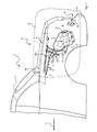
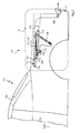
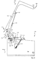
In Fig. 1 ist ein Cabriolet-Fahrzeug 1 eines ersten Ausführungsbeispiels in abgebrochener
Darstellung gezeigt, das mit einem bereichsweise flexiblen oder insgesamt
als Festverdeck ausgebildeten Dach 2 versehen ist. Das Dach 2 ist im rückwärtigen
Fahrzeugbereich 3 unterhalb eines Deckelteils 4 ablegbar. Dieses überdeckt bei
geöffnetem Dach 2 in Doppelfunktion sowohl einen Aufnahmeraum 5 für das geöffnete
Dach 2 als auch einen Gepäckaufnahmeraum 6.1 shows a convertible vehicle 1 of a first exemplary embodiment in broken form
Representation shown that is flexible with some areas or
Das Deckelteil 4 kann zur Freigabe einer Dachaufnahmeöffnung 7 (Fig. 3, Fig. 4)
gegen die Fahrtrichtung F in einem spitzen Winkel α öffnen. Weiterhin ist ein gegensinniges
Öffnen (Fig. 5, Fig. 6) des Deckelteils 4 unter Einschluß eines stumpfen
Winkels β mit der Fahrtrichtung F zur Freigabe einer Aufnahmeöffnung 8 zum Beoder
Entladen des Kofferraums 6 möglich. Das Deckelteil 4 ist in seinem rückwärtigen
Endbereich 9 an einer Scharniervorrichtung 10 gehalten, die eine Festlegung
des Deckelteils 4 sowohl bei vollständig geschlossenem Zustand (Fig. 1, Fig. 2) als
auch bei Freigabe der Durchtrittsöffnung 7 für das Dach 2 (Fig. 3, Fig. 4) sicherstellt.
Die Scharniervorrichtung 10 ist, insbesondere um kleine Spaltmaße im Übergang
zwischen dem Deckelteil 4 und einer Stoßstange S sicherzustellen, als reine
Schwenkbewegung ausgebildet.The
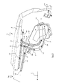
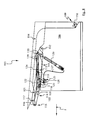
Das Deckelteil 4 ist außer über das rückwärtige Scharnier 10 noch über einen Hilfsrahmen
11 gehalten, der in seinem rückwärtigen Bereich über ein Schwenklager 12
an der Fahrzeugkarosserie schwenkbar gehalten ist. Der Hilfsrahmen 11 umfaßt
zwei den Fahrzeugseiten zugeordnete und sich vom Schwenklager 12 in Fahrtrichtung
F entlang zweier vertikaler Längsebenen erstreckende Seitenarme 13, die an
ihrem vorgeordneten, dem Schwenklager 12 abgewandten Ende mit einem Mehrgelenk
14 verbunden sind, das anderenends mit dem vorderen Endbereich 4a des
Deckelteils 4 in Verbindung steht.In addition to the
Das Mehrgelenk 14 umfaßt im Ausführungsbeispiel zwei miteinander gekoppelte
Teilgelenke 15,16, von denen eines dem Deckelteil 4 und das andere dem Hilfsrahmen
11 zugeordnet ist. Die Teilgelenke 15,16 sind über einen in sich starren Koppelkörper
17 miteinander verbunden. Der Koppelkörper 17 ist als in der Bewegungsebene
der seitlichen Arme 13 liegender, mehrfach abgewinkelter Lenker ausgebildet.
Er ist in geöffneter Stellung des Deckelteils 4 zur Freigabe der Durchtrittsöffnung
7 für das Dach 2 frei beweglich und nur über die Teilgelenke 15 und 16 gehalten.
In geschlossener Stellung des Deckelteils 4 sowie in Öffnungsstellung zur Freigabe
der Aufnahmeöffnung 8 für Gepäck ist der Koppelkörper 17 über einen vorderseitig
mit diesem starr verbundenen Riegel 18 in einem Schloß 18b blockiert. In diesen
Stellungen ist daher eine Bewegung des Koppelkörpers 17 nicht möglich.The multi-joint 14 comprises two coupled to each other in the embodiment
Das Teilgelenk 15 ist ebenso wie das Teilgelenk 16 im Ausführungsbeispiel als Viergelenk
ausgebildet, was allerdings nicht zwingend ist. Das Teilgelenk 15 umfaßt
zwei am Deckelteil 4 gelagerte Gelenkpunkte 19,20 und zwei am Koppelkörper 17
angeordnete Gelenkpunkte 21,22. Zur Verbindung von Deckelteil 4 und Koppelkörper
17 sind die Gelenkpunkte 19 und 21 über einen Lenker 23, die Gelenkpunkte 20
und 22 über einen weiteren Lenker 24 miteinander verbunden.The partial joint 15 is like the partial joint 16 in the exemplary embodiment as a four-bar linkage
trained, but this is not mandatory. The partial joint 15 comprises
two articulation points 19, 20 mounted on the
Das untere Teilgelenk 16 umfaßt zwei dem Koppelkörper zugeordnete Gelenkpunkte
25 und 26 sowie zwei dem seitlichen Arm 13 zugeordnete Gelenkpunkte 27 und 28.
Zur Verbindung von Koppelkörper 17 und seitlichem Arm 13 sind die Gelenkpunkte
25 und 27 über einen Lenker 29 und die Gelenkpunkte 26 und 28 über einen Lenker
30 miteinander verbunden.The lower joint 16 comprises two articulation points assigned to the
Alle Gelenkpunkte 19,20,21,22,25,26,27,28 sind an dem jeweiligen Bauteil (Deckelteil
4 bzw. Koppelkörper 17 bzw. Seitenarm 13) um bezüglich des jeweiligen Bauteils
ortsfeste Schwenkachsen schwenkbar angeordnet.All pivot points 19, 20, 21, 22, 25, 26, 27, 28 are on the respective component (cover
In geschlossener Stellung (Fig. 2) befinden sich die Lenker 23 und 24 in einer nahezu
horizontalen Stellung, die Lenker 29 und 30 des dem Hilfsrahmen 11 zugeordneten
Teilgelenks 16 sind hingegen nahezu vertikal. Der Koppelkörper 17, an dem
die Anlenkung der Lenker 23,29,24,30, nämlich die Gelenkpunkte 21,25,22,26 alternierend
aufeinander folgen, liegt nahezu horizontal. In the closed position (Fig. 2), the
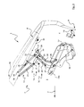
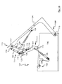
Durch Öffnung des seitlichen Arms 13 des Hilfsrahmens 11 über ein Antriebsorgan
31, beispielsweise einen Hydraulikzylinder, zur Freigabe der Durchtrittsöffnung 7 für
das Dach 2 wird eine Verlagerung des Teilgelenks 16 um die rückwärtige Anlenkung
12 des seitlichen Arms 13 in eine gegen die Fahrtrichtung F weisende Richtung
bewirkt. Die beiden dem Koppelkörper 17 zugeordneten Gelenkpunkte 25,26 werden
ebenfalls nach hinten verlagert, wobei der Koppelkörper 17 durch Freigabe des
Schlosses 18b beweglich wird.By opening the
Zudem wird der Koppelkörper 17 im spitzen Winkel gegenüber der Fahrtrichtung F
verkippt, wobei der Gelenkpunkt 26 gegenüber dem Gelenkpunkt 25 abwärts gezogen
wird. Dadurch, daß die Gelenkpunkte des oberen Teilgelenks 15 und des unteren
Teilgelenks 16 alternierend aufeinander folgen und der Gelenkpunkt 22 des
Lenkers 24 zwischen den Gelenkpunkten 25 und 26 gelegen ist, wird dieser ebenfalls
gegenüber dem Gelenkpunkt 21 des vorderen Lenkers 23 des oberen Teilgelenks
15 nach unten verlagert. Das Teilgelenk 15 stellt sich daher vertikal auf (Fig.
4), d. h., daß die Lenker 23,24 durch die unterschiedliche Verlagerung ihrer Gelenkpunkte
21,22 in Richtung der Pfeile 32,33 in die vertikale Endstellung gemäß Fig. 4
gelangen, in der das Mehrgelenk 14 insgesamt aufgestellt ist, auch wenn das untere
Teilgelenk 16 gegenüber der Ausgangsstellung (Fig. 1, Fig. 2) keine vertikale Aufstellung
seiner Lenker 29,30 erfahren hat. Vielmehr sind diese Lenker nur geringfügig
in ihrer Winkelstellung gegenüber dem Lot verändert, haben jedoch die Kippbewegung
des Koppelkörpers 17 und damit die Aufstellung des Gelenkpunkts 21 gegenüber
dem Gelenkpunkt 22 bewirkt.In addition, the
Somit ist insgesamt für das Mehrgelenk 14 eine Schwenk- und Hubbewegung erreicht. A pivoting and lifting movement is thus achieved overall for the multi-joint 14.
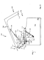
Durch die schwanenhalsartige Aufwärtskrümmung des seitlichen Arms 13 ist der
benötigte Raum im Heckbereich 3 sehr gering. Die seitlichen Arme 13 können extrem
kurz gehalten werden. Zudem kann das Hauptlager 12 in einer niedrigen Lage
innerhalb der Karosserie angeordnet werden.Due to the gooseneck-like upward curvature of the
Die Hilfsrahmen 11 mit den Antriebsorganen 31 und den Lagern 12 können insgesamt
als Module in seitlich vom Kofferraum 6 angeordneten Seitentaschen eingesetzt
werden. Dadurch, daß das untere Teilgelenk 16 bezüglich seiner Winkelstellung
der Lenker 29,30 gegenüber dem Lot sich bei Öffnung nur wenig ändert, kann
die Seitentasche nach vorne begrenzt sein, so daß wenig Kofferraum verlorengeht.
Die Lenker 23,24 des dem Deckelteil 4 zugeordneten Teilgelenks 15 können in
geschlossener Stellung dadurch, daß der Kopplungskörper 17 im Bereich der Oberkante
des Kofferraums 6 unmittelbar unterhalb des Deckelteils 4 gehalten ist, dicht
an das Deckelteil 4 angelegt sein, so daß auch hier wenig Raum verlorengeht.The
Zur Freigabe der Aufnahmeöffnung 8 für Gepäck (Fig. 5, Fig. 6) bleibt das Schloß
18b in seiner arretierten Stellung. Der Koppelkörper 17, der mit dem Riegel 18 verbunden
ist, verbleibt daher unbeweglich. Das untere Teilgelenk 16 ist daher an einer
Bewegung gehindert. Lediglich das obere Viergelenk 15 kann geöffnet werden, wobei
die dem Koppelkörper 17 zugeordneten Gelenkpunkte 21,22 ortsfest und lediglich
schwenkbeweglich verbleiben. Es öffnet also insgesamt nur das obere Teilgelenk
15, d. h., daß sich die Lenker 23,24 aufstellen und somit nur die Gelenkpunkte
19,20 verlagert werden. Zur Unterstützung der Öffnungsbewegung ist ein Gasdruckzylinder
34 vorgesehen. Auch ein Hydraulikzylinder oder ein ähnliches Unterstützungsorgan
kommt in Betracht. Der Gasdruckzylinder 34 ist hier am Lenker 24 angelenkt.
Dadurch liegt er bei geschlossenem Deckelteil 4 dicht an diesem in einer
nahezu horizontalen Stellung, so daß das Kofferraumvolumen nicht eingeschränkt
ist.To release the receiving
Das Öffnen zur Freigabe der Aufnahmeöffnung 8 für Gepäck entspricht daher der
Überlagerung einer Schwenk- und Hubbewegung bei einem üblichen Viergelenk.The opening to release the receiving
Mit der Erfindung ist ein sehr kurzer seitlicher Arm 13 realisiert, der aufgrund seines
geringen Trägheitsmoments leicht zu bewegen ist und sehr raumsparend in seitlichen
Taschen neben dem Kofferraum 6 angeordnet werden kann.With the invention, a very
Durch die Zwangskopplung der Teilgelenke 15,16 über den Koppelkörper 17 ist
weiterer Steueraufwand zum Erreichen der überlagerten Hub- und Schwenkbewegung
zur Freigabe der Durchtrittsöffnung 7 für Gepäck bei Öffnung des Deckelteils 4
entbehrlich. Auch das Schloß 18b kann über den Hydraulikzylinder 31 zum Schwenken
des Hilfsarms 11 entriegelt werden.Due to the positive coupling of the
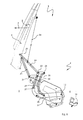
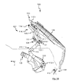
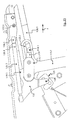
In Fig. 7 ist ein Cabriolet-Fahrzeug 101 eines zweiten Ausführungsbeispiels in abgebrochener
Darstellung gezeigt, das ebenfalls mit einem bereichsweise flexiblen oder
insgesamt als Festverdeck ausgebildeten Dach 102 versehen ist. Dieses ist im
rückwärtigen Fahrzeugbereich 103 unter einem Deckelteil 104 ablegbar. Das
Deckelteil 104 ist prinzipiell gleichartig oder ähnlich wie das Deckelteil 4 des ersten
Ausführungsbeispiels und überdeckt auch hier in Doppelfunktion sowohl einen Verdeckaufnahmeraum
105, in dem das Dach 102 in geöffneter Stellung gehalten ist,
als auch einen Gepäckaufnahmeraum 106.FIG. 7 shows a
Das Deckelteil 104 kann ebenso zur Freigabe einer Dachaufnahmeöffnung 107
(Fig. 9, Fig. 10) gegen die Fahrtrichtung F in einem spitzen Winkel öffnen. The
Weiterhin ist auch ein gegensinniges Öffnen (Fig. 11, Fig. 12) des Deckelteils 104
unter Einschluß eines stumpfen Winkels mit der Fahrtrichtung F zur Freigabe einer
Aufnahmeöffnung 108 zum Be- oder Entladen des Kofferraums 106 möglich. Das
Deckelteil 104 ist in seinem rückwärtigen Endbereich 109 an einer wie im ersten
Ausführungsbeispiel ausgebildeten Scharniervorrichtung 110 gehalten, die eine
Festlegung des Deckelteils 104 sowohl bei vollständig geschlossenem Zustand
(Fig. 7) als auch bei Öffnung der Durchtrittsöffnung für das Dach 102 (Fig. 9, 10)
sicherstellt.Furthermore, the
Das Deckelteil 104 ist außer über das rückwärtige Scharnier 110 noch über einen
Hilfsrahmen 111 gehalten, der in seinem rückwärtigen Bereich über ein Schwenklager
112 an der Fahrzeugkarosserie beweglich gehalten ist. Der Hilfsrahmen 111
umfaßt zwei den Fahrzeugseiten zugeordnete und sich vom Schwenklager 112 in
Fahrtrichtung F erstreckende Seitenarme 113, die an ihrem dem Schwenklager 112
abgewandten Ende mit einem Mehrgelenk 114 verbunden sind, das anderenends
mit dem vorderen Endbereich 115 des Deckelteils 104 in Verbindung steht.The
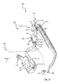
Das Mehrgelenk 114 ist in den hier gezeigten Ausführungsbeispielen als Viergelenk
ausgebildet, was allerdings nicht zwingend ist, und umfaßt zwei dem Deckelteil 104
zugeordnete Gelenkpunkte 116,117 sowie zwei den Seitenarmen 113 des Hilfsrahmens
111 zugeordnete Gelenkpunkte 118,119.The multi-joint 114 is in the exemplary embodiments shown here as a four-joint
formed, which is not mandatory, however, and comprises two the cover part 104th
associated hinge points 116, 117 and two of the
Zur Verbindung von Deckelteil 104 und Hilfsrahmen 111 sind die Gelenkpunkte 116
und 118 mittels eines Lenkers 120, die Gelenkpunkte 117 und 119 mittels eines
Lenkers 121 verbunden. The hinge points 116 are for connecting the
Die Gelenkpunkte 116 und 117 sind am Deckelteil 104 jeweils ortsfest angeordnet,
die hilfsrahmenseitigen Gelenkpunkte 118 und 119 sind über einen weiteren Lenker
122, der den gleichbleibenden Abstand zwischen diesen Gelenkpunkten sicherstellt,
miteinander verbunden, jedoch gemeinsam gegenüber dem Hilfsrahmen 111 verlagerbar.
Hierfür sind den Gelenkpunkten 118,119 Achsstummel zugeordnet, die in
Führungskulissen 123,124 der Seitenarme 113 des Hilfsrahmens 111 verschieblich
sind.The articulation points 116 and 117 are each arranged in a stationary manner on the
Die Führungskulissen 123,124 erstrecken sich in geschlossener Stellung des Hilfsrahmens
111 in Fahrtrichtung F und schwenken mit den Seitenarmen 113 des Hilfsrahmens
111 in eine aufwärts weisende Stellung bei Öffnung des Deckelteils 104
zur Freigabe der Durchtrittsöffnung 107 für das Dach (Fig. 9, 10).The
Es ist weiterhin ein Schloß 125 vorgesehen, das das Deckelteil 104 über Festlegung
der Gelenkpunkte 118,119 in geschlossener Stellung (Fig. 8) arretiert. Durch Ausschub
der Kolbenstange des Hydraulikzylinders 126, der die Aufwärtsbewegung des
Seitenarms 113 zur Freigabe der Durchtrittsöffnung 107 für das Dach 102 bewirkt,
wird über einen Bowdenzug 127 das Schloß 125 gelöst, so daß ein hiervon gehaltener
Querriegel 128, der mit dem Lenker 122 verbunden ist und die Gelenkpunkte
118 und 119 in geschlossener Position hält, außer Eingriff gebracht wird und das
vordere Ende des Deckelteils 104 abheben kann durch weiteren Ausschub der Kolbenstange
des Hydraulikzylinders 126.A
In geschlossener Stellung (Fig. 8) befinden sich die Gelenkpunkte 118,119 in in
Fahrtrichtung F vorderer Extremalstellung in den Führungskulissen 123,124. Während
der Öffnung des Deckelteils 104 zur Freigabe der Durchtrittsöffnung für das
Dach 102 werden die Gelenkpunkte 118,119 zunächst in den Führungskulissen
123,124 entgegen der Fahrtrichtung F verlagert, dabei bewegen sich die Lenker
120,121 aus ihrer im wesentlichen horizontalen Lage in eine gegenüber dem Seitenarm
113 des Hilfsrahmens 111 abgewinkelte und aufwärts gerichtete Lage, wodurch
das Deckelteil 104 sich mit seinem vorderen Endbereich 115 vom Seitenarm
113 entfernt. Bei weiterer Öffnung des Deckelteils 104 in dem genannten Sinne (Fig.
10) gehen die Lenker 120,121 in eine im wesentlichen vertikale Stellung über, wodurch
der Abstand vom vorderen Ende des Seitenarms 113 des Hilfsrahmens 111
zum vorderen Ende 115 des Deckelteils 104 maximiert ist. Zudem schieben sich
dabei die Gelenkpunkte 118,119 in den Führungskulissen 123,124 wieder in die vordere
Extremalstellung, so daß die Verbindung aus Seitenarm 113 und Lenkern
120,121 eine maximal mögliche Länge erreicht. Die Anlenkpunkte 116,117 am
Deckelteil 104 liegen dabei in etwa über dem Hauptlager 112 des Hilfsrahmens 111.
Dieses kann daher sehr weit nach vorne verlagert werden, so daß rückwärtig dieses
Lagers 112 die volle Kofferraumbreite zur Verfügung steht und hinreichend Ladevolumen
oder Zugänglichkeit für die Rückleuchten verbleibt.In the closed position (FIG. 8), the articulation points 118, 119 are in
Direction of travel F front extreme position in the
Zur Freigabe der Aufnahmeöffnung 108 für Gepäck (Fig. 11, 12) bleibt das Schloß
125 in seiner arretierten Stellung. Der mit dem Lenker 122 verbundene Querriegel
128 verbleibt daher unbeweglich. Somit können auch die Gelenkpunkte 118 und 119
nicht bewegt werden. Es ist daher nur eine reine Schwenkbewegung um diese Gelenkpunkte
möglich, die in der vorderen Extremalstellung in den Führungskulissen
123 und 124 verbleiben. Auch hier öffnet das Mehrgelenk 114, d. h., daß sich die
Lenker 120 und 121 aufstellen. Somit ist insgesamt eine Schwenk- mit überlagerter
Hubbewegung erreicht. Dieses entspricht dem üblichen Öffnen eines Mehrgelenks.The lock remains to release the receiving
Zur Unterstützung der Öffnungsbewegung ist ein Gasdruckzylinder 129 vorgesehen,
der sich einenends am Lenker 120 und anderenends an einem Lager 130 am
Deckelteil 104 abstützt. Auch eine andere Anordnung des Gasdruckzylinders 129
oder eines ähnlichen Unterstützungsorgans, beispielsweise eines Hydraulikzylinders,
kommt in Betracht. Bei der hier gezeigten Anordnung ist in Ruhestellung (Fig.
7, Fig. 8) der Gasdruckdämpfer 129 im Bereich der seitlichen Arme 113 gehalten,
auch der Anlenkpunkt 130 am Deckelteil 104 liegt in Fahrtrichtung F vor dem
Hauptlager 112, so daß die Einschränkung des Kofferraumvolumens durch den
Gasdruckdämpfer 129 in geschlossener Stellung des Deckelteils 104 minimiert ist.A
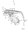
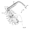
In einem dritten Ausführungsbeispiel (Fig. 17 bis Fig. 23) ist ebenfalls ein Viergelenk
114.1 vorgesehen, das zwei gegenüber dem Deckelteil 104 ortsfest angeordnete
Gelenkpunkte 116.1 und 117.1 sowie zwei dem Hilfsrahmen 111.1 zugeordnete
Gelenkpunkte 118.1 und 119.1 aufweist.In a third exemplary embodiment (FIGS. 17 to 23) there is also a four-bar linkage
114.1 provided, the two fixedly arranged opposite the
Zur Verbindung von Deckelteil 104 und Hilfsrahmen 111.1 sind die Gelenkpunkte
116.1 und 118.1 mittels eines Lenkers 120.1, die Gelenkpunkte 117.1 und 119.1 mittels
eines Lenkers 121.1 verbunden.The hinge points are for connecting the
Die hilfsrahmenseitigen Gelenkpunkte 118.1 und 119.1 sind über einen weiteren Lenker 122.1, der den gleichbleibenden Abstand zwischen diesen Gelenkpunkten sicherstellt, miteinander verbunden, jedoch gegenüber dem Hilfsrahmen 111.1 gemeinsam verlagerbar. Hierfür sind die Gelenkpunkte 118.1 und 119.1 als Achsstummel ausgebildet und in einer gemeinsamen, gekrümmten Führungskulisse 123.1 im Seitenarm 113.1 des Hilfsrahmens 111.1 verschieblich.The subframe-side pivot points 118.1 and 119.1 are over another Handlebar 122.1, the constant distance between these pivot points ensures, connected to each other, but common to the subframe 111.1 displaced. The articulation points 118.1 and 119.1 are stub axles for this trained and in a common, curved guide backdrop 123.1 slidable in the side arm 113.1 of the subframe 111.1.
Die Führungskulisse 123.1 erstreckt sich in geschlossener Stellung des Hilfsrahmens
111.1 in Fahrtrichtung F, wobei sie sich von einem heckseitigen Ende nach
vorne hin leicht aufwärts gekrümmt verläuft. Sie schwenkt mit den Seitenarmen
113.1 bei Öffnung des Deckelteils 104.1 zur Freigabe der Durchtrittsöffnung 107 für
das Dach (Fig. 18, Fig. 19) in eine aufwärts weisende Stellung. Auch bei der Alternatiwersion
ist ein Schloß 125 vorgesehen, das das Deckelteil 104 in geschlossener
Stellung (Fig. 17) arretiert. Nach Lösung des Schlosses 125 kann ein Querriegel
128, der mit dem Lenker 122.1 verbunden ist und die Gelenkpunkte 118.1 und 119.1
in geschlossener Position hält, außer Eingriff gelangen, und das vordere Ende 115
des Deckelteils 104 kann abheben.The guide link 123.1 extends in the closed position of the subframe
111.1 in the direction of travel F, moving from a rear end
slightly curved upwards at the front. She swings with the side arms
113.1 when opening the cover part 104.1 to open the
In geschlossener Stellung (Fig. 17) befinden sich die Gelenkpunkte 118.1 und 119.1
in in Fahrtrichtung F hinterer Extremalstellung in der Führungskulisse 123.1. Während
der Öffnung des Deckelteils 104 zur Freigabe der Durchtrittsöffnung 107 für
das Dach 102 werden die Gelenkpunkte 118.1 und 119.1 in der gemeinsamen Führungskulisse
123.1 in Fahrtrichtung F verlagert, dabei bewegen sich die Lenker
120.1 und 121.1 aus ihrer im wesentlichen horizontalen Lage in eine gegenüber dem
Seitenarm 113.1 des Hilfsrahmens 111.1 abgewinkelte und aufwärts gerichtete
Lage, wodurch das Deckelteil 104 sich mit seinem vorderen Endbereich 115 vom
Seitenarm 113.1 entfernt. Bei weiterer Öffnung des Deckelteils 104.1 in dem genannten
Sinne (Fig. 19) gelangen die Lenker 120.1 und 121.1 in eine im wesentlichen
vertikale Stellung, wodurch der Abstand vom vorderen Ende des Seitenarms
113.1 des Hilfsrahmens 111.1 zum vorderen Ende 115 des Deckelteils 104 maximiert
ist. Zudem schieben sich die Gelenkpunkte 118.1,119.1 in der Führungskulisse
123.1 in Richtung der vorderen Extremalstellung bezüglich der Führungskulisse
123.1, so daß die Verbindung aus Seitenarm 113 und Lenkern 120.1, 121.1 eine
maximal mögliche Länge erreicht. Die Anlenkpunkte 116.1,117.1 am Deckelteil
104.1 liegen dann in etwa über dem Hauptlager 112.1 des Hilfsrahmens 111.1. Dieses
Hauptlager kann auch in dieser Ausführungsform sehr weit nach vorne verlagert
sein. Zudem kann das Hauptlager 112.1 und das ihn tragende Gestänge 130 insgesamt
als Modul in eine Seitentasche der Fahrzeugkarosserie eingesetzt werden.The articulation points 118.1 and 119.1 are in the closed position (FIG. 17)
in extreme rear position in the direction of travel F in the guide link 123.1. While
the opening of the
Um die Verschieblichkeit der Gelenkpunkte 118.1 und 119.1 zu ermöglichen, sind
diese an abgewinkelten Lenkern 131,132 gelagert, wobei diese Lenker 131,132 anderenends
mit Rollen 133 verbunden sind, die in der Führungskulisse 123.1 verfahrbar
sind.To enable the articulation of the articulation points 118.1 and 119.1
these are mounted on
Die Ausbildung nach den Fig. 22 bis 24 zeigt leichte geometrische Abänderungen
der abgewinkelten Lenker 131 und 132. In jedem Fall sind diese gegenüber dem
Lenker 122.1 ortsfest und tragen an ihren den Rollen 134,135 abgewandten Enden
die Gelenkpunkte 118.1 und 119.1. An einem der Lenker 131 oder 132 kann zudem
eine Lagerung für einen Gasdruckdämpfer 129.1 zur Unterstützung der Freigabe der
Gepäckaufnahmeöffnung 108 vorgesehen sein.The formation according to FIGS. 22 to 24 shows slight geometric changes
the
Wie im zweiten Ausführungsbeispiel bleiben auch hier bei Öffnung des Deckelteils
104 zur Freigabe der Aufnahmeöffnung 108 für Gepäck die Gelenkpunkte 118.1 und
119.1 unbewegt, da das Schloß 125 für diese Bewegung nicht außer Eingriff gebracht
wird und daher die Rollen 134 und 135 in der Führungskulisse 123.1 nicht
beweglich sind. Es steht dann nur die normale Viergelenkversion ohne Verlagerung
der Gelenkpunkte zur Verfügung.As in the second embodiment, the cover part remains open
104 to release the
In jedem Fall ist eine weit vorne liegende Anlenkung 112,112.1 des Hilfsrahmens
111 bzw. 111.1 ermöglicht, wodurch die Öffnungskinematik des Deckelteils 104 verbessert
ist und im Heckbereich die räumlichen Verhältnisse großzügiger ausgebildet
sind. In any case there is an
Die Kräfte zum Öffnen des Deckelteils 104 sind zudem relativ gering, da nur ein kurzer
Hilfsrahmen 111 bzw. 111.1 bewegt werden muß, dessen Trägheitmoment gering
ist. Die Lenker 120,121 bzw. 120.1,121.1 öffnen automatisch durch die Verlagerung
der Gelenkpunkte 118,119 bzw. 118.1,119.1 gegenüber dem Hilfsrahmen 111
bzw. 111.1, so daß weitere Steuerungsmechanismen entbehrlich sind. Auch die
Entriegelung des Schlosses 125 erfolgt durch Ausschub der Kolbenstange des Hydraulikzylinders
126 automatisiert. Eine separate Ansteuerung des Schlosses 125 ist
nicht erforderlich.The forces for opening the
Claims (17)
Applications Claiming Priority (4)
| Application Number | Priority Date | Filing Date | Title |
|---|---|---|---|
| DE10051996 | 2000-10-20 | ||
| DE2000151996 DE10051996B4 (en) | 2000-10-20 | 2000-10-20 | Cabriolet vehicle with a can be placed in the rear of the vehicle area below a cover part roof |
| DE10052001 | 2000-10-20 | ||
| DE2000152001 DE10052001B4 (en) | 2000-10-20 | 2000-10-20 | Cabriolet vehicle with a can be placed in the rear of the vehicle area below a cover part roof |
Publications (3)
| Publication Number | Publication Date |
|---|---|
| EP1199202A2 true EP1199202A2 (en) | 2002-04-24 |
| EP1199202A3 EP1199202A3 (en) | 2003-05-07 |
| EP1199202B1 EP1199202B1 (en) | 2007-02-14 |
Family
ID=26007432
Family Applications (1)
| Application Number | Title | Priority Date | Filing Date |
|---|---|---|---|
| EP01124863A Expired - Lifetime EP1199202B1 (en) | 2000-10-20 | 2001-10-18 | Convertible vehicle with a roof storable beneath a cover element on the rear part of the vehicle |
Country Status (2)
| Country | Link |
|---|---|
| US (1) | US6824194B2 (en) |
| EP (1) | EP1199202B1 (en) |
Cited By (8)
| Publication number | Priority date | Publication date | Assignee | Title |
|---|---|---|---|---|
| FR2851546A1 (en) * | 2003-02-21 | 2004-08-27 | Renault Sa | Retractable roof assembly process for vehicle, e.g. car, involves placing trunk door on body shell and connecting it to lateral mechanisms, fixing the roof on the body shell, and fixing actuating mechanisms to breaker plate |
| WO2004076215A2 (en) * | 2003-02-21 | 2004-09-10 | Renault S.A.S. | Method for mounting a retractable roof and vehicle fitted with said roof |
| EP1785304A1 (en) * | 2005-11-15 | 2007-05-16 | Magna Car Top Systems GmbH | Vehicle with a vehicle roof adjustable between a closed position and a stored position |
| EP1816020A2 (en) * | 2006-02-01 | 2007-08-08 | Magna Car Top Systems GmbH | Convertible vehicle |
| FR2915724A1 (en) * | 2007-05-04 | 2008-11-07 | Heuliez Sa | MULTI-ARM HOOD FRONT AND REAR |
| FR2917699A1 (en) * | 2007-06-22 | 2008-12-26 | Heuliez Sa | ALTERNATIVE LOCK HOOD AND ASSOCIATED CONVERTIBLE VEHICLE |
| EP1964705A3 (en) * | 2007-02-28 | 2010-06-02 | Magna Car Top Systems GmbH | Boot lid for closing the storage space in the body work |
| US11896172B2 (en) | 2019-11-27 | 2024-02-13 | Duravit Aktiengesellschaft | Joint arrangement for the pivotable mounting of a lid, a seat or a seat/lid fitting on a ceramic sanitary article |
Families Citing this family (40)
| Publication number | Priority date | Publication date | Assignee | Title |
|---|---|---|---|---|
| DE10112344C1 (en) * | 2001-03-13 | 2002-08-29 | Cts Fahrzeug Dachsysteme Gmbh | Convertible top compartment lid in a convertible vehicle |
| DE10116613C1 (en) * | 2001-04-03 | 2002-07-18 | Cts Fahrzeug Dachsysteme Gmbh | Cabriolet vehicle has roof folding up and down through kinematic system and four articulated rods and coupling rod so that it moves within contours of vehicle |
| DE10116710C2 (en) * | 2001-04-04 | 2003-03-13 | Edscha Cabrio Dachsys Gmbh | Convertible top for a convertible vehicle |
| DE10135581A1 (en) * | 2001-07-20 | 2003-01-30 | Karmann Gmbh W | Cabriolet vehicle with a cover part in the rear area of the vehicle |
| DE10137018C1 (en) * | 2001-07-30 | 2003-02-20 | Daimler Chrysler Ag | Support frame of a trunk lid of a rear compartment of a body |
| FR2834487B1 (en) * | 2002-01-04 | 2004-02-20 | France Design | DEVICE FOR OPENING AND CLOSING THE COVER OF THE REAR TRUNK OF A DISCOVERABLE VEHICLE WITH FOLDABLE ROOF |
| DE10214980B4 (en) * | 2002-04-04 | 2007-04-12 | Magna Car Top Systems Gmbh | Rear lid for a convertible vehicle |
| US6799788B2 (en) * | 2002-04-08 | 2004-10-05 | Ssr Roofing Systems, Llc | Decklid mechanism for vehicle with retractable top |
| US6899368B2 (en) * | 2002-05-23 | 2005-05-31 | Wilhelm Karmann Gmbh | Decklid mechanism for vehicle with retractable top |
| DE20208001U1 (en) * | 2002-05-23 | 2003-10-02 | Karmann Gmbh W | Cabriolet vehicle with a roof that can be stored under a cover part |
| FR2840582B1 (en) * | 2002-06-11 | 2004-12-24 | France Design | REAR TRUNK COVER FOR VEHICLE WITH FOLDABLE ROOF |
| DE10249299B4 (en) * | 2002-10-22 | 2009-10-15 | Webasto Ag | Storage compartment cover of a convertible |
| DE10300342A1 (en) * | 2003-01-09 | 2004-07-22 | Wilhelm Karmann Gmbh | Convertible car |
| DE10300883B3 (en) * | 2003-01-13 | 2004-03-11 | Dr.Ing.H.C. F. Porsche Ag | Cover for closure for cabriolet vehicle roof has cover shell housing secured to closure via holder with ratchet openings for locating ratchet noses of closure |
| US6866327B2 (en) * | 2003-02-06 | 2005-03-15 | Asc Incorporated | Tonneau panel mechanism |
| US6857686B2 (en) | 2003-02-06 | 2005-02-22 | Asc Incorporated | Two-way opening decklid for a convertible roof vehicle |
| DE10309366B4 (en) * | 2003-03-03 | 2005-01-27 | Wilhelm Karmann Gmbh | Convertible car |
| US7198318B2 (en) * | 2003-03-24 | 2007-04-03 | Asc Incorporated | Retractable roof structural system |
| FR2856958B1 (en) * | 2003-07-02 | 2006-03-03 | France Design | REAR-LOCKING REAR LOCK HOOD WITH CONSTANT SUPPORT, AND VEHICLE THUS EQUIPPED |
| FR2856966B1 (en) * | 2003-07-02 | 2008-07-04 | France Design | REAR-LOCKED ARTICULTION REAR CHASSIS HOOD FOR A DISABLED VEHICLE WITH A FOLDING ROOF |
| DE10337353B4 (en) * | 2003-08-14 | 2011-09-29 | Wilhelm Karmann Gmbh | Convertible car |
| DE10337474A1 (en) * | 2003-08-14 | 2005-06-02 | Wilhelm Karmann Gmbh | Convertible car |
| DE10340017B3 (en) * | 2003-08-28 | 2004-08-12 | Cts Fahrzeug-Dachsysteme Gmbh | Rear cover for cabriolet automobile using multiple linkage mechanism for movement of rear cover between closed position and raised position providing access to storage compartment for cabriolet roof |
| DE10345276A1 (en) * | 2003-09-30 | 2005-04-21 | Karmann Gmbh W | motor vehicle |
| US7032952B2 (en) * | 2004-06-24 | 2006-04-25 | Asc Incorporated | Dual acting decklid |
| DE102004061828B4 (en) * | 2004-12-22 | 2006-10-12 | Wilhelm Karmann Gmbh | Motor vehicle with a movable cover part of the body |
| DE102005006272A1 (en) * | 2005-02-10 | 2006-08-17 | Wilhelm Karmann Gmbh | Motor vehicle with a lid part which can be opened in two senses |
| DE102005026489B4 (en) * | 2005-06-09 | 2017-11-30 | Valmet Automotive Oy | Convertible vehicle with a roof that can be stored in a convertible top compartment |
| DE102005033599B4 (en) * | 2005-07-14 | 2013-09-05 | Webasto Ag | Adjustment of a convertible top compartment cover of a convertible |
| DE102006007635B4 (en) * | 2006-02-18 | 2010-04-08 | Magna Car Top Systems Gmbh | Roof for a passenger car |
| US7762607B2 (en) * | 2006-12-21 | 2010-07-27 | Wilhelm Karmann Gmbh | Overcenter linkage mechanism for a decklid of an automotive vehicle |
| DE102006061489B4 (en) * | 2006-12-23 | 2011-07-28 | Magna Car Top Systems GmbH, 74321 | Trunk lid for a body of a motor vehicle |
| DE102007012673A1 (en) * | 2007-03-16 | 2008-09-18 | Wilhelm Karmann Gmbh | Motor vehicle i.e. cabriolet vehicle, has body part mounted detachably opposite to vehicle, and lock provided with movable closing units for mounting body part at rotation axis, where closing units are filled in closing position of axis |
| US20090224567A1 (en) * | 2008-03-07 | 2009-09-10 | Mazda Motor Corporation | Baggage compartment structure of vehicle |
| JP5245610B2 (en) * | 2008-07-28 | 2013-07-24 | アイシン精機株式会社 | Panel moving device |
| DE102008047285B4 (en) * | 2008-09-16 | 2019-02-28 | Dr. Ing. H.C. F. Porsche Aktiengesellschaft | Top compartment lid |
| DE102009006721B4 (en) * | 2009-01-29 | 2016-04-28 | Audi Ag | Actuation device for a top compartment lid |
| US8132840B2 (en) * | 2009-04-21 | 2012-03-13 | Wilhelm Karmann Gmbh | Center driven tonneau system |
| KR101488335B1 (en) * | 2013-09-26 | 2015-01-30 | 현대자동차주식회사 | Locking structure of trunk lid |
| US10239392B2 (en) * | 2014-07-30 | 2019-03-26 | Dr. Ing. H.C.F. Porsche Aktiengesellschaft | Arrangement of a cover of a folding-top compartment in a cabriolet |
Citations (1)
| Publication number | Priority date | Publication date | Assignee | Title |
|---|---|---|---|---|
| DE19756062C1 (en) | 1997-12-17 | 1999-04-01 | Daimler Benz Ag | Cabriolet motor vehicle hood |
Family Cites Families (9)
| Publication number | Priority date | Publication date | Assignee | Title |
|---|---|---|---|---|
| DE4445944C1 (en) * | 1994-12-22 | 1996-04-25 | Daimler Benz Ag | Hard top motor car |
| DE19613917C2 (en) * | 1996-04-06 | 1998-01-15 | Daimler Benz Ag | Cover arrangement for a convertible top compartment arranged in the rear area of a vehicle |
| DE19803155C1 (en) * | 1998-01-28 | 1999-08-12 | Daimler Chrysler Ag | Rear lid mounting for convertible motor vehicle |
| JP2000104445A (en) * | 1998-09-29 | 2000-04-11 | Toyota Motor Corp | Opening and closing mechanism of luggage |
| JP2000211373A (en) * | 1999-01-27 | 2000-08-02 | Takada Kogyo Kk | Trunk lid opening and closing controller |
| DE19910763C1 (en) * | 1999-03-11 | 2000-07-13 | Daimler Chrysler Ag | Motor vehicle boot lid operator comprizes strut tubes whose locking wedge is freed or engaged with receiver mounting by pulling respective bowden cable ties off hydraulic cylinder. |
| DE60002772T2 (en) * | 1999-03-26 | 2004-08-19 | Cts Fahrzeug-Dachsysteme Gmbh | Swiveling cover for vehicles |
| US6217104B1 (en) * | 1999-06-16 | 2001-04-17 | Cts Fahrzeug Dachsysteme Gmbh | Retractable hard top module |
| JP3523816B2 (en) * | 1999-10-19 | 2004-04-26 | アイシン精機株式会社 | Luggage panel opening and closing device |
-
2001
- 2001-10-18 EP EP01124863A patent/EP1199202B1/en not_active Expired - Lifetime
- 2001-10-18 US US09/982,563 patent/US6824194B2/en not_active Expired - Fee Related
Patent Citations (1)
| Publication number | Priority date | Publication date | Assignee | Title |
|---|---|---|---|---|
| DE19756062C1 (en) | 1997-12-17 | 1999-04-01 | Daimler Benz Ag | Cabriolet motor vehicle hood |
Cited By (12)
| Publication number | Priority date | Publication date | Assignee | Title |
|---|---|---|---|---|
| FR2851546A1 (en) * | 2003-02-21 | 2004-08-27 | Renault Sa | Retractable roof assembly process for vehicle, e.g. car, involves placing trunk door on body shell and connecting it to lateral mechanisms, fixing the roof on the body shell, and fixing actuating mechanisms to breaker plate |
| WO2004076215A2 (en) * | 2003-02-21 | 2004-09-10 | Renault S.A.S. | Method for mounting a retractable roof and vehicle fitted with said roof |
| WO2004076215A3 (en) * | 2003-02-21 | 2004-11-04 | Renault Sa | Method for mounting a retractable roof and vehicle fitted with said roof |
| EP1785304A1 (en) * | 2005-11-15 | 2007-05-16 | Magna Car Top Systems GmbH | Vehicle with a vehicle roof adjustable between a closed position and a stored position |
| US7537266B2 (en) | 2005-11-15 | 2009-05-26 | Magna Car Top Systems Gmbh | Vehicle roof adjustable between closed and storage positions |
| EP1816020A2 (en) * | 2006-02-01 | 2007-08-08 | Magna Car Top Systems GmbH | Convertible vehicle |
| EP1816020A3 (en) * | 2006-02-01 | 2009-07-22 | Magna Car Top Systems GmbH | Convertible vehicle |
| US7900992B2 (en) | 2006-02-01 | 2011-03-08 | Magna Car Top Systems Gmbh | Trunk lid link assembly for convertible vehicle |
| EP1964705A3 (en) * | 2007-02-28 | 2010-06-02 | Magna Car Top Systems GmbH | Boot lid for closing the storage space in the body work |
| FR2915724A1 (en) * | 2007-05-04 | 2008-11-07 | Heuliez Sa | MULTI-ARM HOOD FRONT AND REAR |
| FR2917699A1 (en) * | 2007-06-22 | 2008-12-26 | Heuliez Sa | ALTERNATIVE LOCK HOOD AND ASSOCIATED CONVERTIBLE VEHICLE |
| US11896172B2 (en) | 2019-11-27 | 2024-02-13 | Duravit Aktiengesellschaft | Joint arrangement for the pivotable mounting of a lid, a seat or a seat/lid fitting on a ceramic sanitary article |
Also Published As
| Publication number | Publication date |
|---|---|
| US20020093218A1 (en) | 2002-07-18 |
| EP1199202A3 (en) | 2003-05-07 |
| EP1199202B1 (en) | 2007-02-14 |
| US6824194B2 (en) | 2004-11-30 |
Similar Documents
| Publication | Publication Date | Title |
|---|---|---|
| EP1199202A2 (en) | Convertible vehicle with a roof storable beneath a cover element on the rear part of the vehicle | |
| EP1279540B1 (en) | Convertible vehicles with a cover part in the rear vehicle area | |
| EP1302351B1 (en) | Storable roof for convertible vehicle | |
| EP1197368B1 (en) | Multipart cover for vehicle | |
| EP1112879B1 (en) | Convertible vehicle roof | |
| EP1308333B1 (en) | Storable roof for convertible vehicle | |
| EP1762414B1 (en) | Roof for cabriolet | |
| EP1356969B1 (en) | Convertible vehicle with a roof comprising at least a rigid rear end portion | |
| DE10324757B3 (en) | Device for selectively moving a tailgate of a vehicle from a closed position into a receiving position and into a loading position | |
| DE10051996B4 (en) | Cabriolet vehicle with a can be placed in the rear of the vehicle area below a cover part roof | |
| EP1940640B1 (en) | Locking mechanism for a folding top compartment cover of a convertible | |
| EP1554150B1 (en) | Hood compartment cover for a cabriolet vehicle with a retractable hood | |
| DE102004038221B4 (en) | Hood for a convertible vehicle | |
| DE10052001B4 (en) | Cabriolet vehicle with a can be placed in the rear of the vehicle area below a cover part roof | |
| DE10337353B4 (en) | Convertible car | |
| DE10242502B4 (en) | Adjustable vehicle roof | |
| DE60118480T2 (en) | MOTOR VEHICLE WITH A REFILLABLE ROOF IN PARTICULAR OF THE GENERATION THAT MAKES A CONVERSION FROM THE CABRIO TO THE COUPE AND VICE VERSA | |
| EP1284211B1 (en) | Motor vehicle with movable roof | |
| EP2383135B1 (en) | Movable cover | |
| DE102005033843A1 (en) | vehicle | |
| DE102006052089B4 (en) | Cabriolet vehicle with convertible top that can be stored in a top storage compartment | |
| DE10315102B4 (en) | Locking device for the closed position of vehicle parts | |
| DE102004024235B4 (en) | Hood for a convertible vehicle | |
| DE102007031773B4 (en) | Cabriolet vehicle with a storable under a movable cover part roof | |
| EP1634750B1 (en) | Convertible car |
Legal Events
| Date | Code | Title | Description |
|---|---|---|---|
| PUAI | Public reference made under article 153(3) epc to a published international application that has entered the european phase |
Free format text: ORIGINAL CODE: 0009012 |
|
| AK | Designated contracting states |
Kind code of ref document: A2 Designated state(s): AT BE CH CY DE DK ES FI FR GB GR IE IT LI LU MC NL PT SE TR |
|
| AX | Request for extension of the european patent |
Free format text: AL;LT;LV;MK;RO;SI |
|
| PUAL | Search report despatched |
Free format text: ORIGINAL CODE: 0009013 |
|
| AK | Designated contracting states |
Designated state(s): AT BE CH CY DE DK ES FI FR GB GR IE IT LI LU MC NL PT SE TR |
|
| AX | Request for extension of the european patent |
Extension state: AL LT LV MK RO SI |
|
| RIC1 | Information provided on ipc code assigned before grant |
Ipc: 7B 60J 7/20 A Ipc: 7B 62D 25/12 B |
|
| 17P | Request for examination filed |
Effective date: 20030626 |
|
| AKX | Designation fees paid |
Designated state(s): DE FR GB IT |
|
| GRAP | Despatch of communication of intention to grant a patent |
Free format text: ORIGINAL CODE: EPIDOSNIGR1 |
|
| REG | Reference to a national code |
Ref country code: DE Ref legal event code: 8566 |
|
| GRAS | Grant fee paid |
Free format text: ORIGINAL CODE: EPIDOSNIGR3 |
|
| GRAA | (expected) grant |
Free format text: ORIGINAL CODE: 0009210 |
|
| AK | Designated contracting states |
Kind code of ref document: B1 Designated state(s): FR GB IT |
|
| REG | Reference to a national code |
Ref country code: GB Ref legal event code: FG4D Free format text: NOT ENGLISH |
|
| GBT | Gb: translation of ep patent filed (gb section 77(6)(a)/1977) |
Effective date: 20070521 |
|
| ET | Fr: translation filed | ||
| PLBE | No opposition filed within time limit |
Free format text: ORIGINAL CODE: 0009261 |
|
| STAA | Information on the status of an ep patent application or granted ep patent |
Free format text: STATUS: NO OPPOSITION FILED WITHIN TIME LIMIT |
|
| 26N | No opposition filed |
Effective date: 20071115 |
|
| PGFP | Annual fee paid to national office [announced via postgrant information from national office to epo] |
Ref country code: IT Payment date: 20121023 Year of fee payment: 12 |
|
| PGFP | Annual fee paid to national office [announced via postgrant information from national office to epo] |
Ref country code: GB Payment date: 20131030 Year of fee payment: 13 Ref country code: FR Payment date: 20131030 Year of fee payment: 13 |
|
| PG25 | Lapsed in a contracting state [announced via postgrant information from national office to epo] |
Ref country code: IT Free format text: LAPSE BECAUSE OF NON-PAYMENT OF DUE FEES Effective date: 20131018 |
|
| REG | Reference to a national code |
Ref country code: GB Ref legal event code: 732E Free format text: REGISTERED BETWEEN 20140925 AND 20141001 |
|
| REG | Reference to a national code |
Ref country code: FR Ref legal event code: TP Owner name: VALMET AUTOMOTIVE OY, FI Effective date: 20150105 |
|
| GBPC | Gb: european patent ceased through non-payment of renewal fee |
Effective date: 20141018 |
|
| PG25 | Lapsed in a contracting state [announced via postgrant information from national office to epo] |
Ref country code: GB Free format text: LAPSE BECAUSE OF NON-PAYMENT OF DUE FEES Effective date: 20141018 |
|
| REG | Reference to a national code |
Ref country code: FR Ref legal event code: ST Effective date: 20150630 |
|
| PG25 | Lapsed in a contracting state [announced via postgrant information from national office to epo] |
Ref country code: FR Free format text: LAPSE BECAUSE OF NON-PAYMENT OF DUE FEES Effective date: 20141031 |