EP1940640B1 - Locking mechanism for a folding top compartment cover of a convertible - Google Patents
Locking mechanism for a folding top compartment cover of a convertible Download PDFInfo
- Publication number
- EP1940640B1 EP1940640B1 EP06818031.4A EP06818031A EP1940640B1 EP 1940640 B1 EP1940640 B1 EP 1940640B1 EP 06818031 A EP06818031 A EP 06818031A EP 1940640 B1 EP1940640 B1 EP 1940640B1
- Authority
- EP
- European Patent Office
- Prior art keywords
- locking mechanism
- mechanism according
- top compartment
- support device
- lock
- Prior art date
- Legal status (The legal status is an assumption and is not a legal conclusion. Google has not performed a legal analysis and makes no representation as to the accuracy of the status listed.)
- Not-in-force
Links
Images


Classifications
-
- B—PERFORMING OPERATIONS; TRANSPORTING
- B60—VEHICLES IN GENERAL
- B60J—WINDOWS, WINDSCREENS, NON-FIXED ROOFS, DOORS, OR SIMILAR DEVICES FOR VEHICLES; REMOVABLE EXTERNAL PROTECTIVE COVERINGS SPECIALLY ADAPTED FOR VEHICLES
- B60J7/00—Non-fixed roofs; Roofs with movable panels, e.g. rotary sunroofs
- B60J7/20—Vehicle storage compartments for roof parts or for collapsible flexible tops
-
- B—PERFORMING OPERATIONS; TRANSPORTING
- B60—VEHICLES IN GENERAL
- B60J—WINDOWS, WINDSCREENS, NON-FIXED ROOFS, DOORS, OR SIMILAR DEVICES FOR VEHICLES; REMOVABLE EXTERNAL PROTECTIVE COVERINGS SPECIALLY ADAPTED FOR VEHICLES
- B60J7/00—Non-fixed roofs; Roofs with movable panels, e.g. rotary sunroofs
- B60J7/185—Locking arrangements
- B60J7/19—Locking arrangements for rigid panels
- B60J7/198—Locking arrangements for rigid panels for locking tonneau covers such as covers for roof storage compartments or for pick-up truck beds
Definitions
- the invention relates to a locking device for fixing a on the body by means of a drive means movably mounted support means of a top compartment lid of a convertible.
- a convertible which has a support means in its rear region, on the front side a top compartment lid is fixedly mounted and the rear side a tailgate is movably mounted by means of a bearing device.
- the support means is adjustable by means of a four-bar device on the body between a closed position and a rearwardly pivoted open position and locked by means of a lock device in its closed position on the body.
- the lock device contains on both sides in each case two locks spaced apart in the longitudinal direction, which are arranged on the carrier device and are connected to a common drive arranged on the carrier device.
- the front lock is arranged on the body and the rear lock on the support means and each lock is associated with its own drive.
- the tailgate can be locked by means of a tailgate lock, which is arranged in the region of the storage device of the tailgate.
- a convertible top compartment lid forming a tailgate or a boot lid is movably mounted by means of a hinge device on a subframe which is movably supported in a lowersammlungend Scheme via a vehicle-fixed pivot axis.
- the top compartment lid can be pivoted together with the subframe around the vehicle-fixed pivot axis to the rear, so that an opening for the top to be deposited is free.
- Boot lid the top compartment lid is pivotable about a front pivot axis.
- the invention has for its object to improve a locking device mentioned above in terms of improved functionality and simplified operation.
- the object is achieved in the above-mentioned locking device according to the invention by a body-mounted first lock unit for releasably locking the support means on the body, mounted on the support means second lock unit for releasably locking the movably mounted on the support device top compartment lid to the support means and an actuator for the Actuation of the two lock units.
- the carrier device with the top compartment lid which can also form a tailgate or a trunk lid, is provided for convertibles with a convertible hardtop or softtop roof, but can also be used in other vehicles.
- the actuating device is connected to the drive device adjusting the carrier device. Due to the derived from the drive device actuation thus an independent drive or drive motor is not required. Conveniently, the two lock units are arranged adjacent to each other, so that they can be operated by the common actuator without much effort.
- first lock unit and the second lock unit are connected in a releasable coupling engagement with each other, when the operation takes place. Due to the detachable coupling engagement, the two lock units or the units storing the lock units can be removed from each other in the course of the roof shelf when they perform the necessary movements.
- a locking hook of the first lock unit and a lock hook of the second lock unit can be coupled to each other via engagement elements in order to realize the joint operation.
- an actuating pin and a slot guide receiving the actuating pin form the engagement elements, but other types of engagement elements may be used.
- the latch hook and the lock hook can be mounted pivotally or slidably.
- the locking device is preferably formed such that the carrier device is held locked in a closed position by means of the first lock unit to the body, wherein the second lock unit has unlocked the top compartment lid of the support means.
- the actuating device formed in particular as a Bowden cable is connected to a latch hook of the first lock unit.
- the first lock unit or its latch hook can then be coupled via the coupling device or the engagement elements with the second lock unit or its lock hook.
- one or the lock hook of the second lock unit is biased by means of a biasing device in its closed position in which he the top compartment lid or a bearing part of the top compartment lid on the support means keeps locked. This closed position thus retains the lock hook, even if it is decoupled from the first lock unit.
- the top compartment lid is attached by means of a bracket to a console, which is movably mounted by means of a link device on the carrier device.
- An expedient design provides that the drive means is slidably guided along its end coupled to the actuating device along a guide and can be locked by means of a locking device in an end position in which the first lock unit is unlocked.
- a defined sequence of movements during pivoting of the carrier device and the top compartment lid is achieved, taking into account the retroactive weight of these components on the drive device.
- the locking means is operable by a lever movable by the drive means for driving the support means.
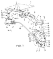
- a convertible has a top compartment lid 1 (the top compartment lid 1 is only in Fig. 1 shown in detail and schematically), which is provided for covering a rear-side top deck storage space and with its front edge (the in Fig. 1 Arrow marked x points in the vehicle longitudinal direction to the front) is raised to release a passage opening for between its closed position and its storage position to be adjusted folding roof or folding top, which may be a hardtop roof as well as a soft top roof.
- the folding-top compartment lid 1 is expediently also used as a boot lid, by being moved out of its closed position (FIG. Fig. 1 ) is pivoted with its rear edge relative to the body and thus releases a loading opening of the trunk.
- a comparable top compartment lid is disclosed, which is supported by a subframe on the body and is pivotally mounted according to the embodiment at the rear of the vehicle to a body-mounted pivot axis.
- the top compartment lid 1 is on both sides by means of a respective holder, the z. B. contains a plurality of bolts 2, attached to a bracket 3, which in turn pivotally mounted on one of two links 4 and 5 four-bar linkage to a support means, the z. B. is formed by a frame 6, which supports the console 3 and the four-bar linkage 4, 5.
- the description is made on the basis of the right side of the carrier device of the top compartment lid, which is constructed essentially symmetrically with respect to the vehicle longitudinal axis, with the respective drive device and locking device.
- the left-side and the right-side frames 6 may communicate with each other, e.g. be firmly connected by means of a crossbar or the like in order to increase the stability of the support means.
- the support means or the frame 6 of the top compartment cover 1 is on both sides of the body respectively by means of a main link 7 and an auxiliary link 8, a four-bar linkage with the joints 9 and 10 on the frame 6 and the Form joints 11 and 12 on a body-mounted bearing plate 13, pivotally mounted.
- the main link 7 has a extending beyond the pivot or bearing axis hinge 11 also extending extension 14, at the end in a joint 15, a connecting rod 16 is articulated, on the other articulated in a hinge 17 on an arm 18 of a two-armed pivot lever 19 is, which is pivotally mounted about a pivot axis 20 on the bearing plate 13.
- the z. B. is formed by a hydraulic piston-cylinder unit 23.
- the piston-cylinder unit 23 is displaceably mounted via a bearing pin 24 on two slot guides 25, which are arranged in the bearing plate 13 or a support plate 26 mounted parallel thereto.
- a double catch 27 (see 10 to 12 ) is pivotally mounted about an axis 28 between the bearing plate 13 and the support plate 26.
- a control link 29 is hinged to the rotary latch 27 in a hinge 30 and the arm 18 of the pivot lever 19 in a hinge 31 and pivots the rotary latch 27 in a locking position on the bearing pin 24 (FIG. Fig. 12 ), in which this is held in a lower end position on the slot guides 25, and in a release position ( Fig. 10 and 11 ), in which the bearing pin 24 along the slot guides 25 is displaceable.
- a locking device for the top compartment lid 1 includes a first lock unit 32 (see also Fig. 6 to 9 ) for releasably securing the downwardly extending front end 33 of the frame 6 to a body-mounted bearing unit 34 and a second lock unit 35 for releasably securing the top compartment lid 1 and the console 3 at the front end 33 of the frame. 6
- the second lock unit 35 includes a lock hook 36 which is pivotally mounted at the front end 33 of the frame 6 about a transverse axis 37 and biased by a torsion spring 38 in a closed position ( Fig. 3 and 4 and 7 and 8), in which it surrounds a pin 39 which is attached to the console 3 of the storage of the top compartment lid 1.
- the lock hook 36 includes a pivot axis 37 to the opposite extending actuating arm 40 with a slot guide 41, in which an actuating pin 42 for pivoting the lock hook 36 can be added.
- the first lock unit 32 has a locking hook 44 pivotally mounted on the body-mounted bearing unit 34 about an axis 43, on which the actuating pin 42 is mounted for actuating the second lock unit 35 and on its pivot arm 43 opposite extending actuating arm 45 in a slot 46 a Cable 47 of a Bowden cable 48 is fixed, the other end is attached to the bearing pin 24 of the piston-cylinder unit 23.
- the closed latch hook 44 engages behind a locking pin 49 which is attached to the front end 33 of the frame 6 approximately below the pivot axis 37 of the lock hook 36 of the second lock unit 35.
- the first lock unit 32 is arranged in its locked position in which the locking hook 44 locks the locking pin 49 of the frame 6 and locked via its actuating pin 42 which is engaged in the slot guide 41 of the lock hook 36, pivots the lock hook 36 in its open position against the force of the torsion spring 38, so that the console 3 is movable and the top compartment lid 1 can be swung manually with its rear edge in the sense of a boot lid, the four-bar linkage is pivoted with the links 4 and 5 ( please refer Fig. 5 ) while the console 3 is raised.
- the top compartment lid 1 is previously raised, so that the movement path for the removal of the roof (as well as for extending when closing the roof) is exposed.
- the piston-cylinder unit 23 is actuated, which in its initial expansion movement of the in Fig. 1 position shown (in the 10 to 12 the piston-cylinder unit 23 is not shown) first its lower End and thus the bearing pin 24 moves to the slot guide 25 in the lower stop position (from Fig. 10 after 11).
- the first lock unit 32 is actuated via the simultaneously mitbewegte cable 47 of the Bowden cable 48, the actuating arm 45 and latch hook 44 is pivoted to the open position (movement of Fig. 6 about the intermediate position of Fig.
- the initial expansion movement of the piston-cylinder unit 23 is necessarily carried out in this manner by displacement of the housing 50 at standstill of the piston rod 51 and the pivot lever 19, since the weight of the top compartment cover 1 and the frame 6 via the connecting rod 16 as a counter force on the pivot lever 19th acts.
- the actuating pin 42 of the latch hook 44 pivots the lock hook 36 of the second lock unit 35 in its closed position in which it holds the pin 39 of the console 3 locked and at the same time held by the force of the torsion spring 38 ( Fig. 3 ).
- the actuating pin 42 is now in a position disengaged from the slot guide 41, so that the frame 6 and in particular its front end 33 can be raised (movement of Fig. 3 to Fig. 4 ).
- the lock hook 36 is shaped and its pivot axis 37 is arranged with respect to the pin 39, that the line of action of the opening force of the top compartment lid 1 on the pin 39 extends substantially through the pivot axis 37 of the lock hook 36.
- the roof With raised frame 6 and raised to the frame 6 top compartment lid 1, the roof can be moved in a known manner in the top compartment or roof storage space and, for closing the roof, also moved out again.
- the Bowden cable 48 as part of the actuator can be adapted largely flexible to the structural conditions in the rear of the body. However, other means such. B. linkage used to transmit the actuating movement.
- the top compartment lid 1 can be supported by ist.jeten gas spring 54 relative to the frame 6, so that it is weight relieved during manual pivoting in its function as a trunk lid.
Description
Die Erfindung betrifft eine Verriegelungsvorrichtung zum Festlegen einer an der Karosserie mittels einer Antriebseinrichtung bewegbar gelagerten Trägereinrichtung eines Verdeckkastendeckels eines Cabriolets.The invention relates to a locking device for fixing a on the body by means of a drive means movably mounted support means of a top compartment lid of a convertible.
Aus der
Aus der
Der Erfindung liegt die Aufgabe zugrunde, eine eingangs genannte Verriegelungsvorrichtung im Hinblick auf eine verbesserte Funktionalität und vereinfachte Betätigung zu verbessern.The invention has for its object to improve a locking device mentioned above in terms of improved functionality and simplified operation.
Die Aufgabe wird bei der eingangs genannten Verriegelungsvorrichtung erfindungsgemäß gelöst durch eine karosserieseitig gelagerte erste Schloßeinheit zum lösbaren Verriegeln der Trägereinrichtung an der Karosserie, eine an der Trägereinrichtung gelagerte zweite Schloßeinheit zum lösbaren Verriegeln des an der Trägereinrichtung bewegbar gelagerten Verdeckkastendeckels an der Trägereinrichtung und eine Betätigungseinrichtung für die Betätigung der beiden Schloßeinheiten. Damit kann die Betätigung der für die Trägereinrichtung wie auch für den Verdeckkastendeckel vorgesehenen beiden Schloßeinheiten mittels eines einzigen bzw. gemeinsamen Antriebs in kostengünstiger und betriebssicherer Weise vorgenommen werden.The object is achieved in the above-mentioned locking device according to the invention by a body-mounted first lock unit for releasably locking the support means on the body, mounted on the support means second lock unit for releasably locking the movably mounted on the support device top compartment lid to the support means and an actuator for the Actuation of the two lock units. Thus, the operation of the provided for the support means as well as for the top compartment lid two lock units can be made by means of a single or common drive in a cost effective and reliable manner.
Die Trägereinrichtung mit dem Verdeckkastendeckel, der auch eine Heckklappe oder einen Kofferraumdeckel bilden kann, ist für Cabriolets mit einem umwandelbaren Hardtop- oder Softtopdach vorgesehen, kann jedoch auch bei anderen Fahrzeugen eingesetzt werden.The carrier device with the top compartment lid, which can also form a tailgate or a trunk lid, is provided for convertibles with a convertible hardtop or softtop roof, but can also be used in other vehicles.
Vorteilhafte Ausgestaltungen der Erfindung sind in den Unteransprüchen angegeben.Advantageous embodiments of the invention are specified in the subclaims.
Besonders bevorzugt ist eine Gestaltung, wonach die Betätigungseinrichtung mit der die Trägereinrichtung verstellenden Antriebseinrichtung verbunden ist. Aufgrund der von der Antriebseinrichtung abgeleiteten Betätigung ist somit ein eigenständiger Antrieb oder Antriebsmotor nicht erforderlich. Zweckmäßigerweise sind die beiden Schloßeinheiten zueinander benachbart angeordnet, so dass sie ohne großen Aufwand durch die gemeinsame Betätigungseinrichtung zu betätigen sind.Particularly preferred is a design, according to which the actuating device is connected to the drive device adjusting the carrier device. Due to the derived from the drive device actuation thus an independent drive or drive motor is not required. Conveniently, the two lock units are arranged adjacent to each other, so that they can be operated by the common actuator without much effort.
Für die gemeinsame Betätigung kann vorgesehen sein, dass die erste Schloßeinheit und die zweite Schloßeinheit in einem lösbaren Koppeleingriff miteinander verbunden sind, wenn die Betätigung erfolgt. Durch den lösbaren Koppeleingriff können die beiden Schloßeinheiten bzw. die die Schloßeinheiten lagernden Bauteile im Verlauf der Dachablage voneinander entfernt werden, wenn sie die erforderlichen Bewegungen ausführen.For the joint operation can be provided that the first lock unit and the second lock unit are connected in a releasable coupling engagement with each other, when the operation takes place. Due to the detachable coupling engagement, the two lock units or the units storing the lock units can be removed from each other in the course of the roof shelf when they perform the necessary movements.
Zweckmäßigerweise sind ein Riegelhaken der ersten Schloßeinheit und ein Schloßhaken der zweiten Schloßeinheit über Eingriffselemente miteinander koppelbar, um die gemeinsame Betätigung zu realisieren. Insbesondere bilden ein Betätigungsstift und eine den Betätigungsstift aufnehmende Schlitzführung die Eingriffselemente, jedoch können auch andersartige Eingriffselemente verwendet werden. Der Riegelhaken und der Schloßhaken können schwenkbar oder auch verschiebbar gelagert sein.Conveniently, a locking hook of the first lock unit and a lock hook of the second lock unit can be coupled to each other via engagement elements in order to realize the joint operation. In particular, an actuating pin and a slot guide receiving the actuating pin form the engagement elements, but other types of engagement elements may be used. The latch hook and the lock hook can be mounted pivotally or slidably.
Die Verriegelungsvorrichtung ist vorzugsweise derart gebildet, dass die Trägereinrichtung in einer Schließstellung mittels der ersten Schloßeinheit an der Karosserie verriegelt gehalten ist, wobei die zweite Schloßeinheit den Verdeckkastendeckel von der Trägereinrichtung entriegelt hat.The locking device is preferably formed such that the carrier device is held locked in a closed position by means of the first lock unit to the body, wherein the second lock unit has unlocked the top compartment lid of the support means.
Vorzugsweise ist die insbesondere als Bowdenzug gebildete Betätigungseinrichtung mit einem Riegelhaken der ersten Schloßeinheit verbunden. Die erste Schloßeinheit bzw. deren Riegelhaken ist dann über die Koppeleinrichtung bzw. die Eingriffselemente mit der zweiten Schloßeinheit bzw. deren Schloßhaken koppelbar.Preferably, the actuating device formed in particular as a Bowden cable is connected to a latch hook of the first lock unit. The first lock unit or its latch hook can then be coupled via the coupling device or the engagement elements with the second lock unit or its lock hook.
Bevorzugt ist ein bzw. der Schloßhaken der zweiten Schloßeinheit mittels einer Vorspanneinrichtung in seine Schließstellung vorgespannt, in der er den Verdeckkastendeckel oder ein Lagerteil des Verdeckkastendeckels an der Trägereinrichtung verriegelt hält. Diese Schließstellung behält der Schloßhaken somit bei, auch wenn er von der ersten Schloßeinheit entkoppelt ist.Preferably, one or the lock hook of the second lock unit is biased by means of a biasing device in its closed position in which he the top compartment lid or a bearing part of the top compartment lid on the support means keeps locked. This closed position thus retains the lock hook, even if it is decoupled from the first lock unit.
Bevorzugt ist der Verdeckkastendeckel mittels einer Halterung an einer Konsole angebracht, die mittels einer Lenkereinrichtung an der Trägereinrichtung bewegbar gelagert ist.Preferably, the top compartment lid is attached by means of a bracket to a console, which is movably mounted by means of a link device on the carrier device.
Eine zweckmäßige Gestaltung sieht vor, dass die Antriebseinrichtung an ihrem mit der Betätigungseinrichtung gekoppelten Ende entlang einer Führung verschiebbar geführt und mittels einer Sperreinrichtung in einer Endstellung verriegelbar ist, in der die erste Schloßeinheit entriegelt ist. Hierdurch wird ein definierter Bewegungsablauf beim Verschwenken der Trägereinrichtung und des Verdeckkastendeckels unter Berücksichtigung des auf die Antriebseinrichtung zurückwirkenden Gewichts dieser Bauteile erzielt. Vorzugsweise ist die Sperreinrichtung von einem von der Antriebseinrichtung bewegbaren Hebel zum Antreiben der Trägereinrichtung betätigbar.An expedient design provides that the drive means is slidably guided along its end coupled to the actuating device along a guide and can be locked by means of a locking device in an end position in which the first lock unit is unlocked. As a result, a defined sequence of movements during pivoting of the carrier device and the top compartment lid is achieved, taking into account the retroactive weight of these components on the drive device. Preferably, the locking means is operable by a lever movable by the drive means for driving the support means.
Nachfolgend wird eine erfindungsgemäße Verriegelungsvorrichtung anhand eines Ausführungsbeispiels unter Bezugnahme auf die Zeichnung näher erläutert. Es zeigt:
- Fig. 1
- in einer perspektivischen Draufsicht eine rechtsseitige Trägereinrichtung eines Verdeckkastendeckels eines Cabriolets, die in Schließstellung angeordnet ist und mittels einer Verriegelungsvorrichtung an der Karosserie verriegelt ist;
- Fig. 2
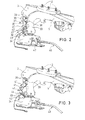
- in einer perspektivischen Draufsicht in vergrößerter Teildarstellung die Trägereinrichtung der
Fig. 1 ; - Fig. 3
- in einer Ansicht gemäß
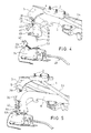
Fig. 2 die von der Karosserie entriegelte Trägereinrichtung; - Fig. 4
- in einer Ansicht gemäß
Fig. 2 die von der Karosserie entriegelte und angehobene Trägereinrichtung; - Fig. 5
- in einer Ansicht gemäß
Fig. 2 die an der Karosserie verriegelte Trägereinrichtung mit dem entriegelten und hochgeschwenkten Verdeckkastendeckel; - Fig. 6
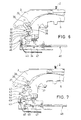
- in einer Seitenansicht den Vorderabschnitt der an der Karosserie verriegelten Trägereinrichtung und die entriegelte Halterung des Verdeckkastendeckels;
- Fig. 7
- in einer Seitenansicht gemäß
Fig. 6 den Vorderabschnitt der von der Karosserie entriegelten Trägereinrichtung und die verriegelte Halterung des Verdeckkastendeckels; - Fig. 8
- in einer Seitenansicht gemäß
Fig. 6 die Verriegelungsvorrichtung in einer Umschaltstellung; - Fig. 9
- in einer Seitenansicht gemäß
Fig. 6 die Verriegelungsvorrichtung in einer Riegelstellung der Trägerreinrichtung bei geöffnetem Verdeckkastendeckels; - Fig. 10
- in einer perspektivischen Draufsicht in vergrößerter Teildarstellung die Antriebseinrichtung der Trägereinrichtung und der Verriegelungsvorrichtung in einer Stellung gemäß
Fig. 1 ; - Fig. 11
- in einer perspektivischen Draufsicht in vergrößerter Teildarstellung die Antriebseinrichtung der Trägereinrichtung und der Verriegelungsvorrichtung in einer Stellung gemäß den
Fig. 3 und7 ; und - Fig. 12
- in einer perspektivischen Draufsicht in vergrößerter Teildarstellung die Antriebseinrichtung in einer Riegelstellung bei hochgeschwenkter Trägereinrichtung.
- Fig. 1
- in a perspective plan view of a right-side support means of a convertible top compartment cover of a convertible, which is arranged in the closed position and locked by means of a locking device on the body;
- Fig. 2
- in a perspective plan view in an enlarged partial view, the support means of
Fig. 1 ; - Fig. 3
- in a view according to
Fig. 2 the carrier unlocked from the body; - Fig. 4
- in a view according to
Fig. 2 the vehicle body unlocked and raised support means; - Fig. 5
- in a view according to
Fig. 2 the locked to the body support means with the unlocked and swung-top compartment lid; - Fig. 6
- in a side view of the front portion of the locked to the body support means and the unlocked mounting of the top compartment lid;
- Fig. 7
- in a side view according to
Fig. 6 the front portion of the unlocked from the body support means and the locked support of the top compartment lid; - Fig. 8
- in a side view according to
Fig. 6 the locking device in a switched position; - Fig. 9
- in a side view according to
Fig. 6 the locking device in a locking position of the carrier device with open top compartment lid; - Fig. 10
- in a perspective plan view in an enlarged partial view of the drive means of the support means and the locking device in a position according to
Fig. 1 ; - Fig. 11
- in a perspective plan view in an enlarged partial view of the drive means of the support means and the locking device in a position according to the
Fig. 3 and7 ; and - Fig. 12
- in a perspective plan view in an enlarged partial view of the drive device in a locked position with pivoted support means.
Ein Cabriolet weist einen Verdeckkastendeckel 1 auf (der Verdeckkastendeckel 1 ist nur in
Der Verdeckkastendeckel 1 ist beidseitig mittels einer jeweiligen Halterung, die z. B. mehrere Schraubenbolzen 2 enthält, an einer Konsole 3 befestigt, die wiederum über ein von zwei Lenkern 4 und 5 gebildetes Viergelenk an einer Trägereinrichtung schwenkbar gelagert, die z. B. von einem Rahmen 6 gebildet ist, der die Konsole 3 bzw. das Viergelenk 4, 5 lagert. Die Beschreibung erfolgt anhand der rechten Seite der im wesentlichen symmetrisch zur Fahrzeuglängsachse gebauten Trägereinrichtung des Verdeckkastendeckels mit der jeweiligen Antriebseinrichtung und Verriegelungsvorrichtung.The
Der linksseitige und der rechtsseitige Rahmen 6 können miteinander z.B. mittels einer Querstange oder dergleichen fest verbunden sein, um die Stabilität der Trägereinrichtung zu erhöhen.The left-side and the right-
Die Trägereinrichtung bzw. der Rahmen 6 des Verdeckkastendeckels 1 ist beidseits an der Karosserie jeweils mittels eines Hauptlenkers 7 und eines Hilfslenkers 8, die ein Viergelenk mit den Gelenken 9 bzw. 10 am Rahmen 6 und den Gelenken 11 bzw. 12 an einer karosseriefesten Lagerplatte 13 bilden, schwenkbar gelagert.The support means or the
Der Hauptlenker 7 weist eine sich über das eine Schwenk- oder Lagerachse bildende Gelenk 11 hinaus erstreckende Verlängerung 14 auf, an der endseitig in einem Gelenk 15 eine Verbindungsstange 16 angelenkt ist, die andererseits in einem Gelenk 17 an einem Arm 18 eines zweiarmigen Schwenkhebels 19 angelenkt ist, der um eine Schwenkachse 20 an der Lagerplatte 13 schwenkbar gelagert ist. Am zweiten Arm 21 des zweiarmigen Schwenkhebels 19 greift in einem Anlenkpunkt 22 eine Antriebseinheit an, die z. B. von einer hydraulischen Kolben-Zylinder-Einheit 23 gebildet ist.The
Die Kolben-Zylinder-Einheit 23 ist andererseits über einen Lagerstift 24 an zwei Langlochführungen 25 verschiebbar gelagert, die in der Lagerplatte 13 bzw. einer daran parallel angebrachten Stützplatte 26 angeordnet sind. Eine doppelte Drehfalle 27 (siehe
Eine Riegeleinrichtung für den Verdeckkastendeckel 1 enthält eine erste Schloßeinheit 32 (siehe auch
Die zweite Schloßeinheit 35 enthält einen Schloßhaken 36, der am Vorderende 33 des Rahmens 6 um eine Querachse 37 schwenkbar gelagert und mittels einer Drehfeder 38 in eine Schließstellung vorgespannt ist (
Die erste Schloßeinheit 32 weist einen an der karosseriefesten Lagereinheit 34 um eine Achse 43 schwenkbar gelagerten Riegelhaken 44 auf, an dem der Betätigungsstift 42 zum Betätigen der zweiten Schloßeinheit 35 angebracht ist und an dessen sich zur Schwenkachse 43 gegenüberliegend erstreckenden Betätigungsarm 45 in einem Langloch 46 ein Kabel 47 eines Bowdenzugs 48 befestigt ist, dessen anderes Ende an dem Lagerstift 24 der Kolben-Zylinder-Einheit 23 angebracht ist. Der geschlossene Riegelhaken 44 hintergreift einen Riegelzapfen 49, der am Vorderende 33 des Rahmens 6 in etwa unterhalb der Schwenkachse 37 des Schloßhakens 36 der zweiten Schloßeinheit 35 angebracht ist.The
In der in den
Wenn das Dach geöffnet und in den Verdeckkasten abgelegt werden soll, wird zuvor der Verdeckkastendeckel 1 angehoben, so dass der Bewegungsweg zum Ablegen des Daches (wie auch zum Ausfahren beim Schließen des Daches) freigelegt wird. Dazu wird die Kolben-Zylinder-Einheit 23 betätigt, die bei ihrer anfänglichen Expansionsbewegung aus der in
Beim Entriegeln der ersten Schloßeinheit 32 schwenkt der Betätigungsstift 42 des Riegelhakens 44 den Schloßhaken 36 der zweiten Schloßeinheit 35 in seine Schließstellung, in der er den Zapfen 39 der Konsole 3 verriegelt hält und gleichzeitig durch die Kraft der Drehfeder 38 gehalten wird (
Das Anheben des Rahmens 6 und damit des Verdeckkastendeckels 1 erfolgt mittels der weiterhin betätigten Kolben-Zylinder-Einheit 23, die nun mit ihrem Unterende bzw. dem Lagerstift 24 am unteren Ende der Langlochführung 25 abgestützt ist und demgemäß durch Expansion der Kolbenstange 51 den Schwenkhebel 19 verschwenkt, wodurch über die Kopplung der Verbindungsstange 16 mit dem Hauptlenker 7 der Rahmen 6 in die angehobene Offenstellung verschwenkt wird (über die Stellung der
Bei angehobenem Rahmen 6 und mit dem Rahmen 6 angehobenem Verdeckkastendeckel 1 kann das Dach in bekannter Weise in den Verdeckkasten oder Dachablageraum bewegt und, zum Schließen des Daches, auch wieder herausbewegt werden.With raised
Das Schließen des Verdeckkastendeckels 1 bzw. des Rahmens 6 erfolgt in entgegengesetztem Bewegungsablauf durch Einfahren der Kolbenstange 51 der Kolben-Zylinder-Einheit 23 aus der Stellung gemäß
Wenn der Rahmen 6 mit seinem Vorderende 33 in seine Schließstellung auf der Lagereinheit 34 bewegt ist und mit einer Zentriernase 52 in einer Zentrieraufnahme 53 der Lagereinheit 34 aufgenommen ist, hat auch die Drehfalle 27 über die Ansteuerung des Steuerlenkers 29 ihre Offenstellung eingenommen, so dass die weitere Betätigung bzw. Verkürzung der Kolben-Zylinder-Einheit 23 auf dem letzten Verstellweg dazu führt, dass sich das Unterende des Gehäuses 50 bzw. der Lagerstift 24 an der Langlochführung 25 nach oben in die entgegengesetzte Endstellung bewegt. Dabei wird über das Kabel 47 des Bowdenzugs 48 der Riegelhaken 44 der ersten Schloßeinheit 32 betätigt, der beim Verschwenken in seine Schließstellung den Riegelzapfen 49 greift und damit die Trägereinrichtung bzw. den Rahmen 6 nach unten in eine feste Riegelverbindung an der Karosserie zieht.When the
Der Bowdenzug 48 als Teil der Betätigungseinrichtung kann weitgehend flexibel an die baulichen Gegebenheiten im Heckbereich der Karosserie angepasst werden. Jedoch können auch andere Mittel wie z. B. Gestänge zur Übertragung der Betätigungsbewegung verwendet werden.The
Der Verdeckkastendeckel 1 kann durch eine.jeweilige Gasdruckfeder 54 gegenüber dem Rahmen 6 abgestützt sein, so dass er beim manuellen Verschwenken in seiner Funktion als Kofferraumdeckel gewichtsentlastet ist.
Claims (16)
- Locking mechanism for securing a support device of a folding top compartment cover of a convertible, which support device is mounted movably on the vehicle body by means of a driving device,
characterized by
a first lock unit (32), which is mounted on the vehicle body, for releasably locking the support device (6) to the vehicle body (34),
a second lock unit (35), which is mounted on the support device (6), for releasably locking the folding top compartment cover (1), which is mounted movably on the support device (6), to the support device (6), and an actuating device (42, 48) for actuating the two lock units (32, 35). - Locking mechanism according to Claim 1,
characterized in that the actuating device (42, 48) is connected to the driving device (23). - Locking mechanism according to Claim 1 or 2,
characterized in that the two lock units (32, 35) are arranged adjacent to each other. - Locking mechanism according to one of Claims 1 to 3,
characterized in that, when the second lock unit (35) is actuated, the first lock unit (32) is connected thereto in a releasable coupling engagement. - Locking mechanism according to one of Claims 1 to 4,
characterized in that a latching hook (44) of the first lock unit (32) and a lock hook (36) of the second lock unit (35) can be coupled to each other via engagement elements. - Locking mechanism according to Claim 5,
characterized in that an actuating pin (42) and a slotted guide (41) which receives the actuating pin (42) form the engagement elements. - Locking mechanism according to one of Claims 1 to 6,
characterized in that, in a closed position, the support device (6) is kept locked to the vehicle body (34) by means of the first lock unit (32), with the second lock unit (35) having released the folding top compartment cover (1) from the support device (6). - Locking mechanism according to one of Claims 1 to 7,
characterized in that the actuating device (42, 48), which is formed in particular as a Bowden cable (47, 48), is connected to a latching hook (44) of the first lock unit (32). - Locking mechanism according to one of Claims 1 to 8,
characterized in that a lock hook (36) of the second lock unit (35) is prestressed by means of a prestressing device (38) into its closed position in which it keeps the folding top compartment cover (1) or a bearing part (3) of the folding top compartment cover (1) locked to the support device (6). - Locking mechanism according to one of Claims 1 to 9,
characterized in that the folding top compartment cover (1) is attached by means of a mount (2) to a bracket (3) which is mounted movably on the support device (6) by means of a link device (4, 5). - Locking mechanism according to one of Claims 1 to 10,
characterized in that the driving device (23) is guided displaceably at its end coupled to the actuating device (47, 48) along a guide (25) and can be locked by means of a retaining device (27, 29) in an end position in which the first lock unit (32) is unlocked. - Locking mechanism according to one of Claims 1 to 11,
characterized in that the retaining device (27, 29) can be actuated by a lever (19), which is movable by the driving device (23), for driving the support device (6). - Locking mechanism according to one of Claims 1 to 12,
characterized in that the support device (6) is supported on the vehicle by means of a main link (7), in particular in a four-bar linkage arrangement. - Locking mechanism according to one of Claims 1 to 13,
characterized in that, in the closed position, the support device (6) is supported in a manner mounted on the vehicle by means of a centering receptacle. - Locking mechanism according to one of Claims 1 to 14,
characterized in that the support device is a frame (6) which is supported movably on the vehicle body via an articulated device, in particular a four- or multi-bar linkage mechanism (7 and 8), and the folding top compartment cover (1) is mounted pivotably on said frame. - Locking mechanism according to one of Claims 1 to 15,
characterized in that the driving unit is a linear adjustment unit and, in particular, is a hydraulic piston/cylinder unit (23).
Applications Claiming Priority (2)
| Application Number | Priority Date | Filing Date | Title |
|---|---|---|---|
| DE102005052063A DE102005052063A1 (en) | 2005-10-28 | 2005-10-28 | Locking device of a convertible top compartment cover of a convertible |
| PCT/DE2006/001906 WO2007048402A1 (en) | 2005-10-28 | 2006-10-27 | Locking mechanism for a folding top compartment cover of a convertible |
Publications (2)
| Publication Number | Publication Date |
|---|---|
| EP1940640A1 EP1940640A1 (en) | 2008-07-09 |
| EP1940640B1 true EP1940640B1 (en) | 2015-12-23 |
Family
ID=37775312
Family Applications (1)
| Application Number | Title | Priority Date | Filing Date |
|---|---|---|---|
| EP06818031.4A Not-in-force EP1940640B1 (en) | 2005-10-28 | 2006-10-27 | Locking mechanism for a folding top compartment cover of a convertible |
Country Status (5)
| Country | Link |
|---|---|
| US (1) | US20080277975A1 (en) |
| EP (1) | EP1940640B1 (en) |
| JP (1) | JP2009513425A (en) |
| DE (1) | DE102005052063A1 (en) |
| WO (1) | WO2007048402A1 (en) |
Families Citing this family (6)
| Publication number | Priority date | Publication date | Assignee | Title |
|---|---|---|---|---|
| DE102009050497A1 (en) | 2009-10-23 | 2011-04-28 | Dr. Ing. H.C. F. Porsche Aktiengesellschaft | Device for locking and unlocking a top compartment lid |
| DE102010008119A1 (en) * | 2010-02-16 | 2011-08-18 | Magna Car Top Systems GmbH, 74321 | Closure for a cover |
| DE102012108531B4 (en) * | 2012-09-12 | 2019-01-24 | Webasto-Edscha Cabrio GmbH | Convertible top with locking unit |
| JP6225929B2 (en) * | 2015-02-16 | 2017-11-08 | マツダ株式会社 | Rear body structure of the vehicle |
| EP3388267B1 (en) * | 2017-04-12 | 2021-06-02 | Webasto SE | Closure device with closing hook and carriage that can be displaced on a shutter holder |
| DE102017118153A1 (en) * | 2017-08-09 | 2019-02-14 | Webasto SE | Cabriolet arrangement with locking device for top compartment lid |
Family Cites Families (16)
| Publication number | Priority date | Publication date | Assignee | Title |
|---|---|---|---|---|
| DE4123516C1 (en) * | 1991-07-16 | 1992-07-09 | Mercedes-Benz Aktiengesellschaft, 7000 Stuttgart, De | |
| DE4445944C1 (en) * | 1994-12-22 | 1996-04-25 | Daimler Benz Ag | Hard top motor car |
| DE19507431C1 (en) * | 1995-03-03 | 1996-08-01 | Daimler Benz Ag | Hardtop vehicle |
| DE19516876C1 (en) * | 1995-05-09 | 1996-11-28 | Daimler Benz Ag | Drive arrangement for moving a lockable vehicle part |
| DE19756062C1 (en) * | 1997-12-17 | 1999-04-01 | Daimler Benz Ag | Cabriolet motor vehicle hood |
| DE19932501C2 (en) * | 1999-07-12 | 2001-07-05 | Webasto Vehicle Sys Int Gmbh | Mechanism for a swiveling tailgate |
| DE29916003U1 (en) * | 1999-09-13 | 2001-03-15 | Karmann Gmbh W | Cabriolet vehicle |
| JP4453147B2 (en) * | 2000-02-25 | 2010-04-21 | アイシン精機株式会社 | VEHICLE ROOF LOCK DEVICE AND ITS OPERATION CONTROL DEVICE |
| DE10038530B4 (en) * | 2000-08-08 | 2011-02-24 | Wilhelm Karmann Gmbh | Cabriolet vehicle with a can be placed under a cover part roof |
| DE10107079B4 (en) * | 2001-02-13 | 2008-03-20 | Webasto Ag | Top compartment lid for a convertible |
| US6520557B2 (en) * | 2001-06-05 | 2003-02-18 | Delphi Technologies, Inc. | Power actuating system for four-bar hinge articulated vehicle closure element field of the invention |
| FR2834487B1 (en) * | 2002-01-04 | 2004-02-20 | France Design | DEVICE FOR OPENING AND CLOSING THE COVER OF THE REAR TRUNK OF A DISCOVERABLE VEHICLE WITH FOLDABLE ROOF |
| DE10213337B4 (en) * | 2002-03-25 | 2004-09-09 | Cts Fahrzeug-Dachsysteme Gmbh | Trunk lid for a convertible vehicle |
| US6837535B2 (en) * | 2002-08-15 | 2005-01-04 | Asc Incorporated | Convertible roof system |
| DE10249299B4 (en) * | 2002-10-22 | 2009-10-15 | Webasto Ag | Storage compartment cover of a convertible |
| US7124650B2 (en) * | 2004-04-06 | 2006-10-24 | Ford Global Technologies, Llc | Method and system for determining automotive convertible top operating characteristics |
-
2005
- 2005-10-28 DE DE102005052063A patent/DE102005052063A1/en not_active Withdrawn
-
2006
- 2006-10-23 US US12/091,716 patent/US20080277975A1/en not_active Abandoned
- 2006-10-27 WO PCT/DE2006/001906 patent/WO2007048402A1/en active Application Filing
- 2006-10-27 JP JP2008536927A patent/JP2009513425A/en not_active Withdrawn
- 2006-10-27 EP EP06818031.4A patent/EP1940640B1/en not_active Not-in-force
Also Published As
| Publication number | Publication date |
|---|---|
| US20080277975A1 (en) | 2008-11-13 |
| WO2007048402A1 (en) | 2007-05-03 |
| DE102005052063A1 (en) | 2007-05-03 |
| EP1940640A1 (en) | 2008-07-09 |
| JP2009513425A (en) | 2009-04-02 |
Similar Documents
| Publication | Publication Date | Title |
|---|---|---|
| EP1839922B1 (en) | Convertible vehicle roof | |
| EP1907230B1 (en) | Supporting device for a soft top compartment cover of a convertible | |
| DE10059342C5 (en) | Convertible vehicle roof | |
| EP1199202A2 (en) | Convertible vehicle with a roof storable beneath a cover element on the rear part of the vehicle | |
| DE102005033609B4 (en) | Drive device of a movable component of a vehicle | |
| EP1940640B1 (en) | Locking mechanism for a folding top compartment cover of a convertible | |
| EP1658188B1 (en) | Bootlid for a cabriolet vehicle | |
| DE102005043511A1 (en) | Cabriolet vehicle with retractable in a top compartment vehicle roof | |
| EP1588884B1 (en) | Collapsible top of a vehicle | |
| DE102005060206B4 (en) | Drive device of a movable component of a vehicle | |
| EP1915268A1 (en) | Folding top for a convertible | |
| DE10249299B4 (en) | Storage compartment cover of a convertible | |
| DE102004005882B4 (en) | Folding top for motor vehicle e.g. cabriolet, has main and auxiliary units coupled with each other for common operation so that auxiliary unit operates locking mechanism for releasing bolting device before moving bearing device by main unit | |
| DE10337353B4 (en) | Convertible car | |
| EP2098398A2 (en) | Soft top for a convertible | |
| DE102006042720B4 (en) | Hard top folding roof of a convertible | |
| EP2061667B1 (en) | Retractable hardtop | |
| EP2383135B1 (en) | Movable cover | |
| EP1798090B1 (en) | Rear shelf for cabriolet | |
| DE102020121341A1 (en) | Convertible top compartment lid arrangement with link arrangement and lock arrangement | |
| DE102006042718B4 (en) | Vehicle with a folding roof |
Legal Events
| Date | Code | Title | Description |
|---|---|---|---|
| PUAI | Public reference made under article 153(3) epc to a published international application that has entered the european phase |
Free format text: ORIGINAL CODE: 0009012 |
|
| 17P | Request for examination filed |
Effective date: 20080508 |
|
| AK | Designated contracting states |
Kind code of ref document: A1 Designated state(s): AT BE BG CH CY CZ DE DK EE ES FI FR GB GR HU IE IS IT LI LT LU LV MC NL PL PT RO SE SI SK TR |
|
| 17Q | First examination report despatched |
Effective date: 20110203 |
|
| DAX | Request for extension of the european patent (deleted) | ||
| GRAP | Despatch of communication of intention to grant a patent |
Free format text: ORIGINAL CODE: EPIDOSNIGR1 |
|
| INTG | Intention to grant announced |
Effective date: 20150428 |
|
| GRAS | Grant fee paid |
Free format text: ORIGINAL CODE: EPIDOSNIGR3 |
|
| GRAP | Despatch of communication of intention to grant a patent |
Free format text: ORIGINAL CODE: EPIDOSNIGR1 |
|
| INTG | Intention to grant announced |
Effective date: 20151008 |
|
| RAP1 | Party data changed (applicant data changed or rights of an application transferred) |
Owner name: WEBASTO SE |
|
| GRAA | (expected) grant |
Free format text: ORIGINAL CODE: 0009210 |
|
| AK | Designated contracting states |
Kind code of ref document: B1 Designated state(s): AT BE BG CH CY CZ DE DK EE ES FI FR GB GR HU IE IS IT LI LT LU LV MC NL PL PT RO SE SI SK TR |
|
| REG | Reference to a national code |
Ref country code: GB Ref legal event code: FG4D Free format text: NOT ENGLISH |
|
| REG | Reference to a national code |
Ref country code: CH Ref legal event code: EP |
|
| REG | Reference to a national code |
Ref country code: IE Ref legal event code: FG4D Free format text: LANGUAGE OF EP DOCUMENT: GERMAN |
|
| REG | Reference to a national code |
Ref country code: AT Ref legal event code: REF Ref document number: 766385 Country of ref document: AT Kind code of ref document: T Effective date: 20160115 |
|
| REG | Reference to a national code |
Ref country code: DE Ref legal event code: R096 Ref document number: 502006014688 Country of ref document: DE |
|
| REG | Reference to a national code |
Ref country code: LT Ref legal event code: MG4D |
|
| REG | Reference to a national code |
Ref country code: NL Ref legal event code: MP Effective date: 20151223 |
|
| PG25 | Lapsed in a contracting state [announced via postgrant information from national office to epo] |
Ref country code: LT Free format text: LAPSE BECAUSE OF FAILURE TO SUBMIT A TRANSLATION OF THE DESCRIPTION OR TO PAY THE FEE WITHIN THE PRESCRIBED TIME-LIMIT Effective date: 20151223 |
|
| PG25 | Lapsed in a contracting state [announced via postgrant information from national office to epo] |
Ref country code: FI Free format text: LAPSE BECAUSE OF FAILURE TO SUBMIT A TRANSLATION OF THE DESCRIPTION OR TO PAY THE FEE WITHIN THE PRESCRIBED TIME-LIMIT Effective date: 20151223 Ref country code: LV Free format text: LAPSE BECAUSE OF FAILURE TO SUBMIT A TRANSLATION OF THE DESCRIPTION OR TO PAY THE FEE WITHIN THE PRESCRIBED TIME-LIMIT Effective date: 20151223 Ref country code: SE Free format text: LAPSE BECAUSE OF FAILURE TO SUBMIT A TRANSLATION OF THE DESCRIPTION OR TO PAY THE FEE WITHIN THE PRESCRIBED TIME-LIMIT Effective date: 20151223 Ref country code: GR Free format text: LAPSE BECAUSE OF FAILURE TO SUBMIT A TRANSLATION OF THE DESCRIPTION OR TO PAY THE FEE WITHIN THE PRESCRIBED TIME-LIMIT Effective date: 20160324 Ref country code: NL Free format text: LAPSE BECAUSE OF FAILURE TO SUBMIT A TRANSLATION OF THE DESCRIPTION OR TO PAY THE FEE WITHIN THE PRESCRIBED TIME-LIMIT Effective date: 20151223 |
|
| PG25 | Lapsed in a contracting state [announced via postgrant information from national office to epo] |
Ref country code: ES Free format text: LAPSE BECAUSE OF FAILURE TO SUBMIT A TRANSLATION OF THE DESCRIPTION OR TO PAY THE FEE WITHIN THE PRESCRIBED TIME-LIMIT Effective date: 20151223 Ref country code: CZ Free format text: LAPSE BECAUSE OF FAILURE TO SUBMIT A TRANSLATION OF THE DESCRIPTION OR TO PAY THE FEE WITHIN THE PRESCRIBED TIME-LIMIT Effective date: 20151223 Ref country code: IT Free format text: LAPSE BECAUSE OF FAILURE TO SUBMIT A TRANSLATION OF THE DESCRIPTION OR TO PAY THE FEE WITHIN THE PRESCRIBED TIME-LIMIT Effective date: 20151223 |
|
| PG25 | Lapsed in a contracting state [announced via postgrant information from national office to epo] |
Ref country code: PT Free format text: LAPSE BECAUSE OF FAILURE TO SUBMIT A TRANSLATION OF THE DESCRIPTION OR TO PAY THE FEE WITHIN THE PRESCRIBED TIME-LIMIT Effective date: 20160426 Ref country code: IS Free format text: LAPSE BECAUSE OF FAILURE TO SUBMIT A TRANSLATION OF THE DESCRIPTION OR TO PAY THE FEE WITHIN THE PRESCRIBED TIME-LIMIT Effective date: 20160423 Ref country code: PL Free format text: LAPSE BECAUSE OF FAILURE TO SUBMIT A TRANSLATION OF THE DESCRIPTION OR TO PAY THE FEE WITHIN THE PRESCRIBED TIME-LIMIT Effective date: 20151223 Ref country code: EE Free format text: LAPSE BECAUSE OF FAILURE TO SUBMIT A TRANSLATION OF THE DESCRIPTION OR TO PAY THE FEE WITHIN THE PRESCRIBED TIME-LIMIT Effective date: 20151223 Ref country code: RO Free format text: LAPSE BECAUSE OF FAILURE TO SUBMIT A TRANSLATION OF THE DESCRIPTION OR TO PAY THE FEE WITHIN THE PRESCRIBED TIME-LIMIT Effective date: 20151223 Ref country code: SK Free format text: LAPSE BECAUSE OF FAILURE TO SUBMIT A TRANSLATION OF THE DESCRIPTION OR TO PAY THE FEE WITHIN THE PRESCRIBED TIME-LIMIT Effective date: 20151223 |
|
| REG | Reference to a national code |
Ref country code: DE Ref legal event code: R097 Ref document number: 502006014688 Country of ref document: DE |
|
| REG | Reference to a national code |
Ref country code: FR Ref legal event code: PLFP Year of fee payment: 11 |
|
| PLBE | No opposition filed within time limit |
Free format text: ORIGINAL CODE: 0009261 |
|
| STAA | Information on the status of an ep patent application or granted ep patent |
Free format text: STATUS: NO OPPOSITION FILED WITHIN TIME LIMIT |
|
| PG25 | Lapsed in a contracting state [announced via postgrant information from national office to epo] |
Ref country code: DK Free format text: LAPSE BECAUSE OF FAILURE TO SUBMIT A TRANSLATION OF THE DESCRIPTION OR TO PAY THE FEE WITHIN THE PRESCRIBED TIME-LIMIT Effective date: 20151223 |
|
| 26N | No opposition filed |
Effective date: 20160926 |
|
| PG25 | Lapsed in a contracting state [announced via postgrant information from national office to epo] |
Ref country code: SI Free format text: LAPSE BECAUSE OF FAILURE TO SUBMIT A TRANSLATION OF THE DESCRIPTION OR TO PAY THE FEE WITHIN THE PRESCRIBED TIME-LIMIT Effective date: 20151223 Ref country code: BE Free format text: LAPSE BECAUSE OF NON-PAYMENT OF DUE FEES Effective date: 20161031 |
|
| REG | Reference to a national code |
Ref country code: CH Ref legal event code: PL |
|
| REG | Reference to a national code |
Ref country code: IE Ref legal event code: MM4A |
|
| PG25 | Lapsed in a contracting state [announced via postgrant information from national office to epo] |
Ref country code: LI Free format text: LAPSE BECAUSE OF NON-PAYMENT OF DUE FEES Effective date: 20161031 Ref country code: CH Free format text: LAPSE BECAUSE OF NON-PAYMENT OF DUE FEES Effective date: 20161031 |
|
| PG25 | Lapsed in a contracting state [announced via postgrant information from national office to epo] |
Ref country code: LU Free format text: LAPSE BECAUSE OF NON-PAYMENT OF DUE FEES Effective date: 20161027 |
|
| REG | Reference to a national code |
Ref country code: FR Ref legal event code: PLFP Year of fee payment: 12 |
|
| PG25 | Lapsed in a contracting state [announced via postgrant information from national office to epo] |
Ref country code: IE Free format text: LAPSE BECAUSE OF NON-PAYMENT OF DUE FEES Effective date: 20161027 |
|
| REG | Reference to a national code |
Ref country code: BE Ref legal event code: MM Effective date: 20161031 |
|
| REG | Reference to a national code |
Ref country code: AT Ref legal event code: MM01 Ref document number: 766385 Country of ref document: AT Kind code of ref document: T Effective date: 20161027 |
|
| PG25 | Lapsed in a contracting state [announced via postgrant information from national office to epo] |
Ref country code: AT Free format text: LAPSE BECAUSE OF NON-PAYMENT OF DUE FEES Effective date: 20161027 |
|
| PGFP | Annual fee paid to national office [announced via postgrant information from national office to epo] |
Ref country code: FR Payment date: 20171023 Year of fee payment: 12 |
|
| PGFP | Annual fee paid to national office [announced via postgrant information from national office to epo] |
Ref country code: GB Payment date: 20171024 Year of fee payment: 12 |
|
| PG25 | Lapsed in a contracting state [announced via postgrant information from national office to epo] |
Ref country code: CY Free format text: LAPSE BECAUSE OF FAILURE TO SUBMIT A TRANSLATION OF THE DESCRIPTION OR TO PAY THE FEE WITHIN THE PRESCRIBED TIME-LIMIT Effective date: 20151223 Ref country code: HU Free format text: LAPSE BECAUSE OF FAILURE TO SUBMIT A TRANSLATION OF THE DESCRIPTION OR TO PAY THE FEE WITHIN THE PRESCRIBED TIME-LIMIT; INVALID AB INITIO Effective date: 20061027 |
|
| PG25 | Lapsed in a contracting state [announced via postgrant information from national office to epo] |
Ref country code: MC Free format text: LAPSE BECAUSE OF FAILURE TO SUBMIT A TRANSLATION OF THE DESCRIPTION OR TO PAY THE FEE WITHIN THE PRESCRIBED TIME-LIMIT Effective date: 20151223 Ref country code: TR Free format text: LAPSE BECAUSE OF FAILURE TO SUBMIT A TRANSLATION OF THE DESCRIPTION OR TO PAY THE FEE WITHIN THE PRESCRIBED TIME-LIMIT Effective date: 20151223 |
|
| PG25 | Lapsed in a contracting state [announced via postgrant information from national office to epo] |
Ref country code: BG Free format text: LAPSE BECAUSE OF FAILURE TO SUBMIT A TRANSLATION OF THE DESCRIPTION OR TO PAY THE FEE WITHIN THE PRESCRIBED TIME-LIMIT Effective date: 20151223 |
|
| GBPC | Gb: european patent ceased through non-payment of renewal fee |
Effective date: 20181027 |
|
| PG25 | Lapsed in a contracting state [announced via postgrant information from national office to epo] |
Ref country code: FR Free format text: LAPSE BECAUSE OF NON-PAYMENT OF DUE FEES Effective date: 20181031 |
|
| PG25 | Lapsed in a contracting state [announced via postgrant information from national office to epo] |
Ref country code: GB Free format text: LAPSE BECAUSE OF NON-PAYMENT OF DUE FEES Effective date: 20181027 |
|
| PGFP | Annual fee paid to national office [announced via postgrant information from national office to epo] |
Ref country code: DE Payment date: 20191023 Year of fee payment: 14 |
|
| REG | Reference to a national code |
Ref country code: DE Ref legal event code: R119 Ref document number: 502006014688 Country of ref document: DE |
|
| PG25 | Lapsed in a contracting state [announced via postgrant information from national office to epo] |
Ref country code: DE Free format text: LAPSE BECAUSE OF NON-PAYMENT OF DUE FEES Effective date: 20210501 |