EP1197866A2 - Programmgesteuerte Einheit - Google Patents
Programmgesteuerte Einheit Download PDFInfo
- Publication number
- EP1197866A2 EP1197866A2 EP01123997A EP01123997A EP1197866A2 EP 1197866 A2 EP1197866 A2 EP 1197866A2 EP 01123997 A EP01123997 A EP 01123997A EP 01123997 A EP01123997 A EP 01123997A EP 1197866 A2 EP1197866 A2 EP 1197866A2
- Authority
- EP
- European Patent Office
- Prior art keywords
- program
- controlled unit
- program execution
- stopped
- units
- Prior art date
- Legal status (The legal status is an assumption and is not a legal conclusion. Google has not performed a legal analysis and makes no representation as to the accuracy of the status listed.)
- Granted
Links
Images
Classifications
-
- G—PHYSICS
- G06—COMPUTING OR CALCULATING; COUNTING
- G06F—ELECTRIC DIGITAL DATA PROCESSING
- G06F11/00—Error detection; Error correction; Monitoring
- G06F11/36—Prevention of errors by analysis, debugging or testing of software
- G06F11/362—Debugging of software
- G06F11/3648—Debugging of software using additional hardware
Definitions
- the present invention relates to a device according to the Preamble of claim 1, i.e. a program-controlled Unit with one or more program execution units to execute a program, where at least one of the program execution units Stopping device is assigned, through which the Program execution by the program execution unit, the the stopping device is assigned to be stopped can.
- Program-controlled units of this type are, for example Microprocessors, microcontrollers, signal processors etc.
- the stopping facility through which the program execution by a program execution unit executing a program the program-controlled unit are stopped can be, for example, a so-called on-chip debug support or OCDS module.
- OCDS modules have the ability to determine the occurrence of certain Events (breakpoints), for example access to a specific address in the program memory or in the data memory, the execution of a specific command, the reading or Writing certain data from or into a memory, too monitor, and in response to the occurrence of the event the program execution by the program execution unit, which it is assigned to stop.
- breakpoints for example access to a specific address in the program memory or in the data memory, the execution of a specific command, the reading or Writing certain data from or into a memory, too monitor, and in response to the occurrence of the event the program execution by the program execution unit, which it is assigned to stop.
- an external Debugger the stopped programmable unit and / or the system containing this for possible causes of a investigate improper function and / or - for example by changing register contents - in put a certain state.
- the present invention is therefore based on the object the program-controlled unit according to the preamble of Develop claim 1 such that this at least then when in it while stopping the program execution none or in any case not undone Manipulations have occurred while continuing the Program execution continues in exactly the same way under all circumstances as she would have done if the program execution had not stopped would have been.
- Draw the program-controlled units according to the invention are characterized in that the stopping device can that in addition to the program execution unit which it is assigned to other components of the program-controlled Unit are stopped.
- the program-controlled unit is the one under consideration Example of a microcontroller. However, it is already pointed out at this point that this there is no restriction; those described below Special features of the program-controlled unit can also come with any other program-controlled use.
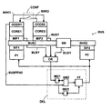
- the first program execution unit CORE1 and the second Program execution unit CORE2 run independently of each other the same or different programs.
- peripheral units P1 and P2 are, for example, A / D converters, Timers, DMA controllers or other units that in program-controlled units next to one or more Program execution units can be used and cooperate with them.
- the Bus Bridge BB is used to connect the bus parts BUS1 and BUS2. Bus bridges are provided to facilitate data transmission disruptive line capacities are kept low can and / or with different speeds and / or differently constructed or working buses or bus parts can be coupled to each other.
- the Bus Bridge BB accepts data from the bus section BUS1 and forwards it to the Bus part BUS2 continues, and conversely takes from bus part BUS2 Data and forwards them to the bus section BUS1; the data to be forwarded are usually in one Buffer buffered.
- the OCDS modules assigned to the program execution units OCDS1 and OCDS2 enable the program execution units, to which they are assigned by a to debug external debugger.
- OCDS modules OCDS1 and OCDS2 are as Stop device for stopping the program execution the program execution unit to which they are assigned, can be used; the OCDS modules have the ability the occurrence of certain events (breakpoints) in the program execution units to which they are assigned for example access to a specific address in the program memory or in data storage, the execution of a particular Command, the reading or registration of certain Monitor data from or into a memory, and in response on the occurrence of the event the program execution through the program execution unit which it are assigned to stop. There is no difference to conventional OCDS modules.
- OCDS modules OCDS1 and Stop devices formed by OCDS2 also point out the property on that they can cause that alongside the program execution unit to which it is assigned are other components of the program-controlled Unit are stopped.
- Stopping the second program execution unit CORE2 by the first OCDS module OCDS1 is done by a signal BRK1, which connects the first OCDS module OCDS1 to the second OCDS module Outputs OCDS2, and which the second OCDS module OCDS2 takes the occasion, the second program execution unit CORE2 to stop; stopping the first program execution unit CORE1 through the second OCDS module OCDS2 is done by a signal BRK2, which the second OCDS module OCDS2 to the outputs first OCDS module OCDS1, and which the first OCDS module OCDS1 uses the first program execution unit Stop CORE1.
- the signals BRK1 and BRK2 also directly to the program execution unit can be fed, stopping them should be initiated; this also enables program execution units stopped who have no OCDS module assigned.
- the signals BRK1 and BRK2 pass on their way to the OCDS modules for which they are intended, the stopping configuration device CONF.
- the stopping configuration device CONF contains switching elements, via which adjustable is whether the signal BRK1 to the second OCDS module OCDS2 is passed, and / or whether the signal BRK2 to the first OCDS module OCDS1 is let through.
- This suspend signal is approximately at the time to which the program execution units CORE1 and / or CORE2 are stopped, issued, and the Stop delay device DEL supplied.
- the stopping delay device DEL gives this signal with a certain Delay to peripheral units P1 and P2 continues and thereby stops them; through the delayed forwarding the SUSPEND signal to the peripheral units P1 and P2 these become a certain time after the time halting the program execution units.
- P1 and P2 then take place when it is certain that the components of the program-controlled Units that can be bus masters and the Bus Bridge BB no longer have data to output and / or no longer on already Waiting for requested or still to be requested data.
- the components that can be bus masters are considered in the Example the program execution units CORE1 and CORE2; the remaining units of those connected to the bus BUS Units (the peripheral units P1 and P2) can only Be slaves. Therefore, in the example considered, the first Program execution unit CORE1, the second program execution unit CORE2, and Bus Bridge BB then checked whether they still have data to output and / or already Waiting for requested or still to be requested data.
- the BUSY signals of the first program execution unit CORE1 (and / or the associated interface MIF1), the second program execution unit CORE2 (and / or this assigned interface MIF2), and the bus bridge BB are ORed by an OR gate OR; the output of the OR gate OR becomes the stopping delay device DEL supplied.
Landscapes
- Engineering & Computer Science (AREA)
- Computer Hardware Design (AREA)
- Theoretical Computer Science (AREA)
- Quality & Reliability (AREA)
- Physics & Mathematics (AREA)
- General Engineering & Computer Science (AREA)
- General Physics & Mathematics (AREA)
- Debugging And Monitoring (AREA)
- Programmable Controllers (AREA)
Abstract
Description
- eine erste Programmausführungs-Einheit CORE1,
- ein der ersten Programmausführungs-Einheit CORE1 zugeordnetes On-Chip-Debug-Support- bzw. OCDS-Modul OCDS1,
- eine der ersten Programmausführungs-Einheit CORE1 zugeordnete (Master-)Schnittstelle MIF1 zum Anschluß an einen Bus BUS,
- eine zweite Programmausführungs-Einheit CORE2,
- ein der zweiten Programmausführungs-Einheit CORE2 zugeordnetes On-Chip-Debug-Support- bzw. OCDS-Modul OCDS2,
- eine der zweiten Programmausführungs-Einheit CORE2 zugeordnete (Master-)Schnittstelle MIF2 zum Anschluß an den bereits erwähnten Bus BUS,
- eine erste Peripherie-Einheit P1,
- eine der ersten Peripherie-Einheit P1 zugeordnete (Slave-) Schnittstelle SIF1 zum Anschluß an den bereits erwähnten Bus BUS,
- eine zweite Peripherie-Einheit P2,
- eine der zweiten Peripherie-Einheit P2 zugeordnete (Slave-) Schnittstelle SIF2 zum Anschluß an bereits erwähnten Bus BUS,
- den bereits mehrfach erwähnten Bus BUS, wobei dieser Bus aus einem ersten Bus-Teil BUS1, einem zweiten Bus-Teil BUS2, und einer die Bus-Teile BUS1 und BUS2 miteinander verbindenden Bus Bridge BB,
- eine Anhaltekonfigurationsvorrichtung CONF, und
- eine Anhalteverzögerungsvorrichtung DEL.
- eine oder mehrere Programmausführungs-Einheiten, welchen keine oder eine andere als die das Anhalten der Programmausführung initiierende Anhalte-Einrichtung zugeordnet ist, und
- eine oder mehrere mit den Programmausführungs-Einheiten kooperierende Einheiten der programmgesteuerten Einheit.
- kann das erste OCDS-Modul OCDS1 veranlassen, daß neben der ersten Programmausführungs-Einheit CORE1, welcher es zugeordnet ist, auch die zweite Programmausführungs-Einheit CORE2 sowie die erste Peripherie-Einheit P1 und die zweite Peripherie-Einheit P2 angehalten werden, und
- kann das zweite OCDS-Modul OCDS2 veranlassen, daß neben der zweiten Programmausführungs-Einheit CORE2, welcher es zugeordnet ist, auch die erste Programmausführungs-Einheit CORE1 angehalten wird.
- den Wert 1, wenn die jeweilige Einheit noch Daten auszugeben hat und/oder auf bereits angeforderte oder noch anzufordernde Daten wartet, und
- den Wert 0, wenn die jeweilige Einheit keine Daten auszugeben hat und/oder nicht mehr auf bereits angeforderte oder noch anzufordernde Daten wartet.
- der erste Inverter INV1 das Ausgangssignal des ODER-Gatters OR invertiert,
- der zweite Inverter INV2 das der Anhalteverzögerungsvorrichtung DEL zugeführte SUSPEND-Signal invertiert,
- das UND-Gatter AND das Ausgangssignal des ersten Inverters INV1 und das der Anhalteverzögerungsvorrichtung DEL zugeführte (nicht invertierte) SUSPEND-Signal einer UND-Verknüpfung unterzieht, und
- das Flip-Flop FF durch das Ausgangssignal des UND-Gatters AND gesetzt, durch das Ausgangssignal des zweiten Inverters INV2 zurückgesetzt wird, und das die Peripherie-Einheiten P1 und P2 anhaltende SUSPEND-Signal an diese ausgibt.
- ihr ein Signal SUSPEND = 1 zugeführt wird, und
- alle Signale BUSY der Programmausführungs-Einheiten CORE1 und CORE2 (und/oder der diesen zugeordneten Schnittstellen MIF1 und MIF2) sowie der Bus Bridge BB den Wert 0 aufweisen.
- weil sich dadurch das an das Anhalten der programmgesteuerten Einheit anschließende Debuggen derselben vereinfacht und zuverlässigere Ergebnisse über den aktuellen Zustand der programmgesteuerten Einheit liefert, und
- weil die programmgesteuerte Einheit dadurch in einen Zustand versetzt wird, durch den gewährleistet ist, daß die programmgesteuerte Einheit nach der Aufhebung des Anhalte-Zustandes ordnungsgemäß weiterarbeitet (so weiterarbeitet, wie sie es tun würde, wenn sie nicht angehalten worden wäre).
- zunächst das der Anhalteverzögerungsvorrichtung DEL zugeführte Signal SUSPEND auf den Wert 0 gesetzt, was zur Folge hat daß das Flip-Flop FF zurückgesetzt wird und ein die Peripherie-Einheiten P1 und P2 nicht mehr anhaltendes Signal SUSPEND = 0 aus der Anhalteverzögerungsvorrichtung DEL ausgegeben wird, und
- danach das Anhalten der Programmausführung durch die Programmausführungs-Einheiten aufgehoben wird.
- die programmgesteuerte Einheit mehr oder weniger als zwei Programmausführungs-Einheiten enthält,
- nicht jeder Programmausführungs-Einheit ein OCDS-Modul (eine die zugeordnete Programmausführungs-Einheit anhalten könnende Anhalte-Einrichtung) zugeordnet ist,
- mehreren Programmausführungs-Einheit gemeinsames einziges OCDS-Modul (eine einzige Anhalte-Einrichtung) zugeordnet ist,
- die programmgesteuerte Einheit mehr oder weniger als zwei Peripherie-Einheiten enthält,
- die Bus-Master der programmgesteuerten Einheit nicht oder nicht ausschließlich durch die Programmausführungs-Einheiten gebildet werden, und/oder
- wenn die programmgesteuerte Einheit keine oder mehrere Bus Bridges enthält.
Claims (10)
- Programmgesteuerte Einheit mit einer oder mehreren Programmausführungs-Einheiten (CORE1, CORE2)zur Ausführung eines Programms, wobei wenigstens einer der Programmausführungs-Einheiten eine Anhalte-Einrichtung (OCDS1, OCDS2) zugeordnet ist, durch welche die Programmausführung durch die Programmausführungs-Einheit, der die Anhalte-Einrichtung zugeordnet ist, angehalten werden kann,
dadurch gekennzeichnet, daß die Anhalte-Einrichtung veranlassen kann, daß neben der Programmausführungs-Einheit, welcher sie zugeordnet ist, auch andere Komponenten der programmgesteuerten Einheit angehalten werden. - Programmgesteuerte Einheit nach Anspruch 1,
dadurch gekennzeichnet, daß die anderen Komponenten der programmgesteuerten Einheit, die auf Veranlassung der Anhalte-Einrichtung (OCDS1, OCDS2) anhaltbar sind, eine oder mehrere Programmausführungs-Einheiten (CORE1, CORE2), welcher die Anhalte-Einrichtung nicht zugeordnet ist, umfassen. - Programmgesteuerte Einheit nach Anspruch 1 oder 2,
dadurch gekennzeichnet, daß die anderen Komponenten der programmgesteuerten Einheit, die auf Veranlassung der Anhalte-Einrichtung (OCDS1, OCDS2) anhaltbar sind, eine oder mehrere mit den Programmausführungs-Einheiten (CORE1, CORE2) kooperierende Einheiten (P1, P2) der programmgesteuerten Einheit umfassen. - Programmgesteuerte Einheit nach Anspruch 3,
dadurch gekennzeichnet, daß die mit den Programmausführungs-Einheiten (CORE1, CORE2) kooperierenden Einheiten (P1, P2) der programmgesteuerten Einheit später angehalten werden als die anzuhaltenden Programmausführungs-Einheiten. - Programmgesteuerte Einheit nach einem der vorhergehenden Ansprüche,
dadurch gekennzeichnet, daß die Komponenten der programmgesteuerten Einheit, deren Anhalten durch die Anhalte-Einrichtung (OCDS1, OCDS2) veranlaßbar ist, zumindest teilweise über einen oder mehrere Busse (BUS, BUS1, BUS2) miteinander verbunden sind. - Programmgesteuerte Einheit nach Anspruch 5,
dadurch gekennzeichnet, daß die mit den Programmausführungs-Einheiten (CORE1, CORE2) kooperierenden Einheiten (P1, P2) der programmgesteuerten Einheit erst angehalten werden, wenn die Komponenten der programmgesteuerten Einheit, die Bus-Master sind oder sein können, oder die diesen Komponenten zugeordneten Bus-Schnittstellen (MIF1, MIF2) keine Daten mehr auszugeben haben und/oder nicht mehr auf bereits angeforderte oder noch anzufordernde Daten warten. - Programmgesteuerte Einheit nach Anspruch 5 oder 6,
dadurch gekennzeichnet, daß die mit den Programmausführungs-Einheiten (CORE1, CORE2) kooperierenden Einheiten (P1, P2) der programmgesteuerten Einheit erst angehalten werden, wenn eine zwei Busse (BUS1, BUS2) oder Bus-Teile miteinander verbindende Bus Bridge (BB) keine Daten mehr weiterzuleiten hat. - Programmgesteuerte Einheit nach einem der Ansprüche 3 bis 7,
dadurch gekennzeichnet, daß die Aufhebung des Anhalte-Zustandes der angehaltenen Komponenten der programmgesteuerte Einheit dadurch erfolgt, daß zunächst die mit den Programmausführungs-Einheiten (CORE1, CORE2) kooperierenden Einheiten (P1, P2) der programmgesteuerten Einheit zur Wiederaufnahme des Betriebes veranlaßt werden, und daß erst danach die Programmausführungs-Einheiten zur Wiederaufnahme des Betriebes veranlaßt werden. - Programmgesteuerte Einheit nach einem der Ansprüche 5 bis 8,
dadurch gekennzeichnet, daß die Aufhebung des Anhalte-Zustandes der angehaltenen Komponenten der programmgesteuerte Einheit dadurch erfolgt, daß zunächst die Komponenten der programmgesteuerten Einheit, die nur Bus-Slave sein können, zur Wiederaufnahme des Betriebes veranlaßt werden, und daß erst danach die Komponenten der programmgesteuerten Einheit, die Bus-Master sein können, zur Wiederaufnahme des Betriebes veranlaßt werden. - Programmgesteuerte Einheit nach einem der vorhergehenden Ansprüche,
dadurch gekennzeichnet, daß die Anhalte-Einrichtung durch ein OCDS-Modul gebildet wird.
Applications Claiming Priority (2)
| Application Number | Priority Date | Filing Date | Title |
|---|---|---|---|
| DE10050011 | 2000-10-10 | ||
| DE10050011 | 2000-10-10 |
Publications (3)
| Publication Number | Publication Date |
|---|---|
| EP1197866A2 true EP1197866A2 (de) | 2002-04-17 |
| EP1197866A3 EP1197866A3 (de) | 2004-01-07 |
| EP1197866B1 EP1197866B1 (de) | 2007-07-04 |
Family
ID=7659192
Family Applications (1)
| Application Number | Title | Priority Date | Filing Date |
|---|---|---|---|
| EP01123997A Expired - Lifetime EP1197866B1 (de) | 2000-10-10 | 2001-10-08 | Programmgesteuerte Einheit |
Country Status (3)
| Country | Link |
|---|---|
| US (1) | US7206926B2 (de) |
| EP (1) | EP1197866B1 (de) |
| DE (1) | DE50112681D1 (de) |
Family Cites Families (10)
| Publication number | Priority date | Publication date | Assignee | Title |
|---|---|---|---|---|
| DE455946C (de) * | 1924-03-02 | 1928-02-13 | Theodor Jiricka | Bogenablegevorrichtung fuer Rotationsdruckmaschinen zum Drucken von Beutelzuschnitten und Briefumschlagausschnitten in spitz- und rechtwinkligen Formaten |
| DE3040008C2 (de) * | 1980-10-23 | 1984-08-02 | Siemens AG, 1000 Berlin und 8000 München | Einrichtung zum Erzeugen eines Adressenstops zum Prüfen des Programmablaufs einer Steuerung |
| US4502116A (en) * | 1982-11-17 | 1985-02-26 | At&T Bell Laboratories | Multiple processor synchronized halt test arrangement |
| JPS6385942A (ja) | 1986-09-30 | 1988-04-16 | Toshiba Corp | 並列プログラムのデバツグ支援装置 |
| US6349392B1 (en) * | 1987-06-02 | 2002-02-19 | Texas Instruments Incorporated | Devices, systems and methods for mode driven stops |
| US5956514A (en) * | 1991-04-12 | 1999-09-21 | Boeing North American, Inc. | Apparatus and method for multiple processor software development |
| FR2720173B1 (fr) | 1994-05-20 | 1996-08-14 | Sgs Thomson Microelectronics | Circuit intégré comprenant des moyens pour arrêter l'exécution d'un programme d'instructions quand une combinaison de points d'arrêt est vérifiée. |
| US5678003A (en) * | 1995-10-20 | 1997-10-14 | International Business Machines Corporation | Method and system for providing a restartable stop in a multiprocessor system |
| US6629178B1 (en) * | 2000-06-15 | 2003-09-30 | Advanced Micro Devices, Inc. | System and method for controlling bus access for bus agents having varying priorities |
| US6959354B2 (en) * | 2001-03-08 | 2005-10-25 | Sony Corporation | Effective bus utilization using multiple bus interface circuits and arbitration logic circuit |
-
2001
- 2001-10-08 EP EP01123997A patent/EP1197866B1/de not_active Expired - Lifetime
- 2001-10-08 DE DE50112681T patent/DE50112681D1/de not_active Expired - Lifetime
- 2001-10-10 US US09/974,924 patent/US7206926B2/en not_active Expired - Lifetime
Also Published As
| Publication number | Publication date |
|---|---|
| EP1197866B1 (de) | 2007-07-04 |
| US20020042873A1 (en) | 2002-04-11 |
| US7206926B2 (en) | 2007-04-17 |
| EP1197866A3 (de) | 2004-01-07 |
| DE50112681D1 (de) | 2007-08-16 |
Similar Documents
| Publication | Publication Date | Title |
|---|---|---|
| DE69523549T2 (de) | Mikroprozessor mit Fehlersuchsystem | |
| EP0057756B1 (de) | Anordnung zum Datenaustausch in parallel arbeitenden Multi-Mikrorechnersystemen | |
| EP1720100B1 (de) | Verfahren und Vorrichtung zur Emulation einer programmierbaren Einheit | |
| DE4317729A1 (de) | Programmierbare Steuereinheit | |
| DE69019441T2 (de) | Line Computer. | |
| DE69433130T2 (de) | Rechnersystem mit verändertem lokalen Datenbus | |
| DE69815006T2 (de) | Datenverarbeitungseinheit mit Fehlerbeseitungsmöglichkeiten | |
| DE4035837A1 (de) | Bus-hauptschnittstellenschaltung mit transparenter unterbrechung einer datenuebertragungsoperation | |
| EP1019819B1 (de) | Programmgesteuerte einheit und verfahren zum debuggen derselben | |
| DE68919638T2 (de) | Rechner mit unterbrechungsgesteuerter Taktgeschwindigkeit und Verfahren für seinen Betrieb. | |
| DE4429764C2 (de) | Zeitgebereinrichtung für einen Mikrocomputer | |
| DE10139660B4 (de) | Programmgesteuerte Einheit mit Debug-Ressourcen | |
| DE112019000460T5 (de) | Adapter für direkten speicherzugriff | |
| WO2003029953A2 (de) | Verfahren zum speichern oder weiterleiten von daten | |
| DE69915788T2 (de) | Mikrokontrollgerät mit Fehlerbeseitigungsunterstützung | |
| EP1197866B1 (de) | Programmgesteuerte Einheit | |
| EP2287742B1 (de) | Programmgesteuerte Einheit | |
| EP1260905B1 (de) | Programmgesteuerte Einheit | |
| DE102009001420A1 (de) | Verfahren zur Fehlerbehandlung eines Rechnersystems | |
| EP1274014A2 (de) | Programmgesteuerte Einheit | |
| WO1999044135A1 (de) | Synchronisations- und/oder datenaustauschverfahren für sichere, hochverfügbare rechner und hierzu geeignete einrichtung | |
| DE10119265A1 (de) | Programmgesteuerte Einheit | |
| EP1308846A1 (de) | Datenübertragungseinrichtung | |
| DE10155486A1 (de) | Anordnung zur Verarbeitung von Zustandsinformationen externer Einheiten | |
| DE69127013T2 (de) | Unterbrechungssteuerschaltung und Mikrocomputersystem, das diese enthält |
Legal Events
| Date | Code | Title | Description |
|---|---|---|---|
| PUAI | Public reference made under article 153(3) epc to a published international application that has entered the european phase |
Free format text: ORIGINAL CODE: 0009012 |
|
| AK | Designated contracting states |
Kind code of ref document: A2 Designated state(s): AT BE CH CY DE DK ES FI FR GB GR IE IT LI LU MC NL PT SE TR |
|
| AX | Request for extension of the european patent |
Free format text: AL;LT;LV;MK;RO;SI |
|
| PUAL | Search report despatched |
Free format text: ORIGINAL CODE: 0009013 |
|
| AK | Designated contracting states |
Kind code of ref document: A3 Designated state(s): AT BE CH CY DE DK ES FI FR GB GR IE IT LI LU MC NL PT SE TR |
|
| AX | Request for extension of the european patent |
Extension state: AL LT LV MK RO SI |
|
| 17P | Request for examination filed |
Effective date: 20040701 |
|
| AKX | Designation fees paid |
Designated state(s): DE FR IT |
|
| 17Q | First examination report despatched |
Effective date: 20050614 |
|
| GRAP | Despatch of communication of intention to grant a patent |
Free format text: ORIGINAL CODE: EPIDOSNIGR1 |
|
| GRAS | Grant fee paid |
Free format text: ORIGINAL CODE: EPIDOSNIGR3 |
|
| GRAA | (expected) grant |
Free format text: ORIGINAL CODE: 0009210 |
|
| AK | Designated contracting states |
Kind code of ref document: B1 Designated state(s): DE FR IT |
|
| REF | Corresponds to: |
Ref document number: 50112681 Country of ref document: DE Date of ref document: 20070816 Kind code of ref document: P |
|
| EN | Fr: translation not filed | ||
| PLBE | No opposition filed within time limit |
Free format text: ORIGINAL CODE: 0009261 |
|
| STAA | Information on the status of an ep patent application or granted ep patent |
Free format text: STATUS: NO OPPOSITION FILED WITHIN TIME LIMIT |
|
| 26N | No opposition filed |
Effective date: 20080407 |
|
| PG25 | Lapsed in a contracting state [announced via postgrant information from national office to epo] |
Ref country code: FR Free format text: LAPSE BECAUSE OF FAILURE TO SUBMIT A TRANSLATION OF THE DESCRIPTION OR TO PAY THE FEE WITHIN THE PRESCRIBED TIME-LIMIT Effective date: 20080229 |
|
| PG25 | Lapsed in a contracting state [announced via postgrant information from national office to epo] |
Ref country code: IT Free format text: LAPSE BECAUSE OF NON-PAYMENT OF DUE FEES Effective date: 20071031 |
|
| PGFP | Annual fee paid to national office [announced via postgrant information from national office to epo] |
Ref country code: DE Payment date: 20191212 Year of fee payment: 19 |
|
| REG | Reference to a national code |
Ref country code: DE Ref legal event code: R119 Ref document number: 50112681 Country of ref document: DE |
|
| PG25 | Lapsed in a contracting state [announced via postgrant information from national office to epo] |
Ref country code: DE Free format text: LAPSE BECAUSE OF NON-PAYMENT OF DUE FEES Effective date: 20210501 |