EP1197308A2 - Handsäge geeignet zum Schneiden von Glasflaschen, Verfahren zu ihrer Herstellung, und Verfahren zur Wiederverwendung leerer Weinflaschen - Google Patents
Handsäge geeignet zum Schneiden von Glasflaschen, Verfahren zu ihrer Herstellung, und Verfahren zur Wiederverwendung leerer Weinflaschen Download PDFInfo
- Publication number
- EP1197308A2 EP1197308A2 EP01124124A EP01124124A EP1197308A2 EP 1197308 A2 EP1197308 A2 EP 1197308A2 EP 01124124 A EP01124124 A EP 01124124A EP 01124124 A EP01124124 A EP 01124124A EP 1197308 A2 EP1197308 A2 EP 1197308A2
- Authority
- EP
- European Patent Office
- Prior art keywords
- handsaw
- substrate
- band
- cutting
- grip
- Prior art date
- Legal status (The legal status is an assumption and is not a legal conclusion. Google has not performed a legal analysis and makes no representation as to the accuracy of the status listed.)
- Granted
Links
Images



Classifications
-
- B—PERFORMING OPERATIONS; TRANSPORTING
- B28—WORKING CEMENT, CLAY, OR STONE
- B28D—WORKING STONE OR STONE-LIKE MATERIALS
- B28D1/00—Working stone or stone-like materials, e.g. brick, concrete or glass, not provided for elsewhere; Machines, devices, tools therefor
- B28D1/02—Working stone or stone-like materials, e.g. brick, concrete or glass, not provided for elsewhere; Machines, devices, tools therefor by sawing
- B28D1/12—Saw-blades or saw-discs specially adapted for working stone
- B28D1/127—Straight, i.e. flat, saw blades; strap saw blades
-
- B—PERFORMING OPERATIONS; TRANSPORTING
- B23—MACHINE TOOLS; METAL-WORKING NOT OTHERWISE PROVIDED FOR
- B23D—PLANING; SLOTTING; SHEARING; BROACHING; SAWING; FILING; SCRAPING; LIKE OPERATIONS FOR WORKING METAL BY REMOVING MATERIAL, NOT OTHERWISE PROVIDED FOR
- B23D51/00—Sawing machines or sawing devices working with straight blades, characterised only by constructional features of particular parts; Carrying or attaching means for tools, covered by this subclass, which are connected to a carrier at both ends
- B23D51/01—Sawing machines or sawing devices working with straight blades, characterised only by constructional features of particular parts; Carrying or attaching means for tools, covered by this subclass, which are connected to a carrier at both ends characterised by the handle
-
- B—PERFORMING OPERATIONS; TRANSPORTING
- B23—MACHINE TOOLS; METAL-WORKING NOT OTHERWISE PROVIDED FOR
- B23D—PLANING; SLOTTING; SHEARING; BROACHING; SAWING; FILING; SCRAPING; LIKE OPERATIONS FOR WORKING METAL BY REMOVING MATERIAL, NOT OTHERWISE PROVIDED FOR
- B23D51/00—Sawing machines or sawing devices working with straight blades, characterised only by constructional features of particular parts; Carrying or attaching means for tools, covered by this subclass, which are connected to a carrier at both ends
- B23D51/08—Sawing machines or sawing devices working with straight blades, characterised only by constructional features of particular parts; Carrying or attaching means for tools, covered by this subclass, which are connected to a carrier at both ends of devices for mounting straight saw blades or other tools
- B23D51/10—Sawing machines or sawing devices working with straight blades, characterised only by constructional features of particular parts; Carrying or attaching means for tools, covered by this subclass, which are connected to a carrier at both ends of devices for mounting straight saw blades or other tools for hand-held or hand-operated devices
-
- B—PERFORMING OPERATIONS; TRANSPORTING
- B23—MACHINE TOOLS; METAL-WORKING NOT OTHERWISE PROVIDED FOR
- B23D—PLANING; SLOTTING; SHEARING; BROACHING; SAWING; FILING; SCRAPING; LIKE OPERATIONS FOR WORKING METAL BY REMOVING MATERIAL, NOT OTHERWISE PROVIDED FOR
- B23D65/00—Making tools for sawing machines or sawing devices for use in cutting any kind of material
Definitions
- the present invention relates to a handsaw which can be used to cut glass, such as a glass bottle, a method for manufacturing the same, and a method for re-using an empty wine bottle.
- the cut bottle can be reused as a flowerpot, for example, wherein the cut bottle is turned upside-down.
- DIY do-it-yourself
- a diamond cutter which is commonly used by a glazier to cut plate glass cannot be used to cut a glass bottle.
- a file-type cutter and a wire-type cutter are also known in the art as a handy glass cutter as an alternative to a diamond cutter.
- hard abrasive such as diamond abrasive is used.
- diamond abrasive is applied to a surface of a substrate having a wedge-shaped cross section.
- wire-type cutter diamond abrasive is applied to a stainless wire.
- the file-type cutter it is impossible to deeply cut glass because of the wedge-shaped section (i.e., it is impossible to cut thick glassware, such as a glass bottle), and in the wire-type cutter, it is difficult for a user to exert a strong force on the cutter because the wire is flexible, or it is difficult to cut an object along a straight line. Moreover, the wire of the wire-type is easily broken.
- a wine bottle planter e.g., a flower pot
- a handsaw capable of cutting a glass bottle including a band-like handsaw substrate which is obtained by cutting a steel strip at a predetermined length, a blade portion of hard abrasive applied, by deposition, to at least one edge of the band-like handsaw substrate in the width direction, and a grip portion which allows the band-like handsaw substrate to be manually held.
- the grip portion includes a grip body which covers one end of the band-like handsaw substrate in the length direction thereof, and which is secured to the band-like handsaw substrate.
- the handsaw substrate is provided, on the grip side thereof, with at least two holes, the grip body being split into two halves with respect to a center plane of the thickness of the band-like handsaw substrate, one of the two halves being provided with projections which can be fitted in the corresponding the holes of the band-like handsaw substrate.
- the grip portion is a hacksaw frame to which the ends of the band-like handsaw substrate in the length direction are secured.
- a method for manufacturing a handsaw capable of cutting a glass bottle including cutting a steel strip at a predetermined length to form a band-like handsaw substrate; masking the portion of the band-like handsaw substrate other than a cutter blade forming portion formed on at least one edge of the handsaw substrate in the width direction; applying hard abrasive on the portion of the handsaw substrate other than the masked portion thereof; and dipping the band-like handsaw substrate, to which the hard abrasive has been applied, in an electrolytic solution tank to deposit a metal layer in which the hard abrasive is embedded.
- the method for manufacturing a handsaw further includes securing a grip body to one end of the band-like handsaw substrate in the length direction, upon the band-like handsaw substrate being subjected to the electrolytic deposition.
- the band-like handsaw substrate is provided, on opposite ends thereof, with holes which are adapted to secure the hand saw to a hacksaw frame.
- a method for reusing empty wine bottles including cutting a bottom portion of an empty wine bottle, and turning the cut the empty wine bottle upside-down so as to be utilized as a wine bottle planter.
- Figures 1 through 5 show an embodiment of a handsaw which is provided at one end thereof with a grip body as a holding portion.
- a band-like handsaw substrate 11 is obtained by cutting a stainless steel strip 10 shown in Figure 1 at a predetermined length.
- the ends of the band-like handsaw substrate 11 in the longitudinal direction are preferably rounded or arch-shaped (chamfered).
- the band-like handsaw substrate 11 is provided on one end thereof with two securing holes 12 which are spaced at an appropriate distance.
- the stainless steel strip 10 is selected so that the handsaw substrate obtained by cutting the stainless steel strip 10 exhibits appropriate flexibility and hardness as a handsaw.
- the portion of the substrate 11 other than the cutter blade forming portion 11a, formed at one side of the substrate in the width direction, is masked with a non-conductive masking tape 13.
- the end portion of the substrate 11 on the grip side on which the holes 12 are formed is also masked with the non-conductive masking tape. Namely, the substrate 11 is fully masked, with exception to the blade forming portion 11a which is exposed.
- diamond abrasive 14 is provisionally applied to the cutter blade portion 11a.
- the provisionally applied diamond abrasive is spread along the edge surface of the cutter blade forming portion 11a and along portions of the front and rear surfaces of the substrate 11 within the cutter blade forming portion 11a.
- the provisional application of the diamond abrasive can be carried out, for example, by electrolytic plating.
- the particle size of the diamond abrasive 14 is preferably in the range of approximately 80 to 200 meshes.
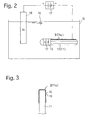
- the band-like handsaw substrate 11, of which the diamond abrasive is provisionally applied to the cutter blade forming portion 11a is thereafter dipped in an electrolytic deposition tank (plating tank) 15, as shown in Figure 2 .
- the electrolytic deposition tank 15 is filled with electrolytic solution (solution of nickel compound such as nickel sulfate) 16.
- electrolytic solution 16 solution of nickel compound such as nickel sulfate
- a cathode connected to an external DC power source 17 is connected to the band-like handsaw substrate 11 and an anode is connected to a nickel plate 18.
- oxidation and reduction occur at the cathode and anode, respectively. Consequently, nickel is electrolytically deposited (plated) on the cutter blade forming portion 11a connected to the cathode.
- a nickel deposition layer (metal deposition layer) 19 is formed.
- the formation of the nickel deposition layer 19 causes the diamond abrasive 14 to be firmly embedded in the nickel deposition layer 19.
- a blade portion 9 of hard abrasive is deposited in the form of generally u, onto the blade forming portion 11a of the band-like handsaw 11.
- the electrolytic deposition can be carried out at one time for a number of band-like handsaw substrates 11.
- a grip body 20 shown in Figure 4 is formed (or machined) independently of the electrolytic deposition of the band-like handsaw substrate 11.
- the grip body 20 is made of, for example, synthetic resin, and is constructed from two halves 21 and 22 which are split with respect to a center plane of the thickness of the handsaw substrate 11.
- the grip half 21 is provided with two securing projections 21a which are fitted in the two holes 12 of the handsaw substrate 11.
- the other grip half 22 is provided with two receptacles 22a corresponding to the securing projections 21a.
- the grip halves 21 and 22 are provided, on the peripheral edges thereof, with inter-engageable projections and recesses 21b and 22b, respectively.
- the blade portion 9 of hard abrasive is not provided on the portion of the handsaw substrate 11 that is covered by the grip body 20.
- the blade portion 9 of hard abrasive may be provided on both edges of the handsaw substrate 11 with respect to the width direction thereof.
- the end of the handsaw substrate 11, which has been subjected to the electrolytic deposition, adjacent to the holes 12 is covered by the grip halves 21 and 22 and the projections 21a are fitted in the holes 12. Thereafter, the grip halves 21 and 22 are connected through the inter-engageable projections and recesses 21b and 22b. As a result, a handsaw 100 capable of cutting a glass bottle, having the grip body 20 at one end can be obtained.
- Figure 5 shows a cutting operation of a bottom portion of a glass bottle 200 (wine bottle) using the handsaw 100 thus obtained.
- the glass bottle 200 whose bottom has been cut off can be turned upside-down and be reused, for example, as a flowerpot.
- Figure 7 shows an embodiment of a handsaw 300 having a body frame in the form of a hacksaw frame 30.
- the hacksaw frame 30 is generally in the form of a U-shape.
- the open end of the hacksaw frame is provided with a stationary pin 31 and a movable pin 32.
- the movable pin 32 is rotatably supported by the front end of a screw rod 33.
- the handsaw substrate 11' is provided, on its opposite ends in the length direction, with holes 15 in which the stationary pin 31 and the movable pin 32 are fitted.
- the handsaw substrate 11' is also provided, on one side thereof in the width direction, with a blade portion 9 of hard abrasive, which is formed by electrolytic deposition of diamond abrasive 14 as in the above-described embodiment.
- the blade portion 9 can be obtained in the same way as that shown in Figure 2.
- the stationary pin 31 and the movable pin 32 are fitted in the pin holes 15 of the handsaw substrate 11'. Thereafter, when the screw rod 33 is moved in the axial direction, the handsaw substrate 11' is secured to the hacksaw frame 30.
- the hacksaw can be used as a handsaw in the same way as the grip-type saw in order to cut, for example, a glass bottle.
- the metal to be electrolytically deposited on the band-like handsaw substrate 11 is nickel in the illustrated embodiments, it is possible to use other metals, such as copper.
- the electrolytic deposition can be replaced with electroless plating, etc.
- the diamond abrasive can be replaced with cubic boron nitride (CBN) abrasive, etc.
- the handsaw can also be used to cut other objects other than the glass bottle.
- a handsaw capable of cutting a glass bottle for domestic use can be obtained.
Landscapes
- Engineering & Computer Science (AREA)
- Mechanical Engineering (AREA)
- Mining & Mineral Resources (AREA)
- Polishing Bodies And Polishing Tools (AREA)
- Re-Forming, After-Treatment, Cutting And Transporting Of Glass Products (AREA)
- Knives (AREA)
- Sawing (AREA)
- Finish Polishing, Edge Sharpening, And Grinding By Specific Grinding Devices (AREA)
- Manufacture, Treatment Of Glass Fibers (AREA)
Applications Claiming Priority (2)
| Application Number | Priority Date | Filing Date | Title |
|---|---|---|---|
| JP2000308833 | 2000-10-10 | ||
| JP2000308833A JP2002113666A (ja) | 2000-10-10 | 2000-10-10 | ガラス瓶を切断可能な手鋸及びその製造方法 |
Publications (3)
| Publication Number | Publication Date |
|---|---|
| EP1197308A2 true EP1197308A2 (de) | 2002-04-17 |
| EP1197308A3 EP1197308A3 (de) | 2003-04-02 |
| EP1197308B1 EP1197308B1 (de) | 2008-05-14 |
Family
ID=18789086
Family Applications (1)
| Application Number | Title | Priority Date | Filing Date |
|---|---|---|---|
| EP01124124A Expired - Lifetime EP1197308B1 (de) | 2000-10-10 | 2001-10-10 | Handsäge geeignet zum Schneiden von Glasflaschen, Verfahren zu ihrer Herstellung, und Verfahren zur Wiederverwendung leerer Weinflaschen |
Country Status (5)
| Country | Link |
|---|---|
| US (2) | US6811477B2 (de) |
| EP (1) | EP1197308B1 (de) |
| JP (1) | JP2002113666A (de) |
| AT (1) | ATE395172T1 (de) |
| DE (1) | DE60133977D1 (de) |
Cited By (2)
| Publication number | Priority date | Publication date | Assignee | Title |
|---|---|---|---|---|
| EP1314504A3 (de) * | 2001-11-26 | 2003-09-10 | Kapman AB | Handsäge und Verfahren bezüglich der Herstellung einer Handsäge |
| US7222555B2 (en) * | 2000-10-10 | 2007-05-29 | Funasaw Co., Ltd. | Method of manufacturing a hacksaw |
Families Citing this family (7)
| Publication number | Priority date | Publication date | Assignee | Title |
|---|---|---|---|---|
| AT500151B1 (de) * | 2002-08-12 | 2007-09-15 | Boehler Uddeholm Prec Strip Gm | Vormaterial für sägeblätter oder sägebänder |
| US8372086B2 (en) * | 2004-08-09 | 2013-02-12 | Lesley Lind | Skin care file and method |
| US8091386B2 (en) * | 2007-11-29 | 2012-01-10 | Kathleen Marie Plate | Recycled glass items and method of making |
| US9809484B2 (en) | 2012-06-19 | 2017-11-07 | Patrick Lehoux | Bottle cutter |
| US9427882B1 (en) * | 2013-07-26 | 2016-08-30 | Ronald Wagoner | Pocket safety saw |
| EP3623092A1 (de) * | 2018-09-11 | 2020-03-18 | Voestalpine Precision Strip GmbH | Klinge für eine gattersäge |
| US11485672B2 (en) | 2021-07-08 | 2022-11-01 | Qi Zheng | Glass bottle cutter based on electric heating |
Family Cites Families (32)
| Publication number | Priority date | Publication date | Assignee | Title |
|---|---|---|---|---|
| US2924050A (en) * | 1960-02-09 | Diamond edged band saw | ||
| US2784536A (en) * | 1955-10-03 | 1957-03-12 | Lee H Barron | Diamond band saw |
| US3630699A (en) | 1969-09-02 | 1971-12-28 | Remington Arms Co Inc | Method for producing armored saber saws |
| BE759534A (fr) | 1969-11-28 | 1971-04-30 | Kayex Corp | Element de decoupe abrasif |
| US3785938A (en) * | 1970-11-05 | 1974-01-15 | A Sam | Method for making abrasive articles |
| US3874126A (en) | 1971-10-15 | 1975-04-01 | Remington Arms Co Inc | Flexible hand held abrading tool |
| US3956858A (en) | 1973-11-23 | 1976-05-18 | Remington Arms Company, Inc. | Flexible hand held abrading tool |
| DE2939306C2 (de) * | 1979-09-28 | 1984-02-23 | Fa. A. Raymond, 7850 Lörrach | Haltegriff aus plastischem Material für Halteblätter an Haushaltsgeräten |
| JPS578894A (en) | 1980-06-17 | 1982-01-18 | Toyo Kogyo Co | Acoustic device for vehicle |
| JPS57178669A (en) * | 1981-04-23 | 1982-11-02 | Daiyamondo Giken Kk | Cutting edge |
| FR2555930A1 (fr) | 1983-12-01 | 1985-06-07 | Degrenne Sa Guy | Instrument ou outil a main tel qu'un couvert, comportant un manche compose de deux moities enserrant la soie de l'outil |
| JPS628068U (de) * | 1985-06-28 | 1987-01-19 | ||
| EP0263618A3 (de) | 1986-10-02 | 1989-10-04 | Emhart Glass Machinery Investments Inc. | Untersuchungsgerät |
| JPS6360440U (de) * | 1986-10-07 | 1988-04-22 | ||
| JPS63115039U (de) * | 1987-01-14 | 1988-07-25 | ||
| JPH069764Y2 (ja) * | 1987-10-30 | 1994-03-16 | 弘道 田中 | 合成樹脂柄の鋸 |
| JPH0727123Y2 (ja) * | 1988-06-20 | 1995-06-21 | 株式会社ユーエム工業 | 手引き鋸 |
| JPH0716801B2 (ja) | 1988-06-29 | 1995-03-01 | 日立精機株式会社 | 複合加工用旋盤 |
| US5024680A (en) * | 1988-11-07 | 1991-06-18 | Norton Company | Multiple metal coated superabrasive grit and methods for their manufacture |
| JPH0360980A (ja) | 1989-07-27 | 1991-03-15 | Nachi Fujikoshi Corp | 切断加工工具 |
| JPH0360980U (de) * | 1989-10-17 | 1991-06-14 | ||
| GB9103883D0 (en) * | 1991-02-25 | 1991-04-10 | Black & Decker Inc | Saw blades and method of making same |
| JP3302054B2 (ja) * | 1992-10-01 | 2002-07-15 | 株式会社小松製作所 | 電着方法 |
| US5443417A (en) * | 1992-11-18 | 1995-08-22 | Sunnen Products Company | On edge honing devices |
| DE4322544C1 (de) * | 1993-07-07 | 1995-03-02 | Fein C & E | Verfahren zum Sägen von duktilen Eisenwerkstoffen |
| US5524350A (en) * | 1994-07-15 | 1996-06-11 | Glassmaster Company | Cutting line filled with inorganic grit material |
| JPH0985530A (ja) * | 1995-09-27 | 1997-03-31 | Noritake Dia Kk | 帯鋸切断刃 |
| US5975989A (en) * | 1997-12-31 | 1999-11-02 | Thiel; William C. | Detail tape |
| JP3992168B2 (ja) * | 1998-09-17 | 2007-10-17 | 株式会社ディスコ | 電着ブレードの製造方法 |
| JP3469516B2 (ja) * | 1999-12-09 | 2003-11-25 | 株式会社アルテクス | 超音波振動切断用ツール及びその製造方法 |
| JP2002113666A (ja) * | 2000-10-10 | 2002-04-16 | Funasoo Kk | ガラス瓶を切断可能な手鋸及びその製造方法 |
| JP2002326166A (ja) * | 2001-04-26 | 2002-11-12 | Tsune Seiki Co Ltd | 電着薄刃砥石とその製造方法 |
-
2000
- 2000-10-10 JP JP2000308833A patent/JP2002113666A/ja active Pending
-
2001
- 2001-10-09 US US09/972,239 patent/US6811477B2/en not_active Expired - Fee Related
- 2001-10-10 EP EP01124124A patent/EP1197308B1/de not_active Expired - Lifetime
- 2001-10-10 DE DE60133977T patent/DE60133977D1/de not_active Expired - Lifetime
- 2001-10-10 AT AT01124124T patent/ATE395172T1/de not_active IP Right Cessation
-
2004
- 2004-11-02 US US10/978,356 patent/US7222555B2/en not_active Expired - Fee Related
Cited By (2)
| Publication number | Priority date | Publication date | Assignee | Title |
|---|---|---|---|---|
| US7222555B2 (en) * | 2000-10-10 | 2007-05-29 | Funasaw Co., Ltd. | Method of manufacturing a hacksaw |
| EP1314504A3 (de) * | 2001-11-26 | 2003-09-10 | Kapman AB | Handsäge und Verfahren bezüglich der Herstellung einer Handsäge |
Also Published As
| Publication number | Publication date |
|---|---|
| ATE395172T1 (de) | 2008-05-15 |
| EP1197308B1 (de) | 2008-05-14 |
| US6811477B2 (en) | 2004-11-02 |
| US20050092134A1 (en) | 2005-05-05 |
| EP1197308A3 (de) | 2003-04-02 |
| US7222555B2 (en) | 2007-05-29 |
| DE60133977D1 (de) | 2008-06-26 |
| US20020040626A1 (en) | 2002-04-11 |
| JP2002113666A (ja) | 2002-04-16 |
Similar Documents
| Publication | Publication Date | Title |
|---|---|---|
| US6811477B2 (en) | Handsaw capable of cutting glass bottle, method for manufacturing the same, and method for re-using empty wine bottle | |
| CN102481647B (zh) | 包括粘结到长形本体上的磨料颗粒的磨料物品 | |
| MY136961A (en) | Superabrasive wire saw and method for making the saw. | |
| TW370572B (en) | Razor blades and shaving units improved by hard-carbon coating with amorphous diamond and process for preparing them | |
| JP2006181698A (ja) | 電着ワイヤ工具 | |
| CN102036790A (zh) | 刀具 | |
| CN102574275A (zh) | 固定磨粒线及其制造方法以及用于该固定磨粒线的磨粒 | |
| SE9701900D0 (sv) | Hållare för svarvoperationer | |
| US20060010696A1 (en) | Hand tool with cutting blade having cutting surfaces with wear-enhancing coating thereon | |
| AU1553999A (en) | Cutting tool and method for coating cutting tools | |
| EP0720887B1 (de) | Schneidwerkzeug | |
| JP4397193B2 (ja) | 電着バンドソー | |
| CN204431412U (zh) | 一种硬质合金锯片刀头 | |
| ES2190332A1 (es) | Procedimiento para la diseccion milimetrica de marmol, piedras o materiales similares. | |
| CA3141625A1 (en) | Band-shaped machining tool having buffer particles | |
| EP0247217A1 (de) | Selbstschärfendes Schneidegerät und Verfahren zu dessen Herstellung | |
| Schroeder et al. | Diamond tools in the machining of glass fiber-reinforced plastics | |
| KR100512266B1 (ko) | 칼갈이 봉 | |
| RU2001103054A (ru) | Способ изготовления режущей пластинки для обработки металлических инструментов резанием | |
| DE59303432D1 (de) | Schneidleiste hoher Abnutzungsfestigkeit und Verfahren zu ihrer Herstellung | |
| MX9605052A (es) | Recubrimiento de diamante amorfo de hojas de afeitar. | |
| EP1036623A3 (de) | Gehrungssäge | |
| TH98721A (th) | ผิวเคลือบเพชรอสัณฐานของใบมีด | |
| JPH0529671U (ja) | 切断用工具 | |
| RO121477B1 (ro) | Procedeu de placare cu oţel rapid, prin depunerecu laser |
Legal Events
| Date | Code | Title | Description |
|---|---|---|---|
| PUAI | Public reference made under article 153(3) epc to a published international application that has entered the european phase |
Free format text: ORIGINAL CODE: 0009012 |
|
| AK | Designated contracting states |
Kind code of ref document: A2 Designated state(s): AT BE CH CY DE DK ES FI FR GB GR IE IT LI LU MC NL PT SE TR |
|
| AX | Request for extension of the european patent |
Free format text: AL;LT;LV;MK;RO;SI |
|
| PUAL | Search report despatched |
Free format text: ORIGINAL CODE: 0009013 |
|
| AK | Designated contracting states |
Kind code of ref document: A3 Designated state(s): AT BE CH CY DE DK ES FI FR GB GR IE IT LI LU MC NL PT SE TR |
|
| AX | Request for extension of the european patent |
Extension state: AL LT LV MK RO SI |
|
| 17P | Request for examination filed |
Effective date: 20030905 |
|
| AKX | Designation fees paid |
Designated state(s): AT BE CH CY DE DK ES FI FR GB GR IE IT LI LU MC NL PT SE TR |
|
| GRAP | Despatch of communication of intention to grant a patent |
Free format text: ORIGINAL CODE: EPIDOSNIGR1 |
|
| RIN1 | Information on inventor provided before grant (corrected) |
Inventor name: FUNAKUBO, MASAYOSHI,C/O FUNASAW CO., LTD. |
|
| GRAS | Grant fee paid |
Free format text: ORIGINAL CODE: EPIDOSNIGR3 |
|
| GRAA | (expected) grant |
Free format text: ORIGINAL CODE: 0009210 |
|
| AK | Designated contracting states |
Kind code of ref document: B1 Designated state(s): AT BE CH CY DE DK ES FI FR GB GR IE IT LI LU MC NL PT SE TR |
|
| REG | Reference to a national code |
Ref country code: GB Ref legal event code: FG4D |
|
| REG | Reference to a national code |
Ref country code: CH Ref legal event code: EP |
|
| REG | Reference to a national code |
Ref country code: IE Ref legal event code: FG4D Free format text: LANGUAGE OF EP DOCUMENT: FRENCH |
|
| REF | Corresponds to: |
Ref document number: 60133977 Country of ref document: DE Date of ref document: 20080626 Kind code of ref document: P |
|
| PG25 | Lapsed in a contracting state [announced via postgrant information from national office to epo] |
Ref country code: ES Free format text: LAPSE BECAUSE OF FAILURE TO SUBMIT A TRANSLATION OF THE DESCRIPTION OR TO PAY THE FEE WITHIN THE PRESCRIBED TIME-LIMIT Effective date: 20080825 Ref country code: FI Free format text: LAPSE BECAUSE OF FAILURE TO SUBMIT A TRANSLATION OF THE DESCRIPTION OR TO PAY THE FEE WITHIN THE PRESCRIBED TIME-LIMIT Effective date: 20080514 |
|
| NLV1 | Nl: lapsed or annulled due to failure to fulfill the requirements of art. 29p and 29m of the patents act | ||
| PG25 | Lapsed in a contracting state [announced via postgrant information from national office to epo] |
Ref country code: AT Free format text: LAPSE BECAUSE OF FAILURE TO SUBMIT A TRANSLATION OF THE DESCRIPTION OR TO PAY THE FEE WITHIN THE PRESCRIBED TIME-LIMIT Effective date: 20080514 Ref country code: NL Free format text: LAPSE BECAUSE OF FAILURE TO SUBMIT A TRANSLATION OF THE DESCRIPTION OR TO PAY THE FEE WITHIN THE PRESCRIBED TIME-LIMIT Effective date: 20080514 |
|
| PG25 | Lapsed in a contracting state [announced via postgrant information from national office to epo] |
Ref country code: SE Free format text: LAPSE BECAUSE OF FAILURE TO SUBMIT A TRANSLATION OF THE DESCRIPTION OR TO PAY THE FEE WITHIN THE PRESCRIBED TIME-LIMIT Effective date: 20080814 Ref country code: DK Free format text: LAPSE BECAUSE OF FAILURE TO SUBMIT A TRANSLATION OF THE DESCRIPTION OR TO PAY THE FEE WITHIN THE PRESCRIBED TIME-LIMIT Effective date: 20080514 Ref country code: PT Free format text: LAPSE BECAUSE OF FAILURE TO SUBMIT A TRANSLATION OF THE DESCRIPTION OR TO PAY THE FEE WITHIN THE PRESCRIBED TIME-LIMIT Effective date: 20081014 |
|
| PG25 | Lapsed in a contracting state [announced via postgrant information from national office to epo] |
Ref country code: BE Free format text: LAPSE BECAUSE OF FAILURE TO SUBMIT A TRANSLATION OF THE DESCRIPTION OR TO PAY THE FEE WITHIN THE PRESCRIBED TIME-LIMIT Effective date: 20080514 |
|
| PLBE | No opposition filed within time limit |
Free format text: ORIGINAL CODE: 0009261 |
|
| STAA | Information on the status of an ep patent application or granted ep patent |
Free format text: STATUS: NO OPPOSITION FILED WITHIN TIME LIMIT |
|
| 26N | No opposition filed |
Effective date: 20090217 |
|
| PG25 | Lapsed in a contracting state [announced via postgrant information from national office to epo] |
Ref country code: MC Free format text: LAPSE BECAUSE OF NON-PAYMENT OF DUE FEES Effective date: 20081031 |
|
| REG | Reference to a national code |
Ref country code: CH Ref legal event code: PL |
|
| REG | Reference to a national code |
Ref country code: IE Ref legal event code: MM4A |
|
| PG25 | Lapsed in a contracting state [announced via postgrant information from national office to epo] |
Ref country code: IE Free format text: LAPSE BECAUSE OF NON-PAYMENT OF DUE FEES Effective date: 20081010 Ref country code: CH Free format text: LAPSE BECAUSE OF NON-PAYMENT OF DUE FEES Effective date: 20081031 Ref country code: LI Free format text: LAPSE BECAUSE OF NON-PAYMENT OF DUE FEES Effective date: 20081031 |
|
| PG25 | Lapsed in a contracting state [announced via postgrant information from national office to epo] |
Ref country code: LU Free format text: LAPSE BECAUSE OF NON-PAYMENT OF DUE FEES Effective date: 20081010 Ref country code: CY Free format text: LAPSE BECAUSE OF FAILURE TO SUBMIT A TRANSLATION OF THE DESCRIPTION OR TO PAY THE FEE WITHIN THE PRESCRIBED TIME-LIMIT Effective date: 20080514 |
|
| PG25 | Lapsed in a contracting state [announced via postgrant information from national office to epo] |
Ref country code: TR Free format text: LAPSE BECAUSE OF FAILURE TO SUBMIT A TRANSLATION OF THE DESCRIPTION OR TO PAY THE FEE WITHIN THE PRESCRIBED TIME-LIMIT Effective date: 20080514 |
|
| PG25 | Lapsed in a contracting state [announced via postgrant information from national office to epo] |
Ref country code: GR Free format text: LAPSE BECAUSE OF FAILURE TO SUBMIT A TRANSLATION OF THE DESCRIPTION OR TO PAY THE FEE WITHIN THE PRESCRIBED TIME-LIMIT Effective date: 20080815 |
|
| PGFP | Annual fee paid to national office [announced via postgrant information from national office to epo] |
Ref country code: DE Payment date: 20141125 Year of fee payment: 14 Ref country code: FR Payment date: 20141021 Year of fee payment: 14 Ref country code: GB Payment date: 20141024 Year of fee payment: 14 |
|
| PGFP | Annual fee paid to national office [announced via postgrant information from national office to epo] |
Ref country code: IT Payment date: 20141027 Year of fee payment: 14 |
|
| REG | Reference to a national code |
Ref country code: DE Ref legal event code: R082 Ref document number: 60133977 Country of ref document: DE Representative=s name: SCHAUMBURG & PARTNER PATENTANWAELTE GBR, DE Ref country code: DE Ref legal event code: R082 Ref document number: 60133977 Country of ref document: DE Representative=s name: SCHAUMBURG & PARTNER PATENTANWAELTE MBB, DE Ref country code: DE Ref legal event code: R082 Ref document number: 60133977 Country of ref document: DE Representative=s name: SCHAUMBURG UND PARTNER PATENTANWAELTE MBB, DE |
|
| REG | Reference to a national code |
Ref country code: DE Ref legal event code: R119 Ref document number: 60133977 Country of ref document: DE |
|
| GBPC | Gb: european patent ceased through non-payment of renewal fee |
Effective date: 20151010 |
|
| PG25 | Lapsed in a contracting state [announced via postgrant information from national office to epo] |
Ref country code: IT Free format text: LAPSE BECAUSE OF NON-PAYMENT OF DUE FEES Effective date: 20151010 Ref country code: DE Free format text: LAPSE BECAUSE OF NON-PAYMENT OF DUE FEES Effective date: 20160503 Ref country code: GB Free format text: LAPSE BECAUSE OF NON-PAYMENT OF DUE FEES Effective date: 20151010 |
|
| REG | Reference to a national code |
Ref country code: FR Ref legal event code: ST Effective date: 20160630 |
|
| PG25 | Lapsed in a contracting state [announced via postgrant information from national office to epo] |
Ref country code: FR Free format text: LAPSE BECAUSE OF NON-PAYMENT OF DUE FEES Effective date: 20151102 |