EP1195508B1 - Verfahren zum Betrieb einer Abgasreinigungsanlage einer Brennkraftmaschine eines Kraftfahrzeugs - Google Patents
Verfahren zum Betrieb einer Abgasreinigungsanlage einer Brennkraftmaschine eines Kraftfahrzeugs Download PDFInfo
- Publication number
- EP1195508B1 EP1195508B1 EP01123985A EP01123985A EP1195508B1 EP 1195508 B1 EP1195508 B1 EP 1195508B1 EP 01123985 A EP01123985 A EP 01123985A EP 01123985 A EP01123985 A EP 01123985A EP 1195508 B1 EP1195508 B1 EP 1195508B1
- Authority
- EP
- European Patent Office
- Prior art keywords
- operating
- regeneration
- exhaust gas
- profile
- gas purification
- Prior art date
- Legal status (The legal status is an assumption and is not a legal conclusion. Google has not performed a legal analysis and makes no representation as to the accuracy of the status listed.)
- Expired - Lifetime
Links
Images


Classifications
-
- F—MECHANICAL ENGINEERING; LIGHTING; HEATING; WEAPONS; BLASTING
- F01—MACHINES OR ENGINES IN GENERAL; ENGINE PLANTS IN GENERAL; STEAM ENGINES
- F01N—GAS-FLOW SILENCERS OR EXHAUST APPARATUS FOR MACHINES OR ENGINES IN GENERAL; GAS-FLOW SILENCERS OR EXHAUST APPARATUS FOR INTERNAL-COMBUSTION ENGINES
- F01N9/00—Electrical control of exhaust gas treating apparatus
-
- F—MECHANICAL ENGINEERING; LIGHTING; HEATING; WEAPONS; BLASTING
- F01—MACHINES OR ENGINES IN GENERAL; ENGINE PLANTS IN GENERAL; STEAM ENGINES
- F01N—GAS-FLOW SILENCERS OR EXHAUST APPARATUS FOR MACHINES OR ENGINES IN GENERAL; GAS-FLOW SILENCERS OR EXHAUST APPARATUS FOR INTERNAL-COMBUSTION ENGINES
- F01N3/00—Exhaust or silencing apparatus having means for purifying, rendering innocuous, or otherwise treating exhaust
- F01N3/02—Exhaust or silencing apparatus having means for purifying, rendering innocuous, or otherwise treating exhaust for cooling, or for removing solid constituents of, exhaust
- F01N3/021—Exhaust or silencing apparatus having means for purifying, rendering innocuous, or otherwise treating exhaust for cooling, or for removing solid constituents of, exhaust by means of filters
- F01N3/023—Exhaust or silencing apparatus having means for purifying, rendering innocuous, or otherwise treating exhaust for cooling, or for removing solid constituents of, exhaust by means of filters using means for regenerating the filters, e.g. by burning trapped particles
-
- F—MECHANICAL ENGINEERING; LIGHTING; HEATING; WEAPONS; BLASTING
- F01—MACHINES OR ENGINES IN GENERAL; ENGINE PLANTS IN GENERAL; STEAM ENGINES
- F01N—GAS-FLOW SILENCERS OR EXHAUST APPARATUS FOR MACHINES OR ENGINES IN GENERAL; GAS-FLOW SILENCERS OR EXHAUST APPARATUS FOR INTERNAL-COMBUSTION ENGINES
- F01N3/00—Exhaust or silencing apparatus having means for purifying, rendering innocuous, or otherwise treating exhaust
- F01N3/08—Exhaust or silencing apparatus having means for purifying, rendering innocuous, or otherwise treating exhaust for rendering innocuous
- F01N3/0807—Exhaust or silencing apparatus having means for purifying, rendering innocuous, or otherwise treating exhaust for rendering innocuous by using absorbents or adsorbents
- F01N3/0871—Exhaust or silencing apparatus having means for purifying, rendering innocuous, or otherwise treating exhaust for rendering innocuous by using absorbents or adsorbents using means for controlling, e.g. purging, the absorbents or adsorbents
-
- F—MECHANICAL ENGINEERING; LIGHTING; HEATING; WEAPONS; BLASTING
- F02—COMBUSTION ENGINES; HOT-GAS OR COMBUSTION-PRODUCT ENGINE PLANTS
- F02D—CONTROLLING COMBUSTION ENGINES
- F02D41/00—Electrical control of supply of combustible mixture or its constituents
- F02D41/02—Circuit arrangements for generating control signals
- F02D41/021—Introducing corrections for particular conditions exterior to the engine
-
- F—MECHANICAL ENGINEERING; LIGHTING; HEATING; WEAPONS; BLASTING
- F02—COMBUSTION ENGINES; HOT-GAS OR COMBUSTION-PRODUCT ENGINE PLANTS
- F02D—CONTROLLING COMBUSTION ENGINES
- F02D41/00—Electrical control of supply of combustible mixture or its constituents
- F02D41/02—Circuit arrangements for generating control signals
- F02D41/021—Introducing corrections for particular conditions exterior to the engine
- F02D41/0235—Introducing corrections for particular conditions exterior to the engine in relation with the state of the exhaust gas treating apparatus
- F02D41/027—Introducing corrections for particular conditions exterior to the engine in relation with the state of the exhaust gas treating apparatus to purge or regenerate the exhaust gas treating apparatus
-
- F—MECHANICAL ENGINEERING; LIGHTING; HEATING; WEAPONS; BLASTING
- F02—COMBUSTION ENGINES; HOT-GAS OR COMBUSTION-PRODUCT ENGINE PLANTS
- F02D—CONTROLLING COMBUSTION ENGINES
- F02D2200/00—Input parameters for engine control
- F02D2200/50—Input parameters for engine control said parameters being related to the vehicle or its components
- F02D2200/501—Vehicle speed
-
- F—MECHANICAL ENGINEERING; LIGHTING; HEATING; WEAPONS; BLASTING
- F02—COMBUSTION ENGINES; HOT-GAS OR COMBUSTION-PRODUCT ENGINE PLANTS
- F02D—CONTROLLING COMBUSTION ENGINES
- F02D2200/00—Input parameters for engine control
- F02D2200/70—Input parameters for engine control said parameters being related to the vehicle exterior
- F02D2200/701—Information about vehicle position, e.g. from navigation system or GPS signal
-
- F—MECHANICAL ENGINEERING; LIGHTING; HEATING; WEAPONS; BLASTING
- F02—COMBUSTION ENGINES; HOT-GAS OR COMBUSTION-PRODUCT ENGINE PLANTS
- F02D—CONTROLLING COMBUSTION ENGINES
- F02D41/00—Electrical control of supply of combustible mixture or its constituents
- F02D41/02—Circuit arrangements for generating control signals
- F02D41/021—Introducing corrections for particular conditions exterior to the engine
- F02D41/0235—Introducing corrections for particular conditions exterior to the engine in relation with the state of the exhaust gas treating apparatus
- F02D41/027—Introducing corrections for particular conditions exterior to the engine in relation with the state of the exhaust gas treating apparatus to purge or regenerate the exhaust gas treating apparatus
- F02D41/0275—Introducing corrections for particular conditions exterior to the engine in relation with the state of the exhaust gas treating apparatus to purge or regenerate the exhaust gas treating apparatus the exhaust gas treating apparatus being a NOx trap or adsorbent
-
- F—MECHANICAL ENGINEERING; LIGHTING; HEATING; WEAPONS; BLASTING
- F02—COMBUSTION ENGINES; HOT-GAS OR COMBUSTION-PRODUCT ENGINE PLANTS
- F02D—CONTROLLING COMBUSTION ENGINES
- F02D41/00—Electrical control of supply of combustible mixture or its constituents
- F02D41/02—Circuit arrangements for generating control signals
- F02D41/021—Introducing corrections for particular conditions exterior to the engine
- F02D41/0235—Introducing corrections for particular conditions exterior to the engine in relation with the state of the exhaust gas treating apparatus
- F02D41/027—Introducing corrections for particular conditions exterior to the engine in relation with the state of the exhaust gas treating apparatus to purge or regenerate the exhaust gas treating apparatus
- F02D41/029—Introducing corrections for particular conditions exterior to the engine in relation with the state of the exhaust gas treating apparatus to purge or regenerate the exhaust gas treating apparatus the exhaust gas treating apparatus being a particulate filter
-
- F—MECHANICAL ENGINEERING; LIGHTING; HEATING; WEAPONS; BLASTING
- F02—COMBUSTION ENGINES; HOT-GAS OR COMBUSTION-PRODUCT ENGINE PLANTS
- F02D—CONTROLLING COMBUSTION ENGINES
- F02D41/00—Electrical control of supply of combustible mixture or its constituents
- F02D41/02—Circuit arrangements for generating control signals
- F02D41/14—Introducing closed-loop corrections
- F02D41/1438—Introducing closed-loop corrections using means for determining characteristics of the combustion gases; Sensors therefor
- F02D41/1444—Introducing closed-loop corrections using means for determining characteristics of the combustion gases; Sensors therefor characterised by the characteristics of the combustion gases
- F02D41/1446—Introducing closed-loop corrections using means for determining characteristics of the combustion gases; Sensors therefor characterised by the characteristics of the combustion gases the characteristics being exhaust temperatures
-
- Y—GENERAL TAGGING OF NEW TECHNOLOGICAL DEVELOPMENTS; GENERAL TAGGING OF CROSS-SECTIONAL TECHNOLOGIES SPANNING OVER SEVERAL SECTIONS OF THE IPC; TECHNICAL SUBJECTS COVERED BY FORMER USPC CROSS-REFERENCE ART COLLECTIONS [XRACs] AND DIGESTS
- Y02—TECHNOLOGIES OR APPLICATIONS FOR MITIGATION OR ADAPTATION AGAINST CLIMATE CHANGE
- Y02T—CLIMATE CHANGE MITIGATION TECHNOLOGIES RELATED TO TRANSPORTATION
- Y02T10/00—Road transport of goods or passengers
- Y02T10/10—Internal combustion engine [ICE] based vehicles
- Y02T10/40—Engine management systems
Definitions
- the invention relates to a method for operating an emission control system an internal combustion engine of a motor vehicle according to the preamble of claim 1.
- At least one emission control operating parameter supervised. If given Regeneration start conditions are present, a regeneration operating state for at least partial regeneration of Emission control system activated. It belongs to the regeneration start conditions, that the at least one emission control operating parameter a predefinable target operating range has left.
- particle filters or NOx storage catalysts require regeneration of the exhaust aftertreatment device from time to time.
- particle filters it is necessary, for example, to burn off the deposited particles, so that the filter is able to continue to carry out its filter function.
- NOx storage catalytic converters regeneration is required at the latest when the storage capacity of the storage catalytic converter is exhausted. There must then be a desorption to the reaction of the stored NOx compounds, with a simultaneous reduction of NO x compounds should take place.
- Such regeneration mechanisms are well known.
- the regeneration of exhaust aftertreatment devices of Exhaust gas purification system often requires that the Exhaust gas aftertreatment device to high temperatures, in particular to temperatures in the temperature range above 450 ° C to 650 ° C is heated.
- the object of the invention is to activate the regeneration operating state perform so that at least one Partial regeneration of the emission control system if possible low additional energy consumption in customer operation reliable is feasible.
- the object of the invention is in Switzerlanddorfdorfer the generic Method according to the invention by a method with the characterizing features of claim 1 solved.
- an internal combustion engine of a motor vehicle is monitors at least one emission control operating parameter.
- One Regeneration mode for at least partial regeneration the emission control system is always activated, if predetermined regeneration start conditions exist. To heard this regeneration start conditions that the at least an emission control operating parameters a predetermined Has left the target operating range. It will be during the Operation of the combustion device a specific Operating profile determined the same. The nominal operating range of the at least one emission control operating parameter is thereby depending on the determined operating profile variable specified.
- the desired operating range for the at least one Emission control operating parameters to that in this vehicle adjusted operating profile adapted.
- the regeneration operating state is activated as possible when the Conditions for carrying out at least partial Regeneration of the emission control system are favorable. To this Way will be for the regeneration of the emission control system required additional energy consumption (additional fuel consumption) kept as low as possible.
- this is the Operating profile depending on different detected Size determined, these are preferably sizes that in the Vehicle can be detected or measured anyway.
- these Sizes may be, in particular, the current operating point the combustion device, for example, depending on the Speed and / or the injection quantity of fuel, the load state of the internal combustion engine, as he, for example from the mean injection quantity or the middle one Combustion chamber pressure results, the exhaust gas temperature and / or the vehicle speed act. It can be used to determine this Operating parameters not only the current value used but it can also over time the Frequency distribution of the operating parameters are determined and then used to determine the operating parameter become.
- the driving state a division into different, the driving condition characterizing classes that govern the operation of the Represent vehicle. Desired class divisions can thereby on the basis of logical connections, experience-based Associations or neural networks performed become.
- a possible division into classes for example the classes low load (idle mode / congestion), partial load (City traffic), upper part load (highway / out of town) and High load / full load (highway operation) include.
- To the division Driving conditions in different classes can be information used in engine management detected quantities are derived, such as the engine speed and the ignition timing.
- gear management recorded variables such as current transmission ratio and switching thresholds for the times of switching between the individual gear positions are used for it.
- a navigation system Information such as the determined route to Destination, to be used.
- This can also be done the time profile of the operating profile is recorded and from the comparison of the operating profile with others, earlier determined operating profiles to the expected future Operating profile to be closed.
- the current Operating profile and its timing with the earlier Company profiles and their timing and due to a similarity in the course of the operating profile then be concluded on the expected operating profile.
- the statistical frequency of the individual operating states, as they occur over time it allows to conclude how often favorable regeneration conditions available. If these are rare, they will, as soon as they are available, early regeneration. on the other hand you will have a regeneration in bad conditions and great likelihood of favorable conditions if possible pull out until good regeneration conditions are present.
- the more than one (exhaust) after-treatment device in each case, if more specific Regeneration start conditions to carry out an at least partial regeneration of the corresponding aftertreatment device takes place, the generation of regeneration operating conditions the aftertreatment devices matched.
- tuning the regeneration processes one thing to remember is that regeneration often takes place a second aftertreatment device without large further effort, especially without much additional Energy expenditure can be carried out after the regeneration the first exhaust aftertreatment device took place.
- the activation of a regeneration operating state is depending on the current operating status and the influenced to expected operating condition.
- the Regeneration be carried out so that, depending on the load value defines an optional limit and a mandatory limit of regeneration becomes.
- the limits can be determined by the determined driving profile still adapt to the operation of the vehicle, as stated above already explained. It is possible that before, while or after the regeneration of a first exhaust aftertreatment device a second exhaust aftertreatment device with moderately increased energy expenditure is regenerated, although the Loading this second exhaust aftertreatment device alone had not yet triggered a regeneration request.
- the Can limit for the regeneration start condition of an exhaust aftertreatment device must be exceeded before the Regeneration of an exhaust aftertreatment device performed becomes. After exceeding the mandatory limit by the regeneration start condition In any case, a regeneration takes place an exhaust aftertreatment device.
- Fig. 1 shows the time course of a regeneration process the regeneration of an emission control system or a Exhaust after-treatment device such.
- the regeneration process begins by fulfilling the regeneration start conditions.
- phase 1 and phase 2 the actual regeneration of the emission control system.
- the regeneration process While the regeneration process are in the exhaust aftertreatment device accumulated pollutants desorbed and thereby rendered harmless.
- the temperature becomes at the required elevated level, for example between 500 ° C and 600 ° C, held.
- With the end of Regeneration process is the regeneration of the emission control system completed. The temperature then lowers progressively back to the operating condition of the vehicle corresponding exhaust gas temperature.
- Fig. 2 shows a schematic representation of an example for how an operating profile based on operating points is determinable.
- the individual operating points over a corresponding map in example four areas or driving states split.
- Low engine speed and lower Brennraumdruck let it to the idle state or to close a low load state of the vehicle.
- With rising Speed and / or increasing average combustion chamber pressure is then to one area, the so-called lower part load range, as it occurs in city traffic, closed.
- With further increase in the speed and especially the middle Combustion chamber pressure is then limited to an upper part-load range, as it occurs during the overland journey, ie out of town, closed.
- the full load range which in the essentially the range of greatest mean combustion chamber pressures includes and is also in the upper speed range.
- Fig. 3 is shown in a schematic representation how due to the occurring exhaust gas temperature and the driving speed a classification of the current driving condition into different operating profiles, namely congestion, city traffic, Highway and highway can be made.
- Driving speeds below 30 km / h and at exhaust gas temperatures below 180 ° C becomes stuck or idle closed.
- At driving speeds in the range of 30 km / h up to 70 km / h and at exhaust gas temperatures between 180 ° C and 300 ° C is closed to operation in city traffic.
- On an upper part load range or a cross-country traffic is at exhaust gas temperatures between 300 ° C and 400 ° C and at driving speeds between 70 km / h and 120km / h closed.
- the overlying temperature range and the overlying speed range leaves on highway driving shut down.
- This classification can be the one according to Fig. 2 replace or supplement.
- An operating profile of a vehicle now includes the determination, which temporal part of the individual driving conditions with respect to is given on the total operating time.
- Fig. 4 shows the adaptation of the predetermined regeneration conditions to the determined Company profile. This is stated for five cases.
- the Operating profile case 1 (traffic jam)
- the driving state is "traffic jam” too given a time share of 100%.
- the Regeneration start conditions for the map area "traffic jam” kept constant while for the operating areas “Start, "Overland” and highway “the loading limit, so the loading from which the regeneration start conditions are met, lowered becomes.
- the further regeneration start condition “minimum Exhaust temperature” is kept constant, which causes then, when the operation area "congestion” is left, the regeneration start condition Loading limit is met very quickly and therefore triggered a regeneration operating state very early is, during which a regeneration of Emission control system is performed.
- Fig. 5 shows how the regeneration start conditions be customized to a different current Operating condition. While the corresponding Limit or threshold values which characterize the desired operating range, for example, as values for the idle state are set, the target operating range loading threshold the emission control system with increasing load profile and therefore lowered increased load of the vehicle. It will So a regeneration at an earlier date performed when the load conditions are high, such as this given on the highway ride. At the same time changes the temperature threshold of the exhaust gas temperature, from which the Performing a regeneration is allowed. This shifts up with increasing load of the vehicle.
- the comparison of operating profiles determined for the current journey determine with stored operating profiles whether one for the regeneration of the emission control system cheaper Driving condition is expected. If so, you can the regeneration starting conditions are adjusted so that at poor starting conditions, ie low state of the Motors, regeneration at a later date is performed to allow the beginning of regeneration as possible in to postpone a time of better regeneration conditions.
- the information of a Navigation system used for example can be derived, in what time and after which Driving distance in pursuit of the driver's planned route will leave the city traffic and for example the overland journey or the highway will start during the favorable regeneration conditions are to be expected.
- Fig. 6 shows how the control of regeneration can be performed when the emission control system several Aftertreatment devices comprises. This is shown in Fig. 6 for the case of two exhaust aftertreatment devices set forth. For each of the two exhaust gas aftertreatment is an optional regeneration start condition and a must regeneration start condition specified. Each of these regeneration start conditions can also according to the previously stated the operating profile can be adjusted. The initial values of Kann and the Muss jury are in each case by a Line shown while a blackened area around this Lines around represents the adaptation to the operating profile.
- FIG. 6 shows on the abscissa the regeneration condition for the exhaust aftertreatment device 1 shown. In one first, to the left of the can regeneration start condition Area becomes a regeneration of the exhaust aftertreatment device 1 not performed.
- a regeneration of the exhaust aftertreatment device 1 In a second area between the can regeneration start condition and the must regeneration start condition may be a regeneration of the exhaust aftertreatment device 1 done. It will, however, without that Existence of further circumstances not carried out. Right of the Line representing the must regeneration start condition the regeneration of the exhaust aftertreatment device 1 respectively. Accordingly, these areas are on the ordinate axis for the exhaust aftertreatment device 2 shown. It Thus, a subdivision of the possible states of Exhaust after-treatment equipment in nine fields. As long as one the two exhaust aftertreatment devices in one area is, in which the Kann-threshold has not been exceeded, becomes a regeneration of this one exhaust aftertreatment device regardless of whether the other exhaust aftertreatment device regenerated or not, not performed.
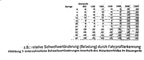
- Fig. 7 shows how the regeneration start conditions to the dependence on the current operating state can be specified.
- Fig. 7 shows a map in which depending the engine speed and the fuel injection quantity the percentage adjustment of the threshold for the maximum Loading the emission control system or an exhaust aftertreatment device this emission control system is shown. In cases of low injection quantity and low speed There is a small increase, for example, by 10%, the maximum Loading. With increasing speed or with increasing Injection amount, the threshold is initially set to a predetermined Leave the basic value. With further increasing speed or further increasing fuel injection quantity becomes the loading threshold value lowered by 20% or even by 40%, so that the regeneration due to the present more favorable conditions earlier performed at lower load values becomes. This value thus determined can then, as in relation on the Fig. 4 and 5 described, still on the driving profile or operating profile of the vehicle to be adjusted.
Landscapes
- Engineering & Computer Science (AREA)
- Chemical & Material Sciences (AREA)
- Combustion & Propulsion (AREA)
- Mechanical Engineering (AREA)
- General Engineering & Computer Science (AREA)
- Processes For Solid Components From Exhaust (AREA)
- Exhaust Gas After Treatment (AREA)
Description
- Abb. 1
- den schematischen Temperaturverlauf bei einer Regeneration einer Abgasnachbehandlungseinrichtung;
- Abb. 2
- eine schematische Kennfeldaufteilung für eine Fahrprofil-Ermittlung;
- Abb. 3
- eine Darstellung weiterer möglicher Beurteilungsgrößen für eine Fahrprofilerkennung;
- Abb. 4
- ein Beispiel für die Erkennung und Bewertung verschiedener Fahrprofile;
- Abb. 5
- ein Beispiel für eine dynamische Schwellwertanpassung in Abhängigkeit des Betriebprofils;
- Abb. 6
- ein Beispiel für die Anpassung der gekoppelten Durchführung von Regenerationsvorgängen bei zwei Abgasnachbehandlungseinrichtungen; und
- Abb. 7
- ein Beispiel für die relative Anpassung der Regenerationsstartbedingungen in Abhängigkeit des Betriebsprofils.
Claims (10)
- Verfahren zum Betrieb einer Abgasreinigungsanlage einer Brennkraftmaschine eines Kraftfahrzeugs, bei demdadurch gekennzeichnet, dasswenigstens ein Abgasreinigungs-Betriebsparameter überwacht und immer dann ein Regenerations-Betriebszustand zur wenigstens teilweisen Regeneration der Abgasreinigungsanlage aktiviert wird, wenn vorgegebene Regenerationsstartbedingungen vorliegen, zu denen gehört, dass der wenigstens eine Abgasreinigungs-Betriebsparameter einen vorgebbaren Sollbetriebsbereich verlassen hat, undein spezifisches Betriebsprofil der Brennkraftmaschine während ihres Betriebes ermittelt wird,der Sollbetriebsbereich einer Abgastemperatur als dem oder einem der Abgasreinigungs-Betriebsparameter in Abhängigkeit von dem ermittelten Betriebsprofil variabel vorgegeben wird und/oderdas spezifische Betriebsprofil den zeitlichen Anteil jedes von mehreren vorgebbaren Fahrzuständen des Kraftfahrzeuges in Bezug auf eine Gesamtbetriebszeit angibt und der Sollbetriebsbereich des wenigstens einen Abgasreinigungs-Betriebsparameters in Abhängigkeit von einem Vergleich von für eine aktuelle Fahrt ermittelten Betriebsprofilen mit abgespeicherten Betriebsprofilen variabel vorgegeben wird.
- Verfahren nach Anspruch 1,
dadurch gekennzeichnet, dass
das Betriebsprofil in Abhängigkeit wenigstens eines der Werte ausermittelt wird.Betriebspunkt der Verbrennungseinrichtung, wie beispielsweise Drehzahl der Brennkraftmaschine;Lastzustand, wie beispielsweise Kraftstoff-Einspritzmenge oder mittlerer Brennkammerdruck (pmi);Abgastemperatur; undFahrzeuggeschwindigkeit - Verfahren nach Anspruch 2,
dadurch gekennzeichnet, dass
zur Ermittlung des Betriebsprofils eine zeitliche, statistische Häufigkeitsverteilung von auftretenden Betriebszuständen herangezogen wird. - Verfahren nach einem der vorhergehenden Ansprüche,
dadurch gekennzeichnet, dass
aus im Fahrzeug erfaßten Informationen ein Fahrzustand ermittelt wird, der bei der Ermittlung des Betriebsprofils berücksichtigt wird. - Verfahren nach Anspruch 4,
dadurch gekennzeichnet, dass
der Fahrzustand eine Einteilung in Klassen beinhaltet, die den Lastzustand der Brennkraftmaschine repräsentieren. - Verfahren nach Anspruch 4 oder 5,
dadurch gekennzeichnet, dass
der Fahrzustand des Fahrzeuges in Abhängigkeit zumindest einer der folgenden Informationen:ermittelt wird.im Motormanagement erfaßte Größen, wie Motordrehzahl und Zündzeitpunkt;im Getriebemanagement erfaßte Größen, wie Übersetzung und Schaltzeitpunkte; undaus einem Navigationssystem abgeleiteten Informationen, wie ermittelte Fahrtroute zum gegebenen Fahrziel, - Verfahren nach einem der vorhergehenden Ansprüche,
dadurch gekennzeichnet, dass
aus dem zeitlichen Verlauf des Betriebsprofils auf ein zukünftig zu erwartendes Betriebsprofil geschlossen wird. - Verfahren nach einem der vorhergehenden Ansprüche,
dadurch gekennzeichnet, dass
der zeitliche Verlauf des Betriebsprofils erfaßt wird und aus dem Vergleich dieses Betriebsprofils mit anderen, früher ermittelten Betriebsprofilen verglichen wird, wobei aus der Ähnlichkeit des Verlaufs von Betriebsprofilen auf das zukünftig zu erwartende Betriebsprofil geschlossen wird. - Verfahren nach Anspruch 7 oder 8,
dadurch gekennzeichnet, dass
in Abhängigkeit des aktuellen Betriebszustandes und des zu erwartenden Betriebsprofils die Aktivierung des Regenerations-Betriebszustandes beeinflusst wird. - Verfahren nach einem der vorhergehenden Ansprüche,
dadurch gekennzeichnet, dass
die Abgasreinigungsanlage mehr als eine Nachbehandlungseinrichtung umfasst, die jeweils bei Vorliegen spezifischer Regenerationsbedingungen die Durchführung einer wenigstens teilweisen Regeneration erfordern, wobei die Regenerations-Betriebszustände der Nachbehandlungseinrichtungen aufeinander abgestimmt durchgeführt werden.
Applications Claiming Priority (2)
| Application Number | Priority Date | Filing Date | Title |
|---|---|---|---|
| DE10049659A DE10049659A1 (de) | 2000-10-07 | 2000-10-07 | Adaptives Regenerationmanagement für Abgasnachbehandlungsanlagen |
| DE10049659 | 2000-10-07 |
Publications (3)
| Publication Number | Publication Date |
|---|---|
| EP1195508A2 EP1195508A2 (de) | 2002-04-10 |
| EP1195508A3 EP1195508A3 (de) | 2004-01-07 |
| EP1195508B1 true EP1195508B1 (de) | 2005-05-11 |
Family
ID=7658968
Family Applications (1)
| Application Number | Title | Priority Date | Filing Date |
|---|---|---|---|
| EP01123985A Expired - Lifetime EP1195508B1 (de) | 2000-10-07 | 2001-10-08 | Verfahren zum Betrieb einer Abgasreinigungsanlage einer Brennkraftmaschine eines Kraftfahrzeugs |
Country Status (2)
| Country | Link |
|---|---|
| EP (1) | EP1195508B1 (de) |
| DE (2) | DE10049659A1 (de) |
Cited By (3)
| Publication number | Priority date | Publication date | Assignee | Title |
|---|---|---|---|---|
| US8667784B2 (en) | 2009-10-22 | 2014-03-11 | Kabushiki Kaisha Toyota Jidoshokki | Exhaust gas purification apparatus for a diesel engine |
| CN105339622A (zh) * | 2013-05-27 | 2016-02-17 | 沃尔沃卡车集团 | 再生过程的时机选择方法 |
| CN113530639A (zh) * | 2021-07-29 | 2021-10-22 | 潍柴动力股份有限公司 | 一种dpf再生控制方法和车辆 |
Families Citing this family (28)
| Publication number | Priority date | Publication date | Assignee | Title |
|---|---|---|---|---|
| DE10158480C1 (de) * | 2001-11-28 | 2003-10-09 | Omg Ag & Co Kg | Verfahren und Vorrichtung zum Betreiben eines Motors eines Kraftfahrzeuges |
| GB2393404B (en) * | 2002-09-24 | 2005-12-14 | Ford Global Tech Inc | Regeneration of a diesel particulate filter |
| JP3823923B2 (ja) * | 2003-01-16 | 2006-09-20 | 日産自動車株式会社 | 排気浄化装置 |
| ITTO20030179A1 (it) | 2003-03-11 | 2004-09-12 | Fiat Auto Spa | Procedimento per la rimozione del particolato dai gas |
| DE10323561A1 (de) * | 2003-05-26 | 2004-12-30 | Robert Bosch Gmbh | Verfahren zum Betreiben eines in einem Abgasbereich einer Brennkraftmaschine angeordneten Bauteils und Vorrichtung zur Durchführung des Verfahrens |
| JP4092499B2 (ja) * | 2003-09-17 | 2008-05-28 | 日産自動車株式会社 | Dpfの再生制御装置 |
| DE10355412B4 (de) * | 2003-11-27 | 2006-05-18 | Siemens Ag | Verfahren und Vorrichtung zur Optimierung des Betriebs einer Brennkraftmaschine, die mit einem Kraftstoff-Direkteinspritzsystem ausgebildet ist |
| JP4175281B2 (ja) | 2004-03-31 | 2008-11-05 | いすゞ自動車株式会社 | 排気ガス浄化システムの制御方法及び排気ガス浄化システム |
| JP4148178B2 (ja) | 2004-04-08 | 2008-09-10 | いすゞ自動車株式会社 | 排気ガス浄化システムの制御方法及び排気ガス浄化システム |
| DE102005018869B4 (de) * | 2005-04-22 | 2009-01-02 | Continental Automotive Gmbh | System zur Optimierung der Abgasnachbehandlung eines Kraftfahrzeugmotors |
| JP4479632B2 (ja) * | 2005-09-07 | 2010-06-09 | 株式会社デンソー | 補助装置制御システム |
| DE102006021189B4 (de) * | 2006-05-06 | 2014-11-27 | Hjs Emission Technology Gmbh & Co. Kg | Verfahren zum Erfassen des Fahrprofils eines Kraftfahrzeuges zur Bereitstellung eines Flag in Bezug auf die Auslösung eines Prozesses |
| JP4177863B2 (ja) | 2006-08-08 | 2008-11-05 | 本田技研工業株式会社 | 車両用エンジンの制御装置 |
| DE102007031355A1 (de) * | 2007-07-05 | 2009-01-08 | Ford Global Technologies, LLC, Dearborn | Verfahren und Vorrichtung zur Steuerung von Regenerationsvorgängen in einer Abgasnachbehandlungsvorrichtung |
| DE102007038411B4 (de) * | 2007-08-14 | 2010-10-28 | Continental Automotive Gmbh | Verfahren und Vorrichtung zum Betreiben einer Brennkraftmaschine eines Kraftfahrzeugs |
| DE102008008566B4 (de) | 2008-02-08 | 2023-03-23 | Robert Bosch Gmbh | Verfahren zum Regenerieren einer Abgasnachbehandlungsanlage |
| DE102008025569A1 (de) * | 2008-05-28 | 2009-12-03 | Volkswagen Ag | Verfahren zum Regeln und/oder Steuern eines Funktionssystems eines Kraftfahrzeugs |
| FR2938877B1 (fr) * | 2008-11-26 | 2010-11-05 | Renault Sas | Procede de pilotage d'un moteur a combustion interne et moteur a combustion interne correspondant |
| DE102009008393A1 (de) | 2009-02-11 | 2010-08-12 | Fev Motorentechnik Gmbh | Regeneration von Abgasnachbehandlungs-Einrichtungen |
| GB2479196B (en) * | 2010-04-01 | 2016-10-26 | Ford Global Tech Llc | A method for regenerating a particulate filter |
| FR2970040B1 (fr) * | 2011-01-04 | 2015-06-19 | Peugeot Citroen Automobiles Sa | Dispositif de regeneration d'un filtre a particules equipant une ligne d'echappement d'un moteur thermique |
| DE102015200481A1 (de) * | 2015-01-14 | 2016-07-14 | Bayerische Motoren Werke Aktiengesellschaft | Verfahren und Steuereinheit zur Steuerung eines zyklischen Reinigungsvorgangs einer Abgasnachbehandlungsanlage in einem Kraftfahrzeug |
| EP3088714B8 (de) * | 2015-04-28 | 2019-07-17 | CPT Group GmbH | Auslöserverfahren zum anfahren eines aktiven regenerationszyklus eines partikelfilters in einem fahrzeug |
| GB2548931B (en) | 2016-01-27 | 2021-09-08 | Cummins Inc | Exhaust aftertreatment thermal management controls |
| FR3055658B1 (fr) * | 2016-09-08 | 2018-09-07 | Peugeot Citroen Automobiles Sa | Procede d’aide a une regeneration d’un filtre a particules dans une ligne d’echappement |
| CN108093643B (zh) * | 2016-09-21 | 2021-07-20 | 罗伯特·博世有限公司 | 用于根据相对于前行的车辆的间距来运行由内燃机驱动的车辆的方法 |
| WO2019219186A1 (en) * | 2018-05-16 | 2019-11-21 | Volvo Truck Corporation | A method for controlling regeneration of an exhaust gas aftertreatment system of an internal combustion engine arranged on a vehicle |
| EP4269204B1 (de) * | 2022-04-26 | 2026-04-08 | Volvo Truck Corporation | Verfahren zur steuerung des betriebs eines fahrzeugs |
Family Cites Families (3)
| Publication number | Priority date | Publication date | Assignee | Title |
|---|---|---|---|---|
| US5050376A (en) * | 1990-02-08 | 1991-09-24 | Allied-Signal Inc. | Control system for diesel particulate trap regeneration system |
| JP3106502B2 (ja) * | 1995-10-30 | 2000-11-06 | トヨタ自動車株式会社 | 内燃機関の排気浄化装置 |
| AT1921U3 (de) * | 1997-06-25 | 1998-07-27 | Avl List Gmbh | Fremdgezündete brennkraftmaschine mit innerer verbrennung |
-
2000
- 2000-10-07 DE DE10049659A patent/DE10049659A1/de not_active Withdrawn
-
2001
- 2001-10-08 EP EP01123985A patent/EP1195508B1/de not_active Expired - Lifetime
- 2001-10-08 DE DE50106185T patent/DE50106185D1/de not_active Expired - Lifetime
Cited By (4)
| Publication number | Priority date | Publication date | Assignee | Title |
|---|---|---|---|---|
| US8667784B2 (en) | 2009-10-22 | 2014-03-11 | Kabushiki Kaisha Toyota Jidoshokki | Exhaust gas purification apparatus for a diesel engine |
| CN105339622A (zh) * | 2013-05-27 | 2016-02-17 | 沃尔沃卡车集团 | 再生过程的时机选择方法 |
| CN105339622B (zh) * | 2013-05-27 | 2019-01-29 | 沃尔沃卡车集团 | 再生过程的时机选择方法 |
| CN113530639A (zh) * | 2021-07-29 | 2021-10-22 | 潍柴动力股份有限公司 | 一种dpf再生控制方法和车辆 |
Also Published As
| Publication number | Publication date |
|---|---|
| DE50106185D1 (de) | 2005-06-16 |
| DE10049659A1 (de) | 2002-04-11 |
| EP1195508A3 (de) | 2004-01-07 |
| EP1195508A2 (de) | 2002-04-10 |
Similar Documents
| Publication | Publication Date | Title |
|---|---|---|
| EP1195508A2 (de) | Verfahren zum Betrieb einer Abgasreinigungsanlage einer Brennkraftmaschine eines Kraftfahrzeugs | |
| EP1336038B1 (de) | Verfahren und vorrichtung zur steuerung eines abgasnachbehandlungssystems | |
| DE102011122528B4 (de) | Verfahren zum Betreiben einer Brennkraftmaschine eines Kraftfahrzeugs sowie entsprechende Brennkraftmaschine | |
| DE102016207667A1 (de) | Verfahren und Vorrichtung zur Regeneration eines Partikelfilters bei einem Kraftfahrzeug mit Hybridantrieb | |
| DE10144663B4 (de) | Brennkraftmaschine mit zwei Abgasturboladern mit Verdichterumgehung und Verfahren hierzu | |
| WO2017005417A1 (de) | Verfahren zur optimierung einer aktiven regeneration eines dieselpartikelfilters | |
| DE102020116459A1 (de) | Verfahren zum Betreiben eines Kraftfahrzeugs | |
| EP2065582B1 (de) | Verfahren zur Erkennung der Beladung eines Partikelfilters | |
| DE102016120432A1 (de) | Abgasanlage und zugehöriges Verfahren zum Betrieb der Abgasanlage zum Schutz eines Otto-Partikelfilters | |
| DE102012218119A1 (de) | Verfahren zum Betreiben eines Antriebsstrangs eines Fahrzeugs | |
| DE102013020658A1 (de) | Betriebsverfahren für eine Kraftfahrzeug-Brennkraftmaschine | |
| DE102019102054A1 (de) | Verfahren zum Planen einer Regenerierung von Komponenten einer Abgasnachbehandlungsanlage | |
| WO2020074292A1 (de) | Elektrisch beheizter abgaskatalysator und verfahren zum betreiben eines solchen | |
| EP1926901A1 (de) | Verfahren und vorrichtung zum betreiben einer antriebseinheit | |
| DE102013004761A1 (de) | Verfahren zum Betreiben eines Automatikgetriebes eines Kraftfahrzeuges, Getriebesteuerung sowie Kraftfahrzeug mit einer solchen | |
| EP2238333B1 (de) | Verfahren und vorrichtung zur schaltdruckberechnung bei einem dosierventil | |
| DE602004011508T2 (de) | Regeneration eines partikelfilters unter anwendung einer lambdavariation | |
| DE102012205143A1 (de) | Verfahren zum Betreiben eines Antriebsstrangs eines Fahrzeugs | |
| WO2006072499A2 (de) | Verfahren zur emissionsminderung bei einem kfz durch beeinflussung der generatorleistung | |
| DE102018203859A1 (de) | Verfahren, Verarbeitungs- und Steuereinheit sowie Anordnung zum Regenerieren eines LNT-Katalysators und Kraftfahrzeug | |
| DE102016112610B4 (de) | Steuergeräteeinheit und Verfahren zum Betreiben einer Brennkraftmaschine | |
| DE102006034521A1 (de) | Verfahren zur Steuerung einer Motorölverdünnung eines Verbrennungsmotors | |
| DE102006057892A1 (de) | Verfahren zur Vormagnetisierung einer elektrischen Maschine | |
| DE102016001399B4 (de) | Verfahren und Vorrichtung zum Betreiben einer Antriebsvorrichtung, Antriebsvorrichtung | |
| DE102005018869B4 (de) | System zur Optimierung der Abgasnachbehandlung eines Kraftfahrzeugmotors |
Legal Events
| Date | Code | Title | Description |
|---|---|---|---|
| PUAI | Public reference made under article 153(3) epc to a published international application that has entered the european phase |
Free format text: ORIGINAL CODE: 0009012 |
|
| AK | Designated contracting states |
Kind code of ref document: A2 Designated state(s): AT BE CH CY DE DK ES FI FR GB GR IE IT LI LU MC NL PT SE TR |
|
| AX | Request for extension of the european patent |
Free format text: AL;LT;LV;MK;RO;SI |
|
| PUAL | Search report despatched |
Free format text: ORIGINAL CODE: 0009013 |
|
| AK | Designated contracting states |
Kind code of ref document: A3 Designated state(s): AT BE CH CY DE DK ES FI FR GB GR IE IT LI LU MC NL PT SE TR |
|
| AX | Request for extension of the european patent |
Extension state: AL LT LV MK RO SI |
|
| 17P | Request for examination filed |
Effective date: 20031204 |
|
| 17Q | First examination report despatched |
Effective date: 20040218 |
|
| AKX | Designation fees paid |
Designated state(s): DE FR GB IT |
|
| GRAP | Despatch of communication of intention to grant a patent |
Free format text: ORIGINAL CODE: EPIDOSNIGR1 |
|
| RBV | Designated contracting states (corrected) |
Designated state(s): DE FR GB IT |
|
| GRAS | Grant fee paid |
Free format text: ORIGINAL CODE: EPIDOSNIGR3 |
|
| GRAA | (expected) grant |
Free format text: ORIGINAL CODE: 0009210 |
|
| AK | Designated contracting states |
Kind code of ref document: B1 Designated state(s): DE FR GB IT |
|
| REG | Reference to a national code |
Ref country code: GB Ref legal event code: FG4D Free format text: NOT ENGLISH |
|
| REG | Reference to a national code |
Ref country code: IE Ref legal event code: FG4D Free format text: LANGUAGE OF EP DOCUMENT: GERMAN |
|
| REF | Corresponds to: |
Ref document number: 50106185 Country of ref document: DE Date of ref document: 20050616 Kind code of ref document: P |
|
| GBT | Gb: translation of ep patent filed (gb section 77(6)(a)/1977) |
Effective date: 20050616 |
|
| PLBE | No opposition filed within time limit |
Free format text: ORIGINAL CODE: 0009261 |
|
| STAA | Information on the status of an ep patent application or granted ep patent |
Free format text: STATUS: NO OPPOSITION FILED WITHIN TIME LIMIT |
|
| ET | Fr: translation filed | ||
| 26N | No opposition filed |
Effective date: 20060214 |
|
| REG | Reference to a national code |
Ref country code: FR Ref legal event code: CD Ref country code: FR Ref legal event code: CA |
|
| PGFP | Annual fee paid to national office [announced via postgrant information from national office to epo] |
Ref country code: FR Payment date: 20100506 Year of fee payment: 9 |
|
| PGFP | Annual fee paid to national office [announced via postgrant information from national office to epo] |
Ref country code: DE Payment date: 20100426 Year of fee payment: 9 Ref country code: IT Payment date: 20100430 Year of fee payment: 9 |
|
| PGFP | Annual fee paid to national office [announced via postgrant information from national office to epo] |
Ref country code: GB Payment date: 20100423 Year of fee payment: 9 |
|
| GBPC | Gb: european patent ceased through non-payment of renewal fee |
Effective date: 20101008 |
|
| PG25 | Lapsed in a contracting state [announced via postgrant information from national office to epo] |
Ref country code: FR Free format text: LAPSE BECAUSE OF NON-PAYMENT OF DUE FEES Effective date: 20101102 |
|
| REG | Reference to a national code |
Ref country code: FR Ref legal event code: ST Effective date: 20110630 |
|
| PG25 | Lapsed in a contracting state [announced via postgrant information from national office to epo] |
Ref country code: GB Free format text: LAPSE BECAUSE OF NON-PAYMENT OF DUE FEES Effective date: 20101008 |
|
| REG | Reference to a national code |
Ref country code: DE Ref legal event code: R119 Ref document number: 50106185 Country of ref document: DE Effective date: 20110502 |
|
| PG25 | Lapsed in a contracting state [announced via postgrant information from national office to epo] |
Ref country code: IT Free format text: LAPSE BECAUSE OF NON-PAYMENT OF DUE FEES Effective date: 20101008 |
|
| PG25 | Lapsed in a contracting state [announced via postgrant information from national office to epo] |
Ref country code: DE Free format text: LAPSE BECAUSE OF NON-PAYMENT OF DUE FEES Effective date: 20110502 |