EP1195245A1 - Vorrichtung und Verfahren zur Einlagerung von Hülsen für Rotationsdruckmaschinen - Google Patents
Vorrichtung und Verfahren zur Einlagerung von Hülsen für Rotationsdruckmaschinen Download PDFInfo
- Publication number
- EP1195245A1 EP1195245A1 EP01118689A EP01118689A EP1195245A1 EP 1195245 A1 EP1195245 A1 EP 1195245A1 EP 01118689 A EP01118689 A EP 01118689A EP 01118689 A EP01118689 A EP 01118689A EP 1195245 A1 EP1195245 A1 EP 1195245A1
- Authority
- EP
- European Patent Office
- Prior art keywords
- rubber cylinder
- data
- storage device
- cylinder sleeve
- storage
- Prior art date
- Legal status (The legal status is an assumption and is not a legal conclusion. Google has not performed a legal analysis and makes no representation as to the accuracy of the status listed.)
- Granted
Links
- 238000000034 method Methods 0.000 title claims abstract description 21
- 238000007639 printing Methods 0.000 title claims description 186
- 238000003860 storage Methods 0.000 claims abstract description 367
- 238000007645 offset printing Methods 0.000 claims abstract description 6
- 230000032258 transport Effects 0.000 claims description 16
- 230000005540 biological transmission Effects 0.000 claims description 7
- 230000001960 triggered effect Effects 0.000 claims description 6
- 238000004519 manufacturing process Methods 0.000 description 50
- 230000008569 process Effects 0.000 description 15
- 238000012360 testing method Methods 0.000 description 9
- 230000008901 benefit Effects 0.000 description 8
- 238000007726 management method Methods 0.000 description 6
- 239000000463 material Substances 0.000 description 6
- 238000012946 outsourcing Methods 0.000 description 6
- 238000002372 labelling Methods 0.000 description 5
- 229910052751 metal Inorganic materials 0.000 description 5
- 239000002184 metal Substances 0.000 description 5
- 239000004033 plastic Substances 0.000 description 5
- 229920003023 plastic Polymers 0.000 description 5
- 239000000853 adhesive Substances 0.000 description 4
- 230000006399 behavior Effects 0.000 description 4
- 238000012546 transfer Methods 0.000 description 4
- 238000010276 construction Methods 0.000 description 3
- 238000013500 data storage Methods 0.000 description 3
- 238000012384 transportation and delivery Methods 0.000 description 3
- 238000005406 washing Methods 0.000 description 3
- 229920000049 Carbon (fiber) Polymers 0.000 description 2
- PXHVJJICTQNCMI-UHFFFAOYSA-N Nickel Chemical compound [Ni] PXHVJJICTQNCMI-UHFFFAOYSA-N 0.000 description 2
- 230000001070 adhesive effect Effects 0.000 description 2
- 239000002390 adhesive tape Substances 0.000 description 2
- 238000004458 analytical method Methods 0.000 description 2
- 239000004917 carbon fiber Substances 0.000 description 2
- 239000002131 composite material Substances 0.000 description 2
- 238000005516 engineering process Methods 0.000 description 2
- 230000006872 improvement Effects 0.000 description 2
- 238000007689 inspection Methods 0.000 description 2
- 230000003993 interaction Effects 0.000 description 2
- VNWKTOKETHGBQD-UHFFFAOYSA-N methane Chemical compound C VNWKTOKETHGBQD-UHFFFAOYSA-N 0.000 description 2
- 230000003287 optical effect Effects 0.000 description 2
- 230000005693 optoelectronics Effects 0.000 description 2
- 238000012545 processing Methods 0.000 description 2
- 230000002269 spontaneous effect Effects 0.000 description 2
- 238000002604 ultrasonography Methods 0.000 description 2
- 229910000831 Steel Inorganic materials 0.000 description 1
- 238000005299 abrasion Methods 0.000 description 1
- 229910052782 aluminium Inorganic materials 0.000 description 1
- XAGFODPZIPBFFR-UHFFFAOYSA-N aluminium Chemical compound [Al] XAGFODPZIPBFFR-UHFFFAOYSA-N 0.000 description 1
- 238000004364 calculation method Methods 0.000 description 1
- 239000011248 coating agent Substances 0.000 description 1
- 238000000576 coating method Methods 0.000 description 1
- 238000007640 computer printing Methods 0.000 description 1
- 238000013523 data management Methods 0.000 description 1
- 238000001514 detection method Methods 0.000 description 1
- ZINJLDJMHCUBIP-UHFFFAOYSA-N ethametsulfuron-methyl Chemical compound CCOC1=NC(NC)=NC(NC(=O)NS(=O)(=O)C=2C(=CC=CC=2)C(=O)OC)=N1 ZINJLDJMHCUBIP-UHFFFAOYSA-N 0.000 description 1
- 238000011156 evaluation Methods 0.000 description 1
- 239000000835 fiber Substances 0.000 description 1
- 230000006870 function Effects 0.000 description 1
- 239000003292 glue Substances 0.000 description 1
- 239000011159 matrix material Substances 0.000 description 1
- 229910052759 nickel Inorganic materials 0.000 description 1
- 238000003825 pressing Methods 0.000 description 1
- 239000010959 steel Substances 0.000 description 1
Images



Classifications
-
- B—PERFORMING OPERATIONS; TRANSPORTING
- B65—CONVEYING; PACKING; STORING; HANDLING THIN OR FILAMENTARY MATERIAL
- B65G—TRANSPORT OR STORAGE DEVICES, e.g. CONVEYORS FOR LOADING OR TIPPING, SHOP CONVEYOR SYSTEMS OR PNEUMATIC TUBE CONVEYORS
- B65G1/00—Storing articles, individually or in orderly arrangement, in warehouses or magazines
- B65G1/02—Storage devices
- B65G1/04—Storage devices mechanical
- B65G1/137—Storage devices mechanical with arrangements or automatic control means for selecting which articles are to be removed
- B65G1/1371—Storage devices mechanical with arrangements or automatic control means for selecting which articles are to be removed with data records
-
- B—PERFORMING OPERATIONS; TRANSPORTING
- B41—PRINTING; LINING MACHINES; TYPEWRITERS; STAMPS
- B41F—PRINTING MACHINES OR PRESSES
- B41F13/00—Common details of rotary presses or machines
- B41F13/0016—Storage devices for printing cylinders
Definitions
- the invention relates to a device for storing Sleeves for rotary printing machines according to claim 1 and a Process for storing sleeves for rotary printing machines according to claim 25 or claim 39.
- sleeves for Rotary printing machines Due to the increasingly important use of sleeves for Rotary printing machines, in particular of rubber cylinder sleeves for offset rotary printing machines, the sleeves are marked and recorded in terms of data.
- a printing sleeve for flexographic printing machines in the envelope surface of which an electronic memory module designed as a transponder is inserted for identification.
- an electronically stored sleeve-specific identification is possible, this identification being, for example, a serial number, date of manufacture, dimensions and materials of the sleeve and / or the motif applied to the sleeve by the customer or an indication of the end user.
- the information mentioned above can at least partially be overwritten and updated in the electronic memory module. This information is overwritten and queried when the machine is at a standstill or when printing sleeves are removed from the machine.
- the object of the invention is a device for storage creating sleeves for rotary presses, which is an easy find of a marked as Rubber cylinder sleeve designed sleeve allows.
- a significant advantage is that the device can be used to optimize the use of rubber cylinder sleeves. Due to the specific application, a printing house will always have several sets of rubber cylinder sleeves in use, so that the specific use of rubber cylinder sleeves, in particular in the case of more than one printing press, is ensured by means of the device. In addition, the device creates organized storage of rubber cylinder sleeves.
- the device for storing rubber cylinder sleeves is equipped with a storage device.
- This storage device stores information which is to be managed permanently and also for a short time and characteristic data.
- Identification data such as the identity number of the Rubber cylinder sleeve, the designation of the rubber cylinder sleeve, Test data, manufacturing data, delivery data, as well as first and last day of use. After the end of life, the reason for failure and saved the number of total rollovers.
- the test data includes physical and geometric Test values, such as stiffness values, Total thickness and material thickness of the rubber cylinder sleeve, as well Understand diameter and roughness information.
- the information and characteristics, such as production information and damage status, are briefly in the storage device.
- the damage status means the type and extent of damage to the rubber cylinder sleeve.
- the above-mentioned production information is, for example, data and information about the number of washing cycles, web width, basis weight, gross number of copies, average speed.
- the storage device of the rubber cylinder sleeve can also the above-mentioned permanently and briefly information and characteristics to be managed are stored.
- the causes of the failure can be determined using these characteristics and thus enables an assessment basis for the individual manufacturing methods or other manufacturing data.
- Another significant advantage is that of these characteristics, statements about the lifespan or the Behavior of a rubber cylinder sleeve during the run in one or several printing machines, i.e. over the entire period the use of the rubber cylinder sleeve in the print shop can be.
- the electronic storage device of the rubber cylinder sleeve is designed, for example, as a transponder.
- the electronic storage device can also be, for example, a magnetic strip, a memory chip or the like.
- the transponder or any other storage device can also be retrofitted and arranged on rubber cylinder sleeves that are already available at the customer.
- the transponder is not necessarily arranged on the rubber-coated area of the carrier sleeve.
- the transponder can be arranged, for example, on the end faces of the rubber layer, the transponder being glued on with a seal designed as an adhesive, which serves to seal the end faces of the rubber layer.
- the transponder or any other storage device can be attached at any point on the rubber cylinder sleeve, the transponder being attachable to the rubber cylinder sleeve by means of a fastening means designed as an adhesive tape.
- the transponder or the storage device can advantageously be designed to be self-adhesive or self-attaching. This makes it possible to glue on the transponder or any other storage device in the print shop.
- the transponder or the storage device can also be embedded in the metal layer of the carrier sleeve of the rubber cylinder sleeve or arranged and / or fastened on this metal layer. It is also possible that an additional element or additional means or an extension of the rubber cylinder sleeve can be arranged and fastened on the rubber cylinder sleeve, on or on which the transponder or the storage device can be arranged and / or fastened.
- the transponder is designed with a small overall height. This height is in a range between 0.001 mm and 2.0 mm.
- the transponder is not advantageous on the surface of the Rubber cylinder sleeve placed, but in the rubber layer or structure of the rubber cylinder sleeve embedded, for example surrounded on all sides by the rubber layer, so that an optimal protection for the transponder Storage device is guaranteed.
- the transponder can also be arranged within a plastic matrix, which is arranged, for example, on the side of the rubber cylinder sleeve and / or is embedded in the structure of the rubber cylinder sleeve, that is, for example, is surrounded on all sides by the rubber layer, so that optimal protection for the storage device designed as a transponder is guaranteed.
- the transponder can also be placed on the carrier sleeve or embedded or embedded in the carrier sleeve, in which case the carrier sleeve consists of plastics or composite materials, for example fiber composite materials such as carbon fiber plastics (CFRP).
- the transponder is preferably in the edge area of the rubber cylinder sleeve applied or applied and can then both with stationary in the printing press or in the invention Device arranged as a data reader or as a data exchange device configured data transmission device, as well as a data exchange device designed as a handheld device read and also be described.
- the edge area is more suitable than the remaining areas the rubber cylinder sleeve, especially the rubber layer, because no pressure occurs here and the transponder on it Mechanically not so due to external influences is heavily loaded.
- the use in the edge area is, however not mandatory.
- the rubber cylinder sleeve Storage device both no expansion of the outside as well as no expansion of the inside of the rubber cylinder sleeve caused, the rubber cylinder sleeve thus is designed free of increases, so that the precision the rubber cylinder sleeve with regard to their manageability and also not affected with regard to the print image that can be achieved is.
- characteristic data of a rubber cylinder sleeve can be easily recognized and updated at any time by means of the storage devices used. This enables spontaneous retrieval and access to all data related to the blanket sleeve, which are important for a production process, such as characteristic data, operating data and printing machine data.
- the interaction of the storage device also results in the rubber cylinder sleeve and the storage device the device according to the invention advantages in Warehousing and production of rubber cylinder sleeves, as each Rubber cylinder sleeve constantly its defined by the characteristics "Pass" with you and this key data during the Pressure use of the rubber cylinder sleeve in the computing and Storage devices of the rotary printing press and in the Computing and storage device of the storage device are continuously updated.
- the information and key data support at all times the handling and management of the rubber cylinder sleeve in the field of logistics, for example in goods receipt and storage, in the area of the use of the rubber cylinder sleeve, for example selection or assignment the rubber cylinder sleeve for a specific production and Production suitability, and in areas of analysis of the Lifetime of a rubber cylinder sleeve and release of the rubber cylinder sleeve for removal.
- the storage device arranged in the rubber cylinder sleeve delivers to the device for storage over the entire Lifetime of the rubber cylinder sleeve the necessary information for the optimal use of those to be managed and for Rubber cylinder sleeves and fulfills both the requirement of data provision on Reading data, as well as the requirement of data exchange and data storage without sacrificing print quality Perfect.
- the device saves costs, in particular personnel costs, since it is no longer the printer operating the printing press, but the storage device that automatically searches for and provides a rubber cylinder sleeve suitable for the respective print job.
- the printing press and the central one Machine control can provide information on service life and be made to the quality of the rubber cylinder sleeves.
- the device according to the invention should not be limited to use in rubber cylinder sleeves with a storage device.
- the device can also be used for the storage of rubber cylinder sleeves that have their name and / or identification data burned on the inside or have other labeling or identification, for example in the form of a bar code, which is arranged on the surface or on one of the end faces of the rubber cylinder sleeve ,
- special data readers are used to read the data to match the respective identification.
- the device according to the invention makes it intelligent Storage of rubber cylinder sleeves created, which under Incorporating both the interface to the manufacture of Rubber cylinder sleeves, as well as the interface of the insert the rubber cylinder sleeve a statistic for time determination the failure of the respective rubber cylinder sleeve.
- the computing and / or storage device of the storage device is equipped with an interface which can be tapped from an external location, with characteristic data and information of the respective rubber cylinder sleeve and the data and information about the production process being used via this interface, the operating conditions and process data of the respective printing press and / or the respective printing unit can be called up from an external location and new data and information can be transmitted.
- the data for example manufacturing data and information individually generated during production, of a new rubber cylinder sleeve can be transmitted from the rubber cylinder sleeve manufacturer via the externally accessible interface to the computing and / or storage device of the storage device and stored there.
- the device for storage stored and managed data and information about the rubber cylinder sleeves, the production data and the machine data respective manufacturer information about the quality, about possible or real causes of failure and behavior in the Give production use of his products.
- the manufacturer is therefore on the basis of this transmitted to him Data and information capable of quality improvements on the printing press, the printing unit or the rubber cylinder sleeve make.
- the manufacturer can build up a central database, where the stored and managed in the database Information and characteristics about the customer in the Computing and storage devices of the individual devices for the storage of rubber cylinder sleeves and Stored above data by means of the manufacturer externally accessible interface constantly accessed and thus the database inventory consisting of this data is constantly updated.
- Such a device can also be used as a sleeve management system or pressure sleeve management system or rubber cylinder sleeve management system be designated.
- the invention also relates to a method for storing Rubber cylinder sleeves of a printing press, after which a simple Find a marked rubber cylinder sleeve is possible.
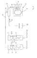
- Fig. 1 is a device 1 for storing rubber cylinder sleeves 2, which is connected to a storage device 3 connected is.
- the device 1 is designed, for example, as a magazine-like or paternoster-like warehouse or high-bay warehouse.
- the device 1 has a multiplicity of storage spaces 5, which are arranged one behind the other, one above the other and / or next to one another in the device 1, the respective storage space 5 being able to be moved to a removal and storage position 4.
- data exchange devices 6 are attached to the device 1 in a stationary manner.
- These data exchange devices 6 can be used on the rubber cylinder sleeves Read 2 memory devices 7 located and describe.
- the storage device 7 is designed as a transponder.
- the storage device 7 can, not shown in more detail, alternatively also a magnetic stripe, a memory chip or the like.
- the data storage device 3 of the device 1 is connected to a computing and storage device 8 of a first printing press 9 and to a computing and storage device 10 of a further printing press 11. Any number of storage devices and of printing presses can be connected to the storage device 3 of the device 1 via data lines 12 in order to exchange data.
- the computing and storage device 8 of the printing press 9 is via data lines 19 with data exchange devices 13 and Counter outputs 14 of individual printing units 15; 16; 17; 18 of Printing machine 9 connected.
- the computing and storage device 10 of the printing press 11 is via data lines 20 with data exchange devices 21 and Counter outputs 22 of individual printing units 23; 24; 25; 26 of Printing machine 11 connected.
- the computing and storage devices 8; 10 can be a control center, a machine control or a central computer of the Printing machine 9; Be 11.
- the storage device 3 of the device 1 in at least one of the computing and storage devices 8; 10 be integrated or through at least one of the computing and storage devices 8; 10 be replaced.
- a device for marking 39 the outsourced Rubber cylinder sleeves 2 can be arranged.
- a label can be a designation, a code or an imprint on the one to be outsourced Apply rubber cylinder sleeve 2.
- a name for the for the rubber cylinder sleeve predetermined printing unit independently from the storage device 7 to the rubber cylinder sleeve 2 muster. With the help of this name, the printing press operating printer finding the printing unit facilitated.
- the transport device 37 can also be arranged in such a way that the rubber cylinder sleeve 2 is transported from the removal and storage position 4 to the respective printing press 9; 11 and / or to the respective printing group 15 to 18; 23 to 26 can be done.
- the printing machine Before storing in the device 1, the printing machine must operating printers the damage status of the respective Assess rubber cylinder sleeve 2. The input and transmission his assessment of damage and thus the result of the Damage resulting from damage occurs from the Printing machine operating printer directly via a control panel and / or keyboard designed manual input device 27.
- the handheld input device 27 can be connected to the storage device 3 is connected to exchange data (see Fig. 2).
- Fig. 3 is a device 28 for assessment and detection the damage status of the respective rubber cylinder sleeve 2 shown. No assessment of the damage status is made here through the printer operating the press, but the Device 28 takes on the task of assessment and Registration of the damage status of the respective rubber cylinder sleeve Second
- the device 28, not shown in detail, can be electromechanical be designed device, mechanical Sensors 29 scan the surface of the rubber cylinder sleeve and these mechanical signals into electronic data 30 are converted, whereby these define the damage status electronic data 30 then the storage device 3 automatically be transmitted.
- the device 28 can also be used as an electronic one or optoelectronic (optical and electronic) Device be designed, the surface of the Rubber cylinder sleeve emitting for example by sound waves Sensors 31, for example ultrasound, or light beams emit sensors 32, for example infrared or Laser that is scanned and checked.
- the damage status defining electronic data 30 are then the Storage device 3 automatically transmitted.
- the operation of the device 1 is in the following on Process of storing a rubber cylinder sleeve and the Providing or outsourcing a rubber cylinder sleeve closer are explained.
- the printer operating the printing machine starts with a Press a button on the control center or the computing and storage device 8th; 10 of the printing press 9; 11 data exchange between the storage device arranged on the rubber cylinder sleeve 2 7 and in the printing units 15 to 18; 23 up to 26 arranged data exchange devices 13; 21 including one of the counter outputs 14; 22 to the arithmetic and storage device 8; 10 transmitted meter reading 38.
- the storage devices arranged on the rubber cylinder sleeve 2 7 are from the stationary in the individual printing units 15 to 18; 23 to 26 arranged data exchange devices 13; 21 identification data 33 transmitted and on the storage device 7 already existing characteristic data 34 read by them.
- the stationary data exchange device 13; 21 is in immediate Arranged near the storage device 7.
- the counter outputs 14; 22 of the individual printing units 15 to 18; 23 to 26 are connected to a machine control or a master computer of the machine or a computing and storage unit 8; 10, which are configured, for example, in the form of a computer.
- the data exchange devices 13; 21 are with a machine control or a host computer of the machine or a computing and storage unit 8; 10, which are configured, for example, in the form of a computer.
- the characteristic data 33 to be transmitted to the storage device 7 and characterizing the rubber cylinder sleeve 2 result from the counter outputs 14; 22 of the individual printing units 15 to 18; 23 to 26 determined information, as well as the information resulting from the printing process and from pre-programmed information resulting from the manufacture of the blanket cylinder and quality inspection.
- the characteristic data 33 are obtained from the machine control or from the master computer of the machine or the computing and storage unit 8; 10 to the data exchange device 13; 21 sent and automatically transmitted to the storage device 7.
- characteristic data 33; 34 is, for example, the identity number of the rubber cylinder sleeve 2, the designation of the rubber cylinder sleeve 2, manufacturing data, service life and operating time, errors that occurred during printing, type and number of printed images and other printing-related information, such as production information.
- the above-mentioned production information is, for example, data and information about the number of washing cycles, web width, basis weight, gross number of copies and average speed.
- Further characteristic data 33; 34 are, for example, test data, delivery data, and the first and last day of use. After the end of the service life, the reason for failure and the number of total rollovers are saved.
- the test data are to be understood as physical and geometric test values, such as stiffness values, overall thickness and material thickness of the rubber cylinder sleeve 2, as well as diameter and roughness information.
- the characteristic data thus consist of the rubber cylinder sleeve 2 individually identifying data and / or operational data, such as for example machine data.
- the rubber cylinder sleeve 2 After transfer of the characteristic data 33 to the storage device 7, the rubber cylinder sleeve 2 can be removed from the printing unit become.
- the printer operating the printing machine must now have the damage status based on damage to the surface the rubber cylinder sleeve 2.
- the data 30 about the damage status of the respective rubber cylinder sleeve 2 are from the printer operating the printing press directly via as a control panel and / or as a keyboard configured manual input device 27 into the storage device 3 entered (see Fig. 2).
- the damage status of the respective rubber cylinder sleeve 2 can be determined by means of a device 28 (see Fig. 3).
- the printer operating the printing machine lays the rubber cylinder sleeve 2 to be tested into the device 28 a, the device 28 the surface of the rubber cylinder sleeve by means of sensors 29; 31; 32 after damage checked.
- the sensors 29; 31; 32 determined information are converted into electronic data 30 and these data 30, which provide information about the damage status of the respective rubber cylinder sleeve 2, are from the device 28 automatically transferred to the storage device 3.
- the rubber cylinder sleeve 2 is now brought to the device 1 in order to be stored.
- the rubber cylinder sleeve 2 is placed on a support element 35 arranged at the removal and storage position 4 of the device 1.
- the data exchange devices 6 arranged at the removal and storage position 4 of the device 1 read out the characteristic data 34 stored on the storage device 7 of the rubber cylinder sleeve 2 and, in accordance with the identity number or designation of the rubber cylinder sleeve disclosed in these characteristic data 34, transmit the respectively associated data 30 of the damage status ,
- the characteristic data 34 read out from the storage device 7 of the rubber cylinder sleeve are transferred to the storage device 3 and stored.
- the characteristic data 33; 34 both the Rubber cylinder individually identifying data and / or the Operating data and / or data 30 about the damage status include.
- data 36 of a print job are transmitted to the storage device 3 of the device 1.
- the storage device 3 searches for a suitable rubber cylinder sleeve 2 which is embedded in the device 1 and which is suitable both for the print job and for the respective printing unit 15 to 18; 23 to 26 in accordance with the characteristic data 33; 34 of the embedded rubber cylinder sleeves 2 is suitable and fulfills the requirements resulting from the data 36.
- At the removal and storage position 4 can by means of Device for marking 39, for example a label, a designation, a code or an imprint on the outsourced Rubber cylinder sleeve 2 are applied, making a Label or a hint for that for the rubber cylinder sleeve 2 predetermined printing units 15 to 18; 23 to 26 independently from the data content of the storage device 7 to the rubber cylinder sleeve 2 can be applied. This will make the press operating printer finding this printing unit facilitated.
- the rubber cylinder sleeve 2 is in the suitable printing unit 15th to 18; 23 to 26 used.
- the printer operating the printing machine starts with a Press a button on the control center or the computing and storage device 8th; 10 of the printing press 9; 11 data exchange between the storage device arranged on the rubber cylinder sleeve 2 7 and in the printing units 15 to 18; 23 up to 26 arranged data exchange devices 13; 21 including one of the counter outputs 14; 22 to the arithmetic and storage device 8; 10 transmitted meter reading 38.
- the storage devices arranged on the rubber cylinder sleeve 2 7 are from the stationary in the individual printing units 15 to 18; 23 to 26 arranged data exchange devices 13; 21 identification data 33 transmitted and on the storage device 7 already existing characteristic data 34 read by them.
- the storage device 7 thus serves as a data carrier and as a means for data transmission and data exchange for the characteristic data 33 individually characterizing the rubber cylinder sleeve 2; 34th
- the storage device 7 also serves as a data carrier for forwarding the data from the printing press 9; 11 to the storage device 3 of the device 1.
- the storage device 7 also serves as a data carrier for forwarding the characteristic data 33 initially transmitted from the storage device 3 to the storage device 7 to the printing press 9; 11th
- the storage device 3 and of the storage device 7 the characteristic data 33 instead of by means of the stationary data exchange devices 6; 13; 21 by means of a data exchange device designed as a portable hand-held device transmitted and exchanged.
- the device 1 and the associated storage device 3 can also be used to assess print quality and wear of rubber cylinder sleeves 2 are used and should not only apply to storage and Restrict provision of rubber cylinder sleeves 2.
- the computing and / or storage device 3 of the device 1 is equipped with an interface 90 which can be tapped from an external location E 1 , the characteristic data 33; 34 and the information of the respective rubber cylinder sleeve 2 and the data and the information about the production process, the operating conditions and process data of the respective printing press 9; 11 and / or the respective printing group 15; 16; 17; 18; 23; 24; 25; 26 can be called up from external location E 1 and new characteristic data 33; 34 and information can be transmitted from the external location E 1 of the computing and / or storage device 3 (see FIG. 3).
- the data or characteristic data 33; 34 for example Manufacturing data and individually created during manufacturing Information, a new rubber cylinder sleeve 2 from Rubber cylinder sleeve manufacturers via the externally accessible Interface 90 in the computing and / or storage device 3 transmitted to the device 1 and stored there.
- the blanket cylinder manufacturer and the printing press manufacturer results from the externally accessible interface 90 the advantage that those in computing and / or Storage device 3 stored and managed characteristics 33; 34 and information about the rubber cylinder sleeves 2, the production data and the machine data to the respective Manufacturer information about the quality, about possible or real causes of failure and behavior in production of his products.
- the manufacturer On the basis of this data and information transmitted to him, the manufacturer is therefore able to improve the quality of the printing machines, printing units or rubber cylinder sleeves that have already been installed by the customer, delivered to the customer or new ones.
- the manufacturer can set up a central database that contains all of the above-mentioned characteristic data and information that are incurred or determined by the customer and transmitted via the external interface.
- Fig. 5 is a device 40 for storing rubber cylinder sleeves 41 shown with a storage device 42 is connected.
- the device 40 is designed, for example, as a magazine-like or paternoster-like warehouse or high-bay warehouse.
- the device 40 has a multiplicity of storage spaces 44 which are arranged one behind the other, one above the other and / or next to one another in the device 40, the respective storage space 44 being able to be moved to a removal and storage position 43.
- data readers 45 are attached to the device 1 in a stationary manner. With these data readers 45, storage devices 46 located on the rubber cylinder sleeves 41 can be read.
- the storage device 46 is designed as a transponder.
- the storage device 46 alternatively not shown, can alternatively also be a magnetic strip, a memory chip or the like.
- an identification 79 can be attached to the rubber cylinder sleeve 41.
- the marking 79 can be burned into the inside of the rubber cylinder sleeve 41 or be some other inscription or marking, for example in the form of a bar code, which is arranged on the surface or on one of the end faces of the rubber cylinder sleeve 41.
- the data reading device 45 is then configured, for example, as a scanner 80. With this scanner 80, the respective identification 79 can be recognized and the information coded by the identification 79, for example the identity number of the rubber cylinder sleeve, can be read.
- markings 79 are used that are not mechanical Data reader, for example data reader 45 or the scanner 80, are readable or recognizable, then are on respective printing units 54 to 57; 62 to 65 and on the device 40 input devices 82; 83 arranged.
- the the Printing machine-operated printer can be operated by means of the input devices 82; 83 applied to the rubber cylinder sleeve 41 Enter marking 79 manually.
- the data readers 45 can alternatively also be used as data exchange devices be designed, with these data exchange devices reading and writing of storage devices 46 is possible.
- the data storage device 42 of the device 40 is connected to a computing and storage device 47 of a first printing press 48 and to a computing and storage device 49 of a further printing press 50. Any number of storage devices and any number of printing presses can be connected to the storage device 42 of the device 40 via data lines 51 to exchange data.
- the computing and storage device 47 of the printing press 48 is connected via data lines 58 to data readers 52 and counter outputs 53 of the individual printing units 54; 55; 56; 57 of the printing press 48 connected.
- the computing and storage device 49 of the printing press 50 is connected via data lines 59 to data readers 60 and counter outputs 61 of the individual printing units 62; 63; 64; 65 of the printing press 50 connected.
- the data readers 52; 60 can alternatively also be used as data exchange devices be designed, with these data exchange devices reading and writing of storage devices 46 is possible.
- the computing and storage devices 47; 49 can one Control center, a machine control or a central computer printing machine 48; Be 50.
- the storage device 42 of the device 40 in at least one of the Computing and storage devices 47; 49 be integrated or by at least one of the computing and storage devices 47; 49 to be replaced. All computing and storage devices 42; 47; 49 can also function as a storage unit 81 be executed.
- a label can be a label, a code or an imprint on the Apply rubber cylinder sleeve 41 to be removed. So is a designation for the predetermined for the rubber cylinder sleeve Printing unit regardless of the example in the Storage device 46 data-stored identity number the rubber cylinder sleeve 41 on this rubber cylinder sleeve 41 can be applied. By means of this from the device for the designation 78 applied the Printing machine operating printer finding the predetermined and clearly on the label or label identifiable printing unit easier.
- the transport device 76 can be arranged in such a way that the rubber cylinder sleeve 41 is transported from the removal and storage position to the respective printing press 48; 50 and / or to the respective printing unit 54 to 57; 62 to 65 can be done.
- the transport device 76 can also be used to transport the rubber cylinder sleeve 41 from the respective printing press 48; 50 and / or from the respective printing unit 54 to 57; 62 to 65 to the device 1 or to the removal and storage position 43 of the device 1.
- the printing machine Before being stored in the device 40, the printing machine must be operating printers the damage status of the respective Assess rubber cylinder sleeve 41. The input and transmission his assessment of damage and thus the The damage status resulting from the damage takes place from the printer using the printer directly via a Control panel and / or keyboard designed manual input device 66.
- the handheld input device 66 can be used with the storage device 42 be connected to exchange data (see FIG. 5).
- FIG. 6 shows a device 67 for assessing and recording the damage status of the respective rubber cylinder sleeve 41.
- the damage status is not assessed by the printer operating the printing press, but the device 67 takes over this task.
- the device 67 can be an electromechanically designed device, mechanical sensors 68 scanning the surface of the rubber cylinder sleeve and converting these mechanical signals into electronic data 69, these electronic data 69 defining the damage status then being automatically transmitted to the storage device 42.
- the device 67 can also be configured as an electronic or optoelectronic (optical and electronic) device, the surface of the rubber cylinder sleeve 41 being scanned and checked, for example, by sensors 70 emitting sound waves, for example ultrasound, or sensors 71 emitting light rays, for example infrared or laser becomes.
- the electronic data 69 defining the damage status is then automatically transmitted to the storage device 42 again.
- the mode of operation of the device 40 is described below on the process of storing a rubber cylinder sleeve and the Providing or outsourcing a rubber cylinder sleeve closer are explained.
- the printer operating the printing machine starts by pressing a button on the control center or the computing and storage device 47; 49 of the printing press 48; 50 the data exchange between the computing and storage device 47; 49 and the storage device 42.
- characteristic data 72 of the respective ones in the printing units 54 to 57; 62 to 65 located rubber cylinder sleeve 41 including an identity number 73 applied to the storage device 46 of the rubber cylinder sleeve and including one of the counter outputs 53; 61 to the computing and storage device 47; 49 transmitted counter reading 77 from the computing and storage device 47; 49 transmitted to the storage device 42.
- the storage device 46 arranged on the rubber cylinder sleeve 41 is stationary in the individual printing units 54 to 57; 62 to 65 arranged data readers 52; 60 read the identity number 73.
- the stationary data reader 52; 60 is arranged in the immediate vicinity of the storage device 46.
- the counter outputs 53; 61 of the individual printing units 54 to 57; 62 to 65 are with a machine control or a master computer the machine or a computing and storage unit 47; 49, for example in the form of a computer are connected.
- the data readers 52; 60 are with a machine control or a master computer of the machine or a computing and Storage unit 47; 49, for example in the form of a Computers are designed, connected.
- the under the storage devices 42; 47; 49 to be exchanged or to be transmitted characterizing the rubber cylinder sleeve 41 Characteristic data 72 result from the counter outputs 53; 61 of the individual printing units 54 to 57; 62 to 65 determined information, as well as from the printing process resulting information, for example operational data and machine data.
- the characteristic data 72 are from the machine control or from the master computer of the machine or the computing and storage unit 47; 49 automatically to the storage device 42 transmitted.
- the characteristic data 72 are, for example Identity number 73 of the rubber cylinder sleeve 41, the designation the rubber cylinder sleeve 41, manufacturing data, service life and operating time, during the printing operation Errors, type and number of print images and other printing technology Marginal information, such as production information.
- the above-mentioned production information is, for example, data and information about the number of washing cycles, web width, basis weight, gross number of copies and average speed.
- Further characteristic data 72 are, for example, test data, delivery data and the first and last day of use. After the end of the service life, the reason for failure and the number of total rollovers are saved.
- the test data are to be understood as physical and geometric test values, such as, for example, stiffness values, total thickness and material thickness of the rubber cylinder sleeve 41, as well as diameter and roughness information.
- the rubber cylinder sleeve 41 can be removed from the printing unit.
- the printer operating the printing machine must now determine the damage status on the basis of damage occurring on the surface of the rubber cylinder sleeve 41.
- the data 69 about the damage status of the respective rubber cylinder sleeve 41 are operated by the printing press Printer directly via as a control panel and / or as a keyboard configured manual input device 66 into the storage device 42 entered (see Fig. 5).
- the manual input device 66 can also, not shown in more detail with one of the computing and storage devices 47; 49 connected , the data 69 on the damage status of the respective computing and storage device 47; 49 on the Storage device 42 are transferred.
- the damage status of the respective rubber cylinder sleeve 41 can be determined by means of a device 67 (see Fig. 6).
- the printer operating the printing machine lays the rubber cylinder sleeve 41 to be tested into the device 67 a, the device 67 the surface of the rubber cylinder sleeve 41 by means of sensors 68; 70; 71 after damage checked.
- the sensors 68; 70; 71 determined information are converted into electronic data 69 and this data 69, the information about the damage status of the give each rubber cylinder sleeve 41, are from the Device 67 automatically into storage device 42 transfer.
- the rubber cylinder sleeve 41 is now brought to the device 40 in order to be stored.
- the rubber cylinder sleeve 41 is placed on a support element 74 arranged at the removal and storage position 43 of the device 40.
- the data readers 45 arranged at the removal and storage position 43 of the device 40 read out the identity number 73 stored on the storage device 46 of the rubber cylinder sleeve 41 and transmit it to the storage device 42.
- Number 73 is searched there for the stored characteristic data 72 and the respectively associated data 69 of the damage status are added to this characteristic data 72.
- the rubber cylinder sleeve 41 is then stored in an unoccupied storage space 44 which was previously brought to the removal and storage position 43.
- the storage location 44 is stored with the previously read out identity number 73 for the characteristic data 72 already stored in the storage device 42.
- the characteristic data 72 of the rubber cylinder sleeve 41 embedded in the device 40 are thus updated and stored in the storage device 42.
- the characteristic data 72 stored and retrievable in the storage device 42 thus include, in addition to specifying the storage location 44, the data 69 of the damage status, data individually identifying the rubber cylinder sleeve and operating data.
- the ones stored and retrievable in the storage device 42 the characteristic data 72 characterizing the rubber cylinder sleeve 41 result from the counter outputs 53; 61 of each Printing units 54 to 57; 62 to 65 determined information, as well as the information resulting from the printing process, for example operating data and machine data.
- the characteristics resulting from the printing process for example operating data and machine data.
- the storage space 44 can additionally on the storage device 46 of the rubber cylinder sleeve 41 can be saved.
- data 75 of a print job are transmitted to the storage device 42 of the device 40.
- the storage device 42 searches for a suitable rubber cylinder sleeve 41 which is embedded in the device 40 and which is suitable both for the print job and for the respective printing unit 54 to 57; 62 to 65 is suitable according to the characteristic data 72 of the stored rubber cylinder sleeves 41 stored in the storage device 42 and fulfills the requirements resulting from the data 75.
- No suitable used rubber cylinder sleeve 41 is available Is available, so it is stored in the device 40 new rubber cylinder sleeve that has not yet been used in production 41 selected by the storage device 42.
- Rubber cylinder sleeve 41 containing storage space 44 to the and storage position 43 become those in the storage device 42 stored characteristic data 72 of the rubber cylinder sleeve 41 of the computing and storage device 47; 49 of each Printing machine 48; 50 forwarded.
- Identification device 78 for example a label, a designation, a code or an imprint on the to be provided and outsourced rubber cylinder sleeve 41 applied with what a designation or an indication for that predetermined for the use of the rubber cylinder sleeve 41 Printing unit 54 to 57; 62 to 65 regardless of the data content of the Storage device 46 can be applied to the rubber cylinder sleeve 41 is. This will serve the operator of the printing press Finding the printer for the use of the rubber cylinder sleeve 41 predetermined printing unit 54 to 57; 62 to 65 facilitated.
- the rubber cylinder sleeve 41 is in the suitable printing unit 54th to 57; 62 to 65 used.
- the printer operating the printing machine starts with a Press a button on the control center or the computing and storage device 47; 49 of the printing press 48; 50 the data exchange between the storage device 42 and the computing and Storage device 47; 49.
- the identity number 73 of the Rubber cylinder sleeve 41 is from the storage device 46 of the Rubber cylinder sleeve 41 of those in the printing units 54 to 57; 62 to 65 arranged data readers 52; 60 read and including one of the counter outputs 53; 61 transmitted counter reading 77 to the computing and storage device 47; 49 and / or to the storage device 42 forwarded.
- the storage device 46 can thus act as a data carrier and Data exchange for the rubber cylinder sleeve 41 individually characteristic 72 serve.
- the causes of failure can be identified using these characteristic data 72 Determine rubber cylinder sleeves 41 and thus enables one Assessment basis for the individual manufacturing methods or other manufacturing data of rubber cylinder sleeves 41.
- Identification number 73 cannot be shown in detail instead of using the stationary data readers 45; 52; 60 by means of a portable handheld device Read data reader and to the computing and storage device 47; 49 or storage device 42 is transmitted become.
- the device 40 and the associated storage device 42 can also be used to assess print quality and wear of rubber cylinder sleeves 41 used are and should not only be applied to storage and the provision of rubber cylinder sleeves 41.
- the computing and / or storage device 42 of the device 40 is equipped with an interface 91, which can be tapped from an external location E 2 , the characteristic data 72 and the information of the respective rubber cylinder sleeve 41 and the data and information about the production process, the operating conditions and process data of the respective printing press 48; 50 and / or the respective printing unit 54; 55; 56; 57; 62; 63; 64; 65 can be called up from external location E 2 and new characteristic data 72 and information can be transmitted from external location E 2 to computing and / or storage device 42 (see FIG. 6).
- the data or characteristic data 72 for example Manufacturing data and individually created during manufacturing Information, a new rubber cylinder sleeve 41 dated Rubber cylinder sleeve manufacturers via the externally accessible Interface 91 in the computing and / or storage device 42 transmitted to the device 40 and stored there become.
- the advantage of the externally accessible interface 91 for the blanket cylinder manufacturer and the printing press manufacturer is that the characteristic data 72 stored and managed in the computing and / or storage device 42 and information about the blanket cylinder sleeves 41, the production data and the machine data provide information to the respective manufacturer the quality, about possible or real causes of failure and about the behavior in the production use of his products. On the basis of this data and information transmitted to him, the manufacturer is therefore able to improve the quality of the printing machines, printing units or rubber cylinder sleeves that have already been installed by the customer, delivered to the customer or new ones.
- FIG. 7 shows a rubber cylinder sleeve 2 'which has a carrier sleeve 84, on which a rubber layer 85 is vulcanized or glued.
- the rubber layer 85 is advantageously designed to be compressible and, not shown in more detail, can consist of several different layers and / or materials. Such a coating is shown for example in EP 0 819 550 A2.
- the rubber layer 85 does not have one on its surface Cover layer shown in more detail with that in the offset printing process can be printed.
- a metal sleeve for example, is preferably used as the carrier sleeve 84 made of nickel, steel or aluminum, or one Plastic sleeve, for example made of carbon fiber plastic, used.
- An electronic storage device 7 ′ designed as a transponder is arranged in an edge region of the rubber layer 85, preferably in a non-printing region of the rubber layer 85.
- the storage device 7 ′ alternatively not shown, can alternatively also be a magnetic strip, a memory chip or the like.
- the transponder 7 ' is advantageously embedded in the rubber layer 85, that is to say it is surrounded on all sides by the material of the rubber layer 85, so that optimal protection for the transponder 86 is ensured.
- the transponder 7 ' can be arranged on the edge region of the rubber layer 85 such that one side of the transponder 86 is not surrounded by the rubber layer and is therefore exposed. Both the outside and the inside of the rubber cylinder sleeve 2 'are designed free of elevations.
- the edge area of the rubber layer 85 is often a few tenths of a millimeter deeper than the rest of the rubber layer 85. In this edge area exposed to less stress the transponder 7 'is advantageously arranged.
- the transponder 7 ' are transferred from a data exchange device 6'; 13 '; 21 'characteristic data 33' are transmitted and characteristic data 34 'already present on the transponder 7' are read by the latter.
- the stationary data exchange device 6 '; 13 '; 21 ' is arranged in the immediate vicinity of the transponder 7'.
- the data exchange device 6 '; 13 '; 21 ' is with a machine control or a host computer of the machine or a computing and storage unit 3';8th'; 10 ', for example a separate evaluation unit in the form of a computer.
- the characteristic data 33 ' are from the machine control or from the master computer of the machine or the computing and storage unit 3 '; 8th'; 10 'to the data exchange device 6 '; 13 '; 21 'sent and automatically to the transponder 7' transmitted.
- the characteristic data 33 ' are either entered directly into the machine control system by the operator via a control panel and / or a keyboard, or are determined by the machine control system itself.
- the characteristic data 33 '; 34 ' is, for example, manufacturing data, service life and operating time, errors which occurred during printing, number of rollovers, type and number of printed images and other printing-related information.
- the characteristics of the transponder 7 ' cannot be shown 33 '; 34 'instead of by means of the stationary arrangement Data exchange device 6 '; 13 '; 21 'by means of a portable Handheld data exchange device transmitted and be exchanged.
- transponder 7 'and the data exchange device 6 '; 13 '; 21 ' also for the assessment of manufacturing methods, Print quality and wear used in blankets are and should not only apply to the application Limit rubber cylinder sleeves.
- the arrangement of the transponder 7 'on the rubber-coated area of the carrier sleeve is not absolutely necessary.
- the transponder 7 ' can be arranged, for example, on the end faces of the rubber layer 85, the transponder 7' being glued on with a seal designed as an adhesive, which serves to seal the end faces of the rubber layer 85. This means that the transponder 7 'or any other storage device can be glued on subsequently in the printing house.
- the transponder 7 'or any other storage device can attached at any point on the rubber cylinder sleeve 2 ' be, the transponder 7 'by means of a Adhesive tape made fastener on the rubber cylinder sleeve 2 'is attachable.
- the transponder 7 'or the storage device listed self-adhesive or self-attaching his.
- the transponder 7 'or the storage device cannot also shown in more detail in the metal layer of the carrier sleeve 84 embedded or arranged on the metal layer 84 and / or be attached.
Landscapes
- Engineering & Computer Science (AREA)
- Mechanical Engineering (AREA)
- Inking, Control Or Cleaning Of Printing Machines (AREA)
- Rotary Presses (AREA)
- Printing Plates And Materials Therefor (AREA)
- Manufacture Or Reproduction Of Printing Formes (AREA)
- Dry Development In Electrophotography (AREA)
Abstract
Description
Mit diesem Speicherbaustein ist eine elektronisch gespeicherte hülsenindividuelle Kennzeichnung möglich, wobei diese Kennzeichnung beispielsweise eine fortlaufende Seriennummer, Herstellungsdatum, Abmessungen und Werkstoffe der Hülse und/oder das vom Kunden auf die Hülse aufgebrachte Motiv oder eine Angabe über den Endabnehmer ist.
Des weiteren können in dem elektronischen Speicherbaustein die oben genannten Informationen zumindest teilweise überschreiben und aktualisiert werden.
Das Überschreiben und Abfragen dieser Informationen erfolgt bei Stillstand der Maschine oder an aus der Maschine herausgenommenen Druck-Hülsen.
Zur Kostenminimierung besteht in den Druckereien der Bedarf bereits benutzte und für den jeweiligen Druckvorgang geeignete Hülsen, insbesondere Gummizylinderhülsen, zu verwenden. Ein genaues Auffinden einer derartigen für den Druckvorgang geeigneten "gebrauchten", d.h. bereits ein oder mehrmals verwendeten, Hülse im Lager ist jedoch mühsam und zeitaufwendig.
Darüber hinaus wird durch die Vorrichtung eine organisierte Lagerhaltung von Gummizylinderhülsen geschaffen.
In diese Speichervorrichtung werden sowohl permanent, als auch kurzzeitig zu verwaltende Informationen und Kenndaten abgelegt.
Die oben genannten Produktionsinformationen sind beispielsweise Daten und Informationen über die Anzahl der Waschzyklen, Bahnbreite, Flächengewicht, Bruttoexemplarzahl, mittlere Drehzahl.
Die elektronische Speichervorrichtung kann aber auch beispielsweise ein Magnetstreifen, ein Speicherchip oder dergleichen sein.
Die Anordnung des Transponders erfolgt dabei nicht zwingend auf dem gummibeschichteten Bereich der Trägerhülse. Die Anordnung des Transponders kann beispielsweise an den Stirnseiten der Gummischicht erfolgen, wobei der Transponder mit einer als Klebemittel ausgeführten Versiegelung, die zur Versiegelung der Stirnseiten der Gummischicht dient, aufgeklebt wird. Der Transponder oder jede andere Speichervorrichtung kann an jeder beliebigen Stelle der Gummizylinderhülse angebracht werden, wobei der Transponder mittels eines als Klebeband ausgeführten Befestigungsmittels an der Gummizylinderhülse befestigbar ist. Vorteilhafterweise kann der Transponder oder die Speichervorrichtung selbstklebend oder sich selbstbefestigend aufgeführt sein.
Somit ist das Aufkleben des Transponders oder jeder anderen Speichervorrichtung in der Druckerei möglich.
Es ist auch möglich, dass an der Gummizylinderhülse ein zusätzliches Element oder zusätzliches Mittel oder eine Verlängerung der Gummizylinderhülse anordbar und befestigbar ist, an oder auf welchem der Transponder oder die Speichervorrichtung anordbar und/oder befestigt ist.
Der Transponder kann auch auf der Trägerhülse aufgesetzt oder in die Trägerhülse eingelassen oder eingebettet sein, wobei hier die Trägerhülse aus Kunststoffen oder Verbundwerkstoffen, beispielsweise Faserverbundwerkstoffe wie Carbonfaser-Kunststoffe (CFK), besteht.
Es ist somit ein spontaner Abruf und Zugriff aller für einen Produktionsablauf wichtiger auf die Gummizylinderhülse bezogener Daten, wie Kenndaten, Betriebsdaten und Druckmaschinendaten, ermöglicht.
Erwähnenswert ist, dass mittels der Vorrichtung Kosten, insbesondere Personalkosten, eingespart werden, da nicht mehr der die Druckmaschine bedienende Drucker, sondern die Vorrichtung zur Einlagerung eine zum jeweiligen Druckauftrag passende Gummizylinderhülse automatisiert aufsucht und bereitstellt.
Hierzu werden spezielle zum Datenauslesen auf die jeweilige Kennzeichnung abgestimmte Datenlesegeräte verwendet.
Somit können die Daten, beispielsweise Herstellungsdaten und individuell bei der Herstellung entstehende Informationen, einer neuen Gummizylinderhülse vom Gummizylinderhülsenhersteller über die extern zugängliche Schnittstelle in die Rechen- und/oder Speichervorrichtung der Vorrichtung zur Einlagerung übermittelt und dort abgespeichert werden.
Die Vorrichtung 1 weist eine Vielzahl von Lagerplätzen 5 auf, die hintereinander, überanander und/oder nebeneinander in der Vorrichtung 1 angeordnet sind, wobei der jeweilige Lagerplatz 5 an eine Aus- und Einlagerungsposition 4 verbringbar ist. Im Bereich der Aus- und Einlagerungsposition 4 sind Datenaustauschgeräte 6 stationär an der Vorrichtung 1 angebracht.
Mit der Speichervorrichtung 3 der Vorrichtung 1 kann eine beliebige Anzahl von Speichervorrichtungen und von Druckmaschinen über Datenleitungen 12 datenaustauschend verbunden sein.
Die Transportvorrichtung 37 kann auch derart angeordnet sein, dass ein Transport der Gummizylinderhülse 2 von der Aus- und Einlagerungsposition 4 zur jeweiligen Druckmaschine 9; 11 und/oder zum jeweiligen Druckwerk 15 bis 18; 23 bis 26 erfolgen kann.
Die Datenaustauschgeräte 13; 21 sind mit einer Maschinensteuerung oder einem Leitrechner der Maschine oder einer Rechen- und Speichereinheit 8; 10, die beispielsweise in Form eines Computers ausgestaltet sind, verbunden.
Die Kenndaten 33 werden von der Maschinensteuerung oder von dem Leitrechner der Maschine oder der Rechen- und Speichereinheit 8; 10 an das Datenaustauschgerät 13; 21 gesendet und automatisch an die Speichervorrichtung 7 übermittelt.
Die oben genannten Produktionsinformationen sind beispielsweise Daten und Informationen über die Anzahl der Waschzyklen, Bahnbreite, Flächengewicht, Bruttoexemplarzahl und mittlere Drehzahl.
Weitere Kenndaten 33; 34 sind beispielsweise Prüfdaten, Lieferdaten, sowie erster und letzter Einsatztag. Nach Lebensdauerende wird der Ausfallgrund und die Anzahl der Gesamtüberrollungen abgespeichert.
Unter den Prüfdaten sind physikalische und geometrische Testwerte, wie beispielsweise Steifigkeitswerte, Gesamtdicke und Materialstärke der Gummizylinderhülse 2, sowie Durchmesser und Rauhigkeitsangaben zu verstehen.
Die an der Aus- und Einlagerungsposition 4 der Vorrichtung 1 angeordneten Datenaustauschgeräte 6 lesen die auf der Speichervorrichtung 7 der Gummizylinderhülse 2 gespeicherten Kenndaten 34 aus und übermitteln gemäß der in diesen Kenndaten 34 offenbarten Identitäts-Nummer oder Bezeichnung der Gummizylinderhülse die jeweils dazugehörenden Daten 30 des Schadenstatus. Die aus der Speichervorrichtung 7 der Gummizylinderhülse ausgelesenen Kenndaten 34 werden in die Speichervorrichtung 3 übertragen und abgespeichert.
Aus diesen Daten 36 sucht die Speichervorrichtung 3 eine geeignete in der Vorrichtung 1 eingelagerte Gummizylinderhülse 2, welche sowohl für den Druckauftrag, als auch für das jeweilige Druckwerk 15 bis 18; 23 bis 26 gemäß der in der Speichervorrichtung 3 abgespeicherten Kenndaten 33; 34 der eingelagerten Gummizylinderhülsen 2 geeignet ist und die gestellten aus den Daten 36 sich ergebenden Anforderungen erfüllt.
Darüber hinaus dient die Speichervorrichtung 7 auch als Datenträger zur Weiterleitung der zunächst von der Druckmaschine 9; 11 auf die Speichervorrichtung 7 übermittelten Kenndaten 33 an die Speichervorrichtung 3 der Vorrichtung 1. Umgekehrt dient die Speichervorrichtung 7 auch als Datenträger zur Weiterleitung der zunächst von der Speichervorrichtung 3 auf die Speichervorrichtung 7 übermittelten Kenndaten 33 an die Druckmaschine 9; 11.
Darüber hinaus kann der Hersteller sich eine zentrale Datenbank aufbauen, welche alle beim Kunden anfallende bzw. ermittelte und über die externe Schnittstelle übermittelte oben genannten Kenndaten und Informationen enthält.
Die Vorrichtung 40 weist eine Vielzahl von Lagerplätzen 44 auf, die hintereinander, überanander und/oder nebeneinander in der Vorrichtung 40 angeordnet sind, wobei der jeweilige Lagerplatz 44 an eine Aus- und Einlagerungsposition 43 verbringbar ist. Im Bereich der Aus- und Einlagerungsposition 43 sind Datenlesegeräte 45 stationär an der Vorrichtung 1 angebracht.
Mit diesen Datenlesegeräten 45 lassen sich an den Gummizylinderhülsen 41 befindliche Speichervorrichtungen 46 lesen.
Die Speichervorrichtung 46 ist als Transponder ausgestaltet. Die Speichervorrichtung 46 kann, nicht näher dargestellt, alternativ auch ein Magnetstreifen, ein Speicherchip oder dergleichen sein.
Das Datenlesegerät 45 ist in diesem Falle dann beispielsweise als Scanner 80 ausgestaltet. Mit diesem Scanner 80 ist die jeweilige Kennzeichnung 79 erkennbar und die durch die Kennzeichnung 79 codierte Information, beispielsweise die Identitäts-Nummer der Gummizylinderhülse, lesbar.
Mit der Speichervorrichtung 42 der Vorrichtung 40 kann eine beliebige Anzahl von Speichervorrichtungen und beliebige Anzahl von Druckmaschinen über Datenleitungen 51 datenaustauschend verbunden sein.
Die Rechen- und Speichervorrichtung 49 der Druckmaschine 50 ist über Datenleitungen 59 mit Datenlesegeräten 60 und Zählerausgängen 61 der einzelnen Druckwerke 62; 63; 64; 65 der Druckmaschine 50 verbunden.
Mit der Transportvorrichtung 76 kann auch ein Transport der Gummizylinderhülse 41 von der jeweiligen Druckmaschine 48; 50 und/oder vom jeweiligen Druckwerk 54 bis 57; 62 bis 65 zur Vorrichtung 1 oder zur Aus- und Einlagerungsposition 43 der Vorrichtung 1 erfolgen.
Die Vorrichtung 67 kann, nicht näher dargestellt, eine elektromechanisch ausgestaltete Vorrichtung sein, wobei mechanische Sensoren 68 die Oberfläche der Gummizylinderhülse abtasten und diese mechanischen Signale in elektronische Daten 69 umwandelt, wobei diese den Schadenstatus definierenden elektronischen Daten 69 dann der Speichervorrichtung 42 automatisch übermittelt werden.
Alternativ kann die Vorrichtung 67 auch als eine elektronische oder optoelektronische (optische und elektronische) Vorrichtung ausgestaltet sein, wobei die Oberfläche der Gummizylinderhülse 41 beispielsweise durch Schallwellen aussendenden Sensoren 70, beispielsweise Ultraschall, oder Lichtstrahlen aussenden Sensoren 71, beispielsweise Infrarot oder Laser, abgetastet und überprüft wird. Die den Schadenstatus definierenden elektronischen Daten 69 werden dann wieder der Speichervorrichtung 42 automatisch übermittelt.
Zum Datenaustausch werden Kenndaten 72 der jeweiligen in den Druckwerken 54 bis 57; 62 bis 65 befindlichen Gummizylinderhülse 41 unter Einbeziehung einer auf der Speichervorrichtung 46 der Gummizylinderhülse aufgebrachten Identitäts-Nummer 73 und unter Einbeziehung eines von den Zählerausgängen 53; 61 an die Rechnen- und Speichervorrichtung 47; 49 übermittelten Zählerstandes 77 von der Rechen- und Speichervorrichtung 47; 49 an die Speichervorrichtung 42 übermittelt.
Das stationäre Datenlesegerät 52; 60 ist in unmittelbarer Nähe der Speichervorrichtung 46 angeordnet.
Weitere Kenndaten 72 sind beispielsweise Prüfdaten, Lieferdaten, sowie erster und letzter Einsatztag. Nach Lebensdauerende wird der Ausfallgrund und die Anzahl der Gesamtüberrollungen abgespeichert.
Unter den Prüfdaten sind physikalische und geometrische Testwerte, wie beispielsweise Steifigkeitswerte, Gesamtdicke und Materialstärke der Gummizylinderhülse 41, sowie Durchmesser und Rauhigkeitsangaben zu verstehen.
Der die Druckmaschine bedienende Drucker muß nun den Schadenstatus anhand von auftretenden Beschädigungen an der Oberfläche der Gummizylinderhülse 41 ermitteln.
Die an der Aus- und Einlagerungsposition 43 der Vorrichtung 40 angeordneten Datenlesegeräte 45 lesen die auf der Speichervorrichtung 46 der Gummizylinderhülse 41 gespeicherte Identitäts-Nummer 73 aus und übermittelen diese der Speichervorrichtung 42. In der Speichervorrichtung 42 wird gemäß der von der einzulagernden Gummizylinderhülse 41 eingelesenen Identitäts-Nummer 73 dort nach den abgespeicherten Kenndaten 72 gesucht und die jeweils dazugehörenden Daten 69 des Schadenstatus zu diesen Kenndaten 72 hinzugefügt.
Anschließend wird die Gummizylinderhülse 41 in einen unbesetzten Lagerplatz 44 eingelagert, der vorher an die Aus- und Einlagerungsposition 43 verbracht wurde. Der Lagerplatz 44 wird mit der zuvor ausgelesenen Identitäts-Nummer 73 zu den in der Speichervorrichtung 42 bereits abgelegten Kenndaten 72 abgespeichert.
Somit sind die Kenndaten 72 der in die Vorrichtung 40 eingelagerten Gummizylinderhülse 41 in der Speichervorrichtung 42 aktualisiert und abgespeichert. Die in der Speichervorrichtung 42 abgespeicherten und abrufbaren Kenndaten 72 umfassen also neben der Angabe des Lagerplatzes 44 die Daten 69 des Schadenstatus, die Gummizylinderhülse individuell kennzeichnende Daten und Betriebsdaten.
Aus diesen Daten 75 sucht die Speichervorrichtung 42 eine geeignete in der Vorrichtung 40 eingelagerte Gummizylinderhülse 41, welche sowohl für den Druckauftrag, als auch für das jeweilige Druckwerk 54 bis 57; 62 bis 65 gemäß der in der Speichervorrichtung 42 abgespeicherten Kenndaten 72 der eingelagerten Gummizylinderhülsen 41 geeignet ist und die gestellten aus den Daten 75 sich ergebenden Anforderungen erfüllt.
Eine derartige Bestellung kann auch vom Leitstand, dem zentralen Rechner oder der Rechen- und Speichervorrichtung 47; 49 der Druckmaschine 48; 50 ausgelöst werden.
Der Hersteller ist somit auf Grund dieser ihm übermittelten Daten und Informationen in der Lage, Qualitätsverbesserungen an den beim Kunden bereits aufgestellten, an zum Kunden ausgelieferten oder auch an neuen Druckmaschinen, Druckwerken oder Gummizylinderhülsen vorzunehmen.
Eine derartige Beschichtung ist beispielsweise in der EP 0 819 550 A2 gezeigt.
Die Speichervorrichtung 7' kann, nicht näher dargestellt, alternativ auch ein Magnetstreifen, ein Speicherchip oder dergleichen sein.
Der Transponder 7' ist vorteilhaft in die Gummischicht 85 eingelassen, also allseitig vom Werkstoff der Gummischicht 85 umgeben, so daß ein optimaler Schutz für den Transponder 86 gewährleistet ist.
Sowohl die Außenseite als auch die Innenseite der Gummizylinderhülse 2' ist frei von Erhöhungen ausgestaltet.
Das Datenaustauschgerät 6'; 13'; 21' ist mit einer Maschinensteuerung oder einem Leitrechner der Maschine oder einer Rechen- und Speichereinheit 3'; 8'; 10', beispielsweise einer separaten Auswerteeinheit in Form eines Computers, verbunden.
Bei den Kenndaten 33'; 34' handelt es sich beispielsweise um Herstellungsdaten, Lebensdauer und Einsatzzeit, während, des Druckeinsatzes aufgetretene Fehler, Anzahl der Überrollungen, Art und Anzahl der Druckbilder und weitere drucktechnische Randinformationen.
Somit ist das Aufkleben des Transponders 7' oder jeder anderen Speichervorrichtung nachträglich in der Druckerei möglich.
- 1
- Vorrichtung
- 2
- Gummizylinderhülse
- 3
- Speichervorrichtung
- 4
- Aus- und Einlagerungsposition
- 5
- Lagerplatz
- 6
- Datenaustauschgerät
- 7
- Speichervorrichtung
- 8
- Rechen- und Speichervorrichtung
- 9
- Druckmaschine
- 10
- Rechen- und Speichervorrichtung
- 11
- Druckmaschine
- 12
- Datenleitung
- 13
- Datenaustauschgerät
- 14
- Zählerausgang
- 15
- Druckwerk
- 16
- Druckwerk
- 17
- Druckwerk
- 18
- Druckwerk
- 19
- Datenleitung
- 20
- Datenleitung
- 21
- Datenaustauschgerät
- 22
- Zählerausgang
- 23
- Druckwerk
- 24
- Druckwerk
- 25
- Druckwerk
- 26
- Druckwerk
- 27
- Handeingabegerät
- 28
- Vorrichtung zur Beurteilung des Schadenstatus
- 29
- Sensor
- 30
- Daten über den Schadenstatus
- 31
- Sensor
- 32
- Sensor
- 33
- Kenndaten
- 34
- Kenndaten
- 35
- Auflageelement
- 36
- Daten eines Druckauftrages
- 37
- Transportvorrichtung
- 38
- Zählerstand
- 39
- Vorrichtung zur Kennzeichnung
- 40
- Vorrichtung
- 41
- Gummizylinderhülse
- 42
- Speichervorrichtung
- 43
- Aus- und Einlagerungsposition
- 44
- Lagerplatz
- 45
- Datenlesegerät
- 46
- Speichervorrichtung
- 47
- Rechen- und Speichervorrichtung
- 48
- Druckmaschine
- 49
- Rechen- und Speichervorrichtung
- 50
- Druckmaschine
- 51
- Datenleitung
- 52
- Datenlesegerät
- 53
- Zählerausgang
- 54
- Druckwerk
- 55
- Druckwerk
- 56
- Druckwerk
- 57
- Druckwerk
- 58
- Datenleitung
- 59
- Datenleitung
- 60
- Datenlesegerät
- 61
- Zählerausgang
- 62
- Druckwerk
- 63
- Druckwerk
- 64
- Druckwerk
- 65
- Druckwerk
- 66
- Handeingabegerät
- 67
- Vorrichtung zur Beurteilung des Schadenstatus
- 68
- Sensor
- 69
- Daten über den Schadenstatus
- 70
- Sensor
- 71
- Sensor
- 72
- Kenndaten
- 73
- Identitäts-Nummer
- 74
- Auflageelement
- 75
- Daten eines Druckauftrages
- 76
- Transportvorrichtung
- 77
- Zählerstand
- 78
- Vorrichtung zur Kennzeichnung
- 79
- Kennzeichnung
- 80
- Scanner
- 81
- Speichereinheit
- 82
- Eingabevorrichtung
- 83
- Eingabevorrichtung
- 84
- Trägerhülse
- 85
- Gummizylinderhülsenbeschichtung
- 90
- Schnittstelle
- 91
- Schnittstelle
- 2'
- Gummizylinderhülse
- 3'
- Rechen- und Speichereinheit
- 6'
- Datenaustauschgerät
- 7'
- Speichervorrichtung
- 8'
- Rechen- und Speichereinheit
- 10'
- Rechen- und Speichereinheit
- 13'
- Datenaustauschgerät
- 21'
- Datenaustauschgerät
- 33'
- Kenndaten
- 34'
- Kenndaten
- E1; E2
- externe Stelle
Claims (55)
- Vorrichtung (1; 40) zur Einlagerung von Hülsen einer Rotationsdruckmaschine (9; 11; 48; 50), dadurch gekennzeichnet, dassa) die Vorrichtung (1; 40) mit einer elektronischen Speichervorrichtung (3; 42) ausgestattet ist, in die für jede als Gummizylinderhülse (2; 41) für Offsetdruck ausgeführte Hülse Kenndaten (34; 72) eingebbar, speicherbar und verwaltbar sind,b) die Gummizylinderhülse (2; 41) in die Vorrichtung (1; 40) einbringbar ist, wobei beim Einbringen der Gummizylinderhülse (2; 41) in die Vorrichtung (1; 40) die Kenndaten (34; 72) der Gummizylinderhülse (2; 41) in die Speichervorrichtung (3; 42) eingelesen werden,c) die Gummizylinderhülse (2; 41) nach vorgegebenen Daten (36; 75) aus der Vorrichtung (1; 40) entnehmbar ist.
- Vorrichtung nach Anspruch 1, dadurch gekennzeichnet, dass die Kenndaten (34; 72) aus die Gummizylinderhülse (2; 41) individuell kennzeichnende Daten und/oder Betriebsdaten und/oder Daten über den Schadenstatus (30; 69) bestehen.
- Vorrichtung nach Anspruch 1 oder 2, dadurch gekennzeichnet, dass die Vorrichtung (1; 40) Lagerplätze (5; 44) für die Gummizylinderhülsen (2; 41) aufweist, die nebeneinander und/oder übereinander und/oder hintereinander und/oder umlaufend und/oder verfahrbar angeordnet sind.
- Vorrichtung nach Anspruch 3, dadurch gekennzeichnet, dass der einzelne Lagerplatz (5; 44) an eine Ein- und Auslagerungsposition (4; 43) verbringbar ist.
- Vorrichtung nach insbesondere einem der Ansprüche 1 bis 4, dadurch gekennzeichnet, dass eine Kennzeichnung (79) auf der Gummizylinderhülse (41) angeordnet ist, mittels derer die Kenndaten (72) zur jeweiligen Gummizylinderhülse (41) zuordbar sind und die Kenndaten (72) beim Einlagern in die Speichervorrichtung (42) einlesbar sind.
- Vorrichtung nach insbesondere einem der Ansprüche 1 bis 4, dadurch gekennzeichnet, dass eine Identitäts-Nummer (73) auf einer elektronischen Speichervorrichtung (46) der Gummizylinderhülse (2) angeordnet ist, mittels derer die Kenndaten (72) zur jeweiligen Gummizylinderhülse (41) zuordbar sind und die Kenndaten (72) beim Einlagern der Speichervorrichtung (42) einlesbar sind.
- Vorrichtung nach Anspruch 6, dadurch gekennzeichnet, dass die Identitäts-Nummer (73) beim Einlagern von der Speichervorrichtung (46) in die Speichervorrichtung (42) einlesbar ist.
- Vorrichtung nach insbesondere einem der Ansprüche 1 bis 4, dadurch gekennzeichnet, dass die Kenndaten (72) der Gummizylinderhülse (41) auf der elektronischen Speichervorrichtung (46) abgelegt sind und die Kenndaten (72) beim Einlagern von der Speichervorrichtung (46) in die Speichervorrichtung (41) einlesbar sind.
- Vorrichtung nach insbesondere Anspruch 5 , dadurch gekennzeichnet, dass mittels eines in der Vorrichtung (40) angeordneten Datenlesegerätes (45) oder Scanners (80) die Kennzeichnung (79) in die Speichervorrichtung (3) lesbar und die zur Kennzeichnung (40) zuordbaren Kenndaten (72) und/oder geänderte Kenndaten (72) und/oder Daten (69) zwischen den Speichervorrichtungen (42; 47; 49) austauschbar und auf die jeweilige Speichervorrichtung (42; 47; 49) schreibbar und speicherbar sind.
- Vorrichtung nach insbesondere Anspruch 6 , dadurch gekennzeichnet, dass mittels eines in der Vorrichtung (40) angeordneten Datenlesegerätes (45) die Identitäts-Nummer (73) von der Speichervorrichtung (46) in die Speichervorrichtung (42) lesbar und die zur Identitäts-Nummer (73) zuordbaren Kenndaten (72) und/oder geänderte Kenndaten (72) und/oder Daten (69) zwischen den Speichervorrichtungen (46; 47; 49) austauschbar und auf die jeweilige Speichervorrichtung (46; 47; 49) schreibbar und speicherbar sind.
- Vorrichtung nach einem der Ansprüche 9 oder 10, dadurch gekennzeichnet, dass Datenlesegeräte (45; 52; 60) in und/oder an Druckwerken (54; 55; 56; 57; 62; 63; 64; 65) und der Vorrichtung (1) angeordnet sind.
- Vorrichtung nach insbesondere Anspruch 11, dadurch gekennzeichnet, dass die Datenlesegeräte (45; 52; 60) als Datenaustauschgeräte ausgestaltet sind und die Kenndaten (72) unter den Speichervorrichtungen (42; 47; 49) austauschbar und speicherbar sind.
- Vorrichtung nach insbesondere einem der Ansprüche 6, 7, 8, 10, 11 oder 12, dadurch gekennzeichent, dass die Speichervorrichtung (46) als Mittel zur Datenübertragung und zum Datenaustausch zwischen den Speichervorrichtungen (47; 49) und der Speichervorrichtung (42) dient.
- Vorrichtung nach einem der Ansprüche 6, 7, 8, 10, 11, 12 oder 13, dadurch gekennzeichnet, daß die Speichervorrichtung (7) als Transponder ausgestaltet ist.
- Vorrichtung nach einem der Ansprüche 7, 8, 10, 11, 12 oder 13, dadurch gekennzeichnet, dass das Datenablesen zwischen der Speichervorrichtung (7) und dem Datenlesegerät (45; 52; 60) berührungslos erfolgt.
- Vorrichtung nach einem der Ansprüche 1 bis 15, dadurch gekennzeichnet, dass die Speichervorrichtung (42) in mindestens eine der Rechen- und Speichervorrichtungen (47; 49) integriert ist.
- Vorrichtung nach insbesondere einem der Ansprüche 1 bis 15, dadurch gekennzeichnet, dass die Speichervorrichtung (42) und die Rechen- und Speichervorrichtungen (47; 49) in mindestens eine Speichereinheit (81) integriert ist.
- Vorrichtung nach insbesondere einem der Ansprüche 1 bis 17, dadurch gekennzeichnet, dass eine Transportvorrichtung (76) einen Transport der aus der Vorrichtung (40) entnehmbaren Gummizylinderhülse (41) zum Druckwerk (54 bis 57; 62 bis 65) und/oder der Druckmaschine (48; 50) ermöglicht.
- Vorrichtung nach insbesondere einem der Ansprüche 1 bis 18, dadurch gekennzeichnet, dass eine Vorrichtung zur Kennzeichnung (78) der entnehmbaren Gummizylinderhülsen (41) an der Vorrichtung (40) angeordnet ist.
- Vorrichtung nach insbesondere einem der Ansprüche 2 bis 19, dadurch gekennzeichnet, dass die Daten über den Schadenstatus (69) der Gummizylinderhülse (41) mittels einer Vorrichtung (67) ermittelbar sind.
- Vorrichtung nach insbesondere einem der Ansprüche 2 bis 19, dadurch gekennzeichnet, dass die Daten über den Schadenstatus (69) der Gummizylinderhülse (41) manuell von einem die Druckmaschine (48; 50) bedienenden Drucker ermittelbar und in ein Handeingabegerät (66) eingebbar sind.
- Vorrichtung nach einem der Ansprüche 20 oder 21, dadurch gekennzeichnet, dass die Daten über den Schadenstatus (69) einer der Speichervorrichtungen (42; 47; 49) übermittelbar sind.
- Vorrichtung nach insbesondere einem der Ansprüche 1 bis 22, dadurch gekennzeichnet, dass mittels der in der Speichervorrichtung (42) abgelegten Kenndaten (72) Bestellungen von neuen Gummizyllinderhülsen (41) automatisch auslös- und durchführbar sind.
- Vorrichtung nach insbesondere einem der Ansprüche 1 bis 23, dadurch gekennzeichnet, dass mittels der in der Speichervorrichtung (42) abgelegten Kenndaten (72) eine Statistik über den wahrscheinlichen Ausfall von Gummizyllinderhülsen (41) berechenbar ist.
- Verfahren zur Einlagerung von mit einer Kennzeichnung (79) ausgestatteten Hülsen, dadurch gekennzeichnet, dass Kenndaten (72) der als Gummizylinderhülsen (41) für Offsetdruck ausgestalteten Hülse von einer Rechen- und Speichervorrichtung (47; 49) einer Rotationsdruckmaschine (48; 50) einer Speichervorrichtung (42) einer Vorrichtung (40) zur Einlagerung übermittelt und dort abgespeichert werden, wobei über die Kennzeichnung (79) der Gummizylinderhülse (41) die Kenndaten (72) der jeweiligen Gummizylinderhülse (41) zugeordnet werden.
- Vorrichtung nach insbesondere einem der Ansprüche 1 bis 4, dadurch gekennzeichnet, dass die Kenndaten (34) der Gummizylinderhülse (2) auf einer elektronischen Speichervorrichtung (7), die auf der Gummizylinderhülse (2) angeordnet ist, abgelegt sind und beim Einlagern von der Speichervorrichtung (7) in die Speichervorrichtung (3) einlesbar sind.
- Vorrichtung nach insbesondere Anspruch 26 , dadurch gekennzeichnet, dass mittels eines in der Vorrichtung (1) angeordneten Datenaustauschgerätes (6) die Kenndaten (34) von der Speichervorrichtung (7) in die Speichervorrichtung (3) lesbar und neue Kenndaten (33) und/oder geänderte Kenndaten (33) und/oder Daten (30) von der Speichervorrichtung (3) auf die Speichervorrichtung (7) schreibbar und speicherbar sind.
- Vorrichtung nach insbesondere einem der Ansprüche 26 oder 27 , dadurch gekennzeichnet, dass mittels eines in Druckwerken (15 bis 18; 23 bis 26) angeordneten Datenaustauschgerätes (13; 21) die Kenndaten (34) von der Speichervorrichtung (7) in eine Rechen- und Speichervorrichtung (8; 10) lesbar und neue Kenndaten (33) und/oder geänderte Kenndaten (33) von der Rechen- und Speichervorrichtung (8; 10) auf die Speichervorrichtung (7) schreibbar und speicherbar sind.
- Vorrichtung nach insbesondere einem der Ansprüche 26 bis 28, dadurch gekennzeichent, dass die Speichervorrichtung (7) als Mittel zum Bewerkstelligen eines Datenaustausch zwischen den Druckwerken (15 bis 18; 23 bis 26) und der Vorrichtung (1) dient, wobei der Datenaustausch mittels der Speichervorrichtung (7) zwischen der Rechen- und Speichervorrichtung (8; 10) und der Speichervorrichtung (3) erfolgt.
- Vorrichtung nach einem der Ansprüche 26 bis 29, dadurch gekennzeichnet, daß die Speichervorrichtung (7) als Transponder ausgestaltet ist.
- Vorrichtung nach einem der Ansprüche 27 bis 30, dadurch gekennzeichnet, dass der Datenaustausch zwischen der Speichervorrichtung (7) und dem Datenaustauschgerät (6; 13; 21) berührungslos erfolgt.
- Vorrichtung nach insbesondere einem der Ansprüche 1 bis 4 oder 26 bis 31, dadurch gekennzeichnet, dass die Speichervorrichtung (3) in mindestens eine der Rechen- und Speichervorrichtungen (8; 10) integriert ist.
- Vorrichtung nach insbesondere einem der Ansprüche 1 bis 4 oder 26 bis 32, dadurch gekennzeichnet, dass eine Transportvorrichtung (37) einen Transport der aus der Vorrichtung (1) entnehmbaren Gummizylinderhülse (2) zum Druckwerk (15 bis 18; 23 bis 26) und/oder der Druckmaschine (9; 11) ermöglicht.
- Vorrichtung nach insbesondere einem der Ansprüche 1 bis 4 oder 26 bis 33, dadurch gekennzeichnet, dass eine Vorrichtung zur Kennzeichnung (39) der entnehmbaren Gummizylinderhülsen (2) an der Vorrichtung (1) angeordnet ist.
- Vorrichtung nach insbesondere einem der Ansprüche 1 bis 4 oder 26 bis 34, dadurch gekennzeichnet, dass Daten über den Schadenstatus (30) der Gummizylinderhülse (2) mittels einer Vorrichtung (28) ermittelbar sind, wobei die Daten über den Schadenstatus (30) einer der Speichervorrichtungen (3; 8; 10) übermittelt werden.
- Vorrichtung nach insbesondere einem der Ansprüche 1 bis 4 oder 26 bis 34, dadurch gekennzeichnet, dass die Daten über den Schadenstatus (30) der Gummizyklinderhülse manuell von einem die Druckmaschine (9; 11) bedienenden Drukker ermittelbar und in eine Handeingabegerät (27) eingebbar sind, wobei die Daten über den Schadenstatus (30) mittels des Handeingabegerätes (27) einer der Speichervorrichtungen (3; 8; 10) übermittelt werden.
- Vorrichtung nach insbesondere einem der Ansprüche 1 bis 4 oder 26 bis 36, dadurch gekennzeichnet, dass mittels der in der Speichervorrichtung (3) abgelegten Kenndaten (34) Bestellungen von neuen Gummizylinderhülsen (2) automatisch auslös- und durchführbar sind.
- Vorrichtung nach insbesondere einem der Ansprüche 1 bis 4 oder 26 bis 37, dadurch gekennzeichnet, dass mittels der in der Speichervorrichtung (3) abgelegten Kenndaten (34) eine Statistik über den wahrscheinlichen Ausfall von Gummizylinderhülsen (2) berechenbar ist.
- Verfahren zur Einlagerung von mit einer Speichervorrichtung (7) ausgestatteten Hülsen, dadurch gekennzeichnet, dass auf die Speichervorrichtung (7) der noch in einem Druckwerk (15 bis 18; 23 bis 26) befindlichen als Gummizylinderhülse (2) für Offsetdruck ausgeführten Hülse Kenndaten (33) aufgebracht werden und die Kenndaten (33; 34) dann bei der Einlagerung in eine Vorrichtung (1) einer Speichervorrichtung (3) der Vorrichtung (1) übermittelt werden.
- Gummizylinderhülse für Offsetdruck nach insbesondere Anspruch 26, mit einer inneren Trägerhülse (84), auf der eine Gummischicht (85) angeordnet ist, gekennzeichnet dadurch, dass eine elektronische Speichervorrichtung (7') der Gummizylinderhülse (2') angeordnet ist, die Kenndaten (34') für die Gummizylinderhülse (2') beinhaltet.
- Gummizylinderhülse nach Anspruch 40, dadurch qekennzeichnet, daß die Speichervorrichtung (7') in die Gummischicht (85) eingebettet ist.
- Gummizylinderhülse nach Anspruch 40 oder 41, dadurch gekennzeichnet, daß die in der Gummizylinderhülse (2') angeordnete Speichervorrichtung (7') sowohl keine Aufweitung an der Außenseite als auch keine Aufweitung an der Innenseite der Gummizylinderhülse (2') bewirkt.
- Gummizylinderhülse nach einem der Ansprüche 40 bis 42, dadurch gekennzeichnet, dass die Speichervorrichtung (7') im nicht druckenden Randbereich der Gummischicht (85) angeordnet ist.
- Gummizylinderhülse nach einem der Ansprüche 40 bis 43 dadurch gekennzeichnet, daß die Speichervorrichtung (7') als Transponder ausgestaltet ist.
- Gummizylinderhülse nach einem der Ansprüche 40 bis 44 dadurch gekennzeichnet, dass mittels eines Datenaustauschgerätes (6'; 13'; 21') die Kenndaten (34') von der Speichervorrichtung (7') lesbar und neue Kenndaten (33') und/oder geänderte Kenndaten (33') auf die Speichervorrichtung (7') schreibbar und speicherbar sind.
- Gummizylinderhülse nach Anspruch 45, dadurch gekennzeichnet, dass das Datenaustauschgerät (6', 13'; 21') stationär in einer Druckmaschine angeordnet und/oder als tragbares Handgerät ausgestaltet ist.
- Gummizylinderhülse nach einem der Ansprüche 45 oder 46, dadurch gekennzeichnet, dass der Datenaustausch zwischen der Speichervorrichtung (7') und dem Datenaustauschgerät (6'; 13'; 21') berührungslos erfolgt.
- Gummizylinderhülse nach einem der Ansprüche 45 bis 47, dadurch gekennzeichnet, dass das Datenaustauschgerät (6'; 13'; 21') von Hand bedienbar ist.
- Gummizylinderhülse nach insbesondere einem der Ansprüche 45 bis 48, dadurch gekennzeichnet, dass das Datenaustauschgerät (6'; 13'; 21') mit einer Rechen- und Speichereinheit (3'; 8'; 10') in Verbindung steht, in der Kenndaten (33'; 34') berechenbar sind.
- Gummizylinderhülse nach Anspruch 48, dadurch gekennzeichnet, dass das Datenaustauschgerät (6'; 13'; 21') mit der Maschinensteuerung einer Druckmaschine in Verbindung steht.
- Gummizylinderhülse nach Anspruch 49, dadurch gekennzeichnet, dass die Kenndaten (34') manuell von einer Bedienungsperson an die Rechen- und Speichereinheit (3'; 8'; 10') übermittelbar sind.
- Vorrichtung nach insbesondere einem der Ansprüche 1 bis 24, dadurch gekennzeichnet, dass die Speichervorrichtung (3) eine Schnittstelle (90) aufweist, die von externer Stelle (E1) aus zugänglich ist.
- Vorrichtung nach Anspruch 52, dadurch gekennzeichnet, dass die in der Speichervorrichtung (3) abgelegten Kenndaten (34) über die Schnittstelle (90) von der externen Stelle (E1) abrufbar und neue Kenndaten (34) über die Schnittstelle (90) in die Speichervorrichtung (3) übermittelbar und abspeicherbar sind.
- Vorrichtung nach insbesondere einem der Ansprüche 1 bis 4 oder 26 bis 38, dadurch gekennzeichnet, dass die Speichervorrichtung (42) eine Schnittstelle (91) aufweist, die von externer Stelle (E2) aus zugänglich ist.
- Vorrichtung nach Anspruch 54 dadurch gekennzeichnet, dass die in der Speichervorrichtung (42) abgelegten Kenndaten (72) über die Schnittstelle (91) von der externen Stelle (E2) abrufbar und neue Kenndaten (72) über die Schnittstelle (91) in die Speichervorrichtung (40) übermittelbar und abspeicherbar sind.
Applications Claiming Priority (2)
| Application Number | Priority Date | Filing Date | Title |
|---|---|---|---|
| DE10050097A DE10050097A1 (de) | 2000-10-09 | 2000-10-09 | Gummizylinderhülse für Offsetdruckmaschinen |
| DE10050097 | 2000-10-09 |
Publications (2)
| Publication Number | Publication Date |
|---|---|
| EP1195245A1 true EP1195245A1 (de) | 2002-04-10 |
| EP1195245B1 EP1195245B1 (de) | 2010-10-06 |
Family
ID=7659242
Family Applications (1)
| Application Number | Title | Priority Date | Filing Date |
|---|---|---|---|
| EP01118689A Expired - Lifetime EP1195245B1 (de) | 2000-10-09 | 2001-08-03 | Druckhülsenmanagement-System, Verfahren zur Einlagerung von Hülsen für Rotationsdruckmaschinen und Gummizylinderhülse einer Rotationsdruckmaschine |
Country Status (4)
| Country | Link |
|---|---|
| US (1) | US6792857B2 (de) |
| EP (1) | EP1195245B1 (de) |
| AT (1) | ATE483581T1 (de) |
| DE (2) | DE10050097A1 (de) |
Cited By (7)
| Publication number | Priority date | Publication date | Assignee | Title |
|---|---|---|---|---|
| DE10305956A1 (de) * | 2003-02-12 | 2004-09-02 | Windmöller & Hölscher Kg | Verfahren zum Wechseln von Druckhülsen in einer Druckmaschine |
| WO2006013046A1 (de) * | 2004-07-31 | 2006-02-09 | Windmöller & Hölscher Kg | Sleevewechselsystem |
| EP1862308A3 (de) * | 2006-05-24 | 2008-02-06 | MAN Roland Druckmaschinen AG | Druckmaschinenmesssystem |
| EP1826004A3 (de) * | 2006-02-22 | 2010-12-08 | Rolf-Peter Lehner | Vorrichtung zur Einstellung und/oder Identifizierung von auf Formzylindern einer Druckmaschine aufgebrachten Druckformen |
| EP2583830A1 (de) * | 2011-10-20 | 2013-04-24 | Janoschka Holding GmbH | Transpondereinsatz an Druckwalzen |
| DE102006060464C5 (de) * | 2006-12-19 | 2013-12-24 | Bobst Bielefeld Gmbh | Verfahren zum Einstellen einer Walze in einer Rotationsdruckmaschine |
| EP1916102B2 (de) † | 2006-10-23 | 2014-06-25 | Bobst Bielefeld GmbH | Verfahren zur Justierung einer Walze in einer Druckmaschine |
Families Citing this family (14)
| Publication number | Priority date | Publication date | Assignee | Title |
|---|---|---|---|---|
| ATE371540T1 (de) * | 2004-01-27 | 2007-09-15 | Rossini S P A | Druckelement mit identifikationsmittel und verfahren zum einbetten von identifikationsmittel in einem druckelement |
| US20070181024A1 (en) * | 2004-04-28 | 2007-08-09 | Mitsubishi Heavy Industries | Plate making apparatus and regenerative printing plate management method as well as interstage sleeve |
| WO2006077732A1 (ja) * | 2005-01-18 | 2006-07-27 | Konica Minolta Medical & Graphic, Inc. | 印刷版材料、製版方法、印刷方法、平版印刷版材料集合体用包装体、平版印刷版材料の集合体及び製版印刷方法 |
| DE102006048140B3 (de) * | 2006-10-10 | 2008-04-10 | Windmöller & Hölscher Kg | Antrieb einer Hülsenaufnahmeeinrichtung in einem Magazin |
| DE102007052295A1 (de) * | 2007-10-31 | 2009-05-07 | Manroland Ag | Druckmaschine mit einer Vorrichtung zur kontaktlosen Messdatenerfassung |
| US8181572B2 (en) * | 2008-12-15 | 2012-05-22 | Mark Van Denend | System and method for matching a corrected sleeve to a substrate printing cylinder |
| US9375912B2 (en) | 2009-07-29 | 2016-06-28 | Vidir Machine Inc. | Cantilever carousel system |
| US8616381B1 (en) * | 2009-07-29 | 2013-12-31 | Vidir Machines, Inc. | Cantilever carousel system |
| EP2386413B1 (de) * | 2010-05-04 | 2013-08-21 | Goss International Montataire SA | Vorrichtung zur Identifizierung von Druckplatten, zugehörige Druckpresse und Verfahren |
| EP2857200B1 (de) * | 2013-10-07 | 2016-03-30 | Neopack, S.L. | Automatische Handhabungs- und Transportvorrichtung für Druckhülsen |
| ES2710333T3 (es) * | 2016-01-29 | 2019-04-24 | Comexi Group Industries Sau | Instalación de impresión y método para la disposición de camisas en dicha instalación de impresión |
| US11297777B2 (en) * | 2018-05-01 | 2022-04-12 | John H. Oberthier | Apparatus and methods for growing organic matter |
| DE102021125060A1 (de) * | 2020-10-22 | 2022-04-28 | Heidelberger Druckmaschinen Aktiengesellschaft | Verfahren zum Betreiben einer Flexodruckmaschine, Flexodruckmaschine, System und Hülse für eine Flexodruckform |
| DE102021125742A1 (de) * | 2020-10-22 | 2022-04-28 | Heidelberger Druckmaschinen Aktiengesellschaft | Druckmaschine mit einer Druckwalze und einer Rasterwalze oder einer Rasterhülse |
Citations (7)
| Publication number | Priority date | Publication date | Assignee | Title |
|---|---|---|---|---|
| JPH02151442A (ja) * | 1988-12-02 | 1990-06-11 | D S Giken:Kk | 印刷原版保管設備 |
| US5113349A (en) * | 1988-03-26 | 1992-05-12 | Fuji Electric Co. Ltd. | Method and system for storing/removing and distributing articles of manufacture |
| EP0572967A1 (de) * | 1992-06-05 | 1993-12-08 | I.A.S. INDUSTRIAL AUTOMATION SYSTEMS S.A.S. di D. GALLI & C. | Drahtloses, automatisiertes und rechnergesteuertes Lager- und Transportsystem |
| EP0581056A1 (de) * | 1992-07-30 | 1994-02-02 | Heidelberger Druckmaschinen Aktiengesellschaft | Vorrichtung zur Identifizierung eines flexiblen Walzenmantels |
| DE19614514A1 (de) * | 1996-04-12 | 1997-10-16 | Rotec Huelsensysteme Gmbh | Vorrichtung zum Lagern von länglichen Bauteilen |
| DE29720928U1 (de) | 1997-11-26 | 1998-02-19 | Rotec Hülsensysteme GmbH, 48683 Ahaus | Druck-Hülse mit Chip |
| EP1024096A1 (de) * | 1999-01-27 | 2000-08-02 | AEG Identifikationssysteme GmbH | Logistiksystem für den Versand und/oder den Empfang von Transportgut sowie Geräte zum Auslesen von Daten aus einem oder mehreren Datenspeichern und/oder Einschreiben von Daten in einen oder mehrere Datenspeicher zur Anwendung in solchen Logistiksystemen |
Family Cites Families (6)
| Publication number | Priority date | Publication date | Assignee | Title |
|---|---|---|---|---|
| US5260694A (en) * | 1992-01-10 | 1993-11-09 | Ndc Automation, Inc. | Automatic article tracking system for manually operated delivery system |
| US5877962A (en) * | 1993-10-25 | 1999-03-02 | Radcliffe; Frederick W. | Cart |
| JPH08244919A (ja) * | 1995-03-15 | 1996-09-24 | Fujitsu Ltd | 物品払い出し処理装置 |
| US6128549A (en) * | 1996-06-21 | 2000-10-03 | Symbol Technologies, Inc. | RF interrogatable processing system |
| DE59706477D1 (de) | 1996-07-16 | 2002-04-04 | Roland Man Druckmasch | Gummizylinderhülse, insbesondere für Offset-Rollenrotationsdruckmaschinen |
| DE19743770A1 (de) * | 1997-10-02 | 1999-04-08 | Heidelberger Druckmasch Ag | Verfahren zum Betrieb einer Rotationsdruckmaschine und Vorrichtung zur Durchführung des Verfahrens |
-
2000
- 2000-10-09 DE DE10050097A patent/DE10050097A1/de not_active Ceased
-
2001
- 2001-08-03 EP EP01118689A patent/EP1195245B1/de not_active Expired - Lifetime
- 2001-08-03 DE DE50115653T patent/DE50115653D1/de not_active Expired - Lifetime
- 2001-08-03 AT AT01118689T patent/ATE483581T1/de active
- 2001-10-09 US US09/973,366 patent/US6792857B2/en not_active Expired - Fee Related
Patent Citations (7)
| Publication number | Priority date | Publication date | Assignee | Title |
|---|---|---|---|---|
| US5113349A (en) * | 1988-03-26 | 1992-05-12 | Fuji Electric Co. Ltd. | Method and system for storing/removing and distributing articles of manufacture |
| JPH02151442A (ja) * | 1988-12-02 | 1990-06-11 | D S Giken:Kk | 印刷原版保管設備 |
| EP0572967A1 (de) * | 1992-06-05 | 1993-12-08 | I.A.S. INDUSTRIAL AUTOMATION SYSTEMS S.A.S. di D. GALLI & C. | Drahtloses, automatisiertes und rechnergesteuertes Lager- und Transportsystem |
| EP0581056A1 (de) * | 1992-07-30 | 1994-02-02 | Heidelberger Druckmaschinen Aktiengesellschaft | Vorrichtung zur Identifizierung eines flexiblen Walzenmantels |
| DE19614514A1 (de) * | 1996-04-12 | 1997-10-16 | Rotec Huelsensysteme Gmbh | Vorrichtung zum Lagern von länglichen Bauteilen |
| DE29720928U1 (de) | 1997-11-26 | 1998-02-19 | Rotec Hülsensysteme GmbH, 48683 Ahaus | Druck-Hülse mit Chip |
| EP1024096A1 (de) * | 1999-01-27 | 2000-08-02 | AEG Identifikationssysteme GmbH | Logistiksystem für den Versand und/oder den Empfang von Transportgut sowie Geräte zum Auslesen von Daten aus einem oder mehreren Datenspeichern und/oder Einschreiben von Daten in einen oder mehrere Datenspeicher zur Anwendung in solchen Logistiksystemen |
Non-Patent Citations (1)
| Title |
|---|
| PATENT ABSTRACTS OF JAPAN vol. 014, no. 399 (M - 1017) 29 August 1990 (1990-08-29) * |
Cited By (14)
| Publication number | Priority date | Publication date | Assignee | Title |
|---|---|---|---|---|
| DE10305956B4 (de) * | 2003-02-12 | 2004-12-23 | Windmöller & Hölscher Kg | Verfahren zum Wechseln von Druckhülsen in einer Druckmaschine |
| DE10305956A1 (de) * | 2003-02-12 | 2004-09-02 | Windmöller & Hölscher Kg | Verfahren zum Wechseln von Druckhülsen in einer Druckmaschine |
| US10737482B2 (en) | 2004-07-31 | 2020-08-11 | Windmoeller & Hoelscher Kg | Sleeve exchange system |
| WO2006013046A1 (de) * | 2004-07-31 | 2006-02-09 | Windmöller & Hölscher Kg | Sleevewechselsystem |
| DE102004037253A1 (de) * | 2004-07-31 | 2006-09-14 | Windmöller & Hölscher Kg | Sleevewechselsystem |
| US11331903B2 (en) | 2004-07-31 | 2022-05-17 | Windmoeller & Hoelscher Kg | Sleeve exchange system |
| RU2376144C2 (ru) * | 2004-07-31 | 2009-12-20 | Виндмёллер Унд Хёльшер | Система замены печатных гильз и способ замены печатных гильз |
| US10857780B2 (en) | 2004-07-31 | 2020-12-08 | Windmoeller & Hoelscher Kg | Sleeve exchange system |
| DE102004037253B4 (de) * | 2004-07-31 | 2013-09-05 | Windmöller & Hölscher Kg | Sleevewechselsystem |
| EP1826004A3 (de) * | 2006-02-22 | 2010-12-08 | Rolf-Peter Lehner | Vorrichtung zur Einstellung und/oder Identifizierung von auf Formzylindern einer Druckmaschine aufgebrachten Druckformen |
| EP1862308A3 (de) * | 2006-05-24 | 2008-02-06 | MAN Roland Druckmaschinen AG | Druckmaschinenmesssystem |
| EP1916102B2 (de) † | 2006-10-23 | 2014-06-25 | Bobst Bielefeld GmbH | Verfahren zur Justierung einer Walze in einer Druckmaschine |
| DE102006060464C5 (de) * | 2006-12-19 | 2013-12-24 | Bobst Bielefeld Gmbh | Verfahren zum Einstellen einer Walze in einer Rotationsdruckmaschine |
| EP2583830A1 (de) * | 2011-10-20 | 2013-04-24 | Janoschka Holding GmbH | Transpondereinsatz an Druckwalzen |
Also Published As
| Publication number | Publication date |
|---|---|
| EP1195245B1 (de) | 2010-10-06 |
| DE10050097A1 (de) | 2002-06-20 |
| US6792857B2 (en) | 2004-09-21 |
| US20020056392A1 (en) | 2002-05-16 |
| ATE483581T1 (de) | 2010-10-15 |
| DE50115653D1 (de) | 2010-11-18 |
Similar Documents
| Publication | Publication Date | Title |
|---|---|---|
| EP1195245B1 (de) | Druckhülsenmanagement-System, Verfahren zur Einlagerung von Hülsen für Rotationsdruckmaschinen und Gummizylinderhülse einer Rotationsdruckmaschine | |
| EP0958552B1 (de) | Einrichtung zur produktdatenhaltung | |
| EP2006103B1 (de) | Verfahren zum Betrieb eines Systems zumindest zur Zuführung mindestens einer in einem Druckformmagazin gespeicherten Druckform zu einem Zylinder | |
| DE10214108B4 (de) | Systeme, Verfahren und Datenbank zum Verwenden von Druckvorrichtungsdaten in einem Kundendienstzentrum | |
| DE3630876A1 (de) | Produktionsprozesssteuersystem fuer eine zeitungsdruckvorrichtung | |
| EP2321127B1 (de) | Verfahren und vorrichtung zur bereitstellung von informationen über druckformen, welche für eine neue produktion einer druckmaschine anzufertigen sind | |
| EP1880962B1 (de) | Verfahren zum Transfer von Verarbeitungsparametern und zur Verarbeitung von bogenförmigen Exemplaren eines Druckmediums | |
| DE212019000246U1 (de) | System zum Herstellen einer Flexoplatte, Flexoplatte computerlesbares Medium, Flexoplatte-Bearbeitungsmaschine und Lesegerät für eine Verwendung in einem Verfahren zur Herstellung einer Flexoplatte | |
| DE102008034248B4 (de) | Verfahren zum Betreiben einer Druckmaschine | |
| EP1939800A1 (de) | Produktionsflusssteuerung für eine Druckerei | |
| WO2010046424A1 (de) | Verfahren zum bereitstellen von druckformen an montagepositionen auf einem von mehreren in einer druckmaschine angeordneten formzylindern | |
| EP2485897B1 (de) | System, aufweisend mindestens eine druckeinheit einer druckmaschine und mindestens einen transportwagen | |
| DE102013007134A1 (de) | Drucker und Druckmedium | |
| DE69633056T2 (de) | Kartenverarbeitungsvorrichtung | |
| EP2379328B1 (de) | Verfahren zum bereitstellen von druckformen an montagepositionen auf einem von mehreren in einer druckmaschine angeordneten formzylindern | |
| DE10209801B4 (de) | Verfahren zum selektiven Ersetzen einzelner Druckmedienwegkomponenten | |
| EP2138304B1 (de) | Verfahren zur Anfertigung von an einer Druckmaschine einsatzfertigen Druckformen | |
| EP1826004B1 (de) | Druckmaschine mit einer vorrichtung zur einstellung und/oder identifizierung von auf formzylindern aufgebrachten druckformen | |
| EP1258822A2 (de) | Aktenmanagementsystem | |
| DE3801378C2 (de) | ||
| DE10341306A1 (de) | Druckmaschine sowie Verfahren zur Überwachung des Druckvorganges | |
| DE102016100935A1 (de) | System zur Handhabung von Kennzeichen-Platinen in Prägepressen, sowie Verfahren zum Betreiben des Systems | |
| DE10040456A1 (de) | Speicherung von Druckvorrichtungsverwendungsdaten in einer austauschbaren Druckvorrichtungskomponente | |
| EP2138306B1 (de) | Anordnung von an einer anstehenden Produktion beteiligten Druckformen an Positionen einer Baugruppe einer Druckmaschine | |
| DE102024114339A1 (de) | Rotationsdruckmaschine zum Bedrucken von Materialbahnen |
Legal Events
| Date | Code | Title | Description |
|---|---|---|---|
| PUAI | Public reference made under article 153(3) epc to a published international application that has entered the european phase |
Free format text: ORIGINAL CODE: 0009012 |
|
| AK | Designated contracting states |
Kind code of ref document: A1 Designated state(s): AT BE CH CY DE DK ES FI FR GB GR IE IT LI LU MC NL PT SE TR |
|
| AX | Request for extension of the european patent |
Free format text: AL;LT;LV;MK;RO;SI |
|
| 17P | Request for examination filed |
Effective date: 20020411 |
|
| AKX | Designation fees paid |
Free format text: AT BE CH CY DE DK ES FI FR GB GR IE IT LI LU MC NL PT SE TR |
|
| RAP1 | Party data changed (applicant data changed or rights of an application transferred) |
Owner name: MANROLAND AG |
|
| 17Q | First examination report despatched |
Effective date: 20090303 |
|
| GRAP | Despatch of communication of intention to grant a patent |
Free format text: ORIGINAL CODE: EPIDOSNIGR1 |
|
| RTI1 | Title (correction) |
Free format text: PRINTING SLEEVES MANAGEMENT SYSTEM, METHOD FOR STORING SLEEVES FOR ROTARY PRINTING MACHINES AND BLANKET CYLINDER SLEEVE |
|
| GRAS | Grant fee paid |
Free format text: ORIGINAL CODE: EPIDOSNIGR3 |
|
| GRAA | (expected) grant |
Free format text: ORIGINAL CODE: 0009210 |
|
| AK | Designated contracting states |
Kind code of ref document: B1 Designated state(s): AT BE CH CY DE DK ES FI FR GB GR IE IT LI LU MC NL PT SE TR |
|
| REG | Reference to a national code |
Ref country code: GB Ref legal event code: FG4D Free format text: NOT ENGLISH |
|
| REG | Reference to a national code |
Ref country code: CH Ref legal event code: NV Representative=s name: E. BLUM & CO. AG PATENT- UND MARKENANWAELTE VSP Ref country code: CH Ref legal event code: EP |
|
| REG | Reference to a national code |
Ref country code: IE Ref legal event code: FG4D Free format text: LANGUAGE OF EP DOCUMENT: GERMAN |
|
| REF | Corresponds to: |
Ref document number: 50115653 Country of ref document: DE Date of ref document: 20101118 Kind code of ref document: P |
|
| REG | Reference to a national code |
Ref country code: SE Ref legal event code: TRGR |
|
| REG | Reference to a national code |
Ref country code: NL Ref legal event code: T3 |
|
| REG | Reference to a national code |
Ref country code: IE Ref legal event code: FD4D |
|
| PG25 | Lapsed in a contracting state [announced via postgrant information from national office to epo] |
Ref country code: FI Free format text: LAPSE BECAUSE OF FAILURE TO SUBMIT A TRANSLATION OF THE DESCRIPTION OR TO PAY THE FEE WITHIN THE PRESCRIBED TIME-LIMIT Effective date: 20101006 Ref country code: PT Free format text: LAPSE BECAUSE OF FAILURE TO SUBMIT A TRANSLATION OF THE DESCRIPTION OR TO PAY THE FEE WITHIN THE PRESCRIBED TIME-LIMIT Effective date: 20110207 |
|
| PG25 | Lapsed in a contracting state [announced via postgrant information from national office to epo] |
Ref country code: GR Free format text: LAPSE BECAUSE OF FAILURE TO SUBMIT A TRANSLATION OF THE DESCRIPTION OR TO PAY THE FEE WITHIN THE PRESCRIBED TIME-LIMIT Effective date: 20110107 |
|
| PG25 | Lapsed in a contracting state [announced via postgrant information from national office to epo] |
Ref country code: ES Free format text: LAPSE BECAUSE OF FAILURE TO SUBMIT A TRANSLATION OF THE DESCRIPTION OR TO PAY THE FEE WITHIN THE PRESCRIBED TIME-LIMIT Effective date: 20110117 Ref country code: IE Free format text: LAPSE BECAUSE OF FAILURE TO SUBMIT A TRANSLATION OF THE DESCRIPTION OR TO PAY THE FEE WITHIN THE PRESCRIBED TIME-LIMIT Effective date: 20101006 |
|
| PLBE | No opposition filed within time limit |
Free format text: ORIGINAL CODE: 0009261 |
|
| STAA | Information on the status of an ep patent application or granted ep patent |
Free format text: STATUS: NO OPPOSITION FILED WITHIN TIME LIMIT |
|
| PG25 | Lapsed in a contracting state [announced via postgrant information from national office to epo] |
Ref country code: DK Free format text: LAPSE BECAUSE OF FAILURE TO SUBMIT A TRANSLATION OF THE DESCRIPTION OR TO PAY THE FEE WITHIN THE PRESCRIBED TIME-LIMIT Effective date: 20101006 |
|
| 26N | No opposition filed |
Effective date: 20110707 |
|
| PGFP | Annual fee paid to national office [announced via postgrant information from national office to epo] |
Ref country code: CH Payment date: 20110824 Year of fee payment: 11 |
|
| REG | Reference to a national code |
Ref country code: DE Ref legal event code: R097 Ref document number: 50115653 Country of ref document: DE Effective date: 20110707 |
|
| PGFP | Annual fee paid to national office [announced via postgrant information from national office to epo] |
Ref country code: SE Payment date: 20110824 Year of fee payment: 11 Ref country code: GB Payment date: 20110819 Year of fee payment: 11 Ref country code: DE Payment date: 20110823 Year of fee payment: 11 Ref country code: FR Payment date: 20110901 Year of fee payment: 11 |
|
| PGFP | Annual fee paid to national office [announced via postgrant information from national office to epo] |
Ref country code: NL Payment date: 20110825 Year of fee payment: 11 Ref country code: IT Payment date: 20110825 Year of fee payment: 11 |
|
| BERE | Be: lapsed |
Owner name: MANROLAND A.G. Effective date: 20110831 |
|
| PG25 | Lapsed in a contracting state [announced via postgrant information from national office to epo] |
Ref country code: MC Free format text: LAPSE BECAUSE OF NON-PAYMENT OF DUE FEES Effective date: 20110831 |
|
| PG25 | Lapsed in a contracting state [announced via postgrant information from national office to epo] |
Ref country code: BE Free format text: LAPSE BECAUSE OF NON-PAYMENT OF DUE FEES Effective date: 20110831 |
|
| REG | Reference to a national code |
Ref country code: AT Ref legal event code: MM01 Ref document number: 483581 Country of ref document: AT Kind code of ref document: T Effective date: 20110803 |
|
| PG25 | Lapsed in a contracting state [announced via postgrant information from national office to epo] |
Ref country code: AT Free format text: LAPSE BECAUSE OF NON-PAYMENT OF DUE FEES Effective date: 20110803 |
|
| REG | Reference to a national code |
Ref country code: NL Ref legal event code: V1 Effective date: 20130301 |
|
| REG | Reference to a national code |
Ref country code: CH Ref legal event code: PL |
|
| REG | Reference to a national code |
Ref country code: SE Ref legal event code: EUG |
|
| GBPC | Gb: european patent ceased through non-payment of renewal fee |
Effective date: 20120803 |
|
| PG25 | Lapsed in a contracting state [announced via postgrant information from national office to epo] |
Ref country code: CH Free format text: LAPSE BECAUSE OF NON-PAYMENT OF DUE FEES Effective date: 20120831 Ref country code: NL Free format text: LAPSE BECAUSE OF NON-PAYMENT OF DUE FEES Effective date: 20130301 Ref country code: LI Free format text: LAPSE BECAUSE OF NON-PAYMENT OF DUE FEES Effective date: 20120831 Ref country code: SE Free format text: LAPSE BECAUSE OF NON-PAYMENT OF DUE FEES Effective date: 20120804 |
|
| REG | Reference to a national code |
Ref country code: FR Ref legal event code: ST Effective date: 20130430 |
|
| PG25 | Lapsed in a contracting state [announced via postgrant information from national office to epo] |
Ref country code: LU Free format text: LAPSE BECAUSE OF NON-PAYMENT OF DUE FEES Effective date: 20110803 Ref country code: IT Free format text: LAPSE BECAUSE OF NON-PAYMENT OF DUE FEES Effective date: 20120803 Ref country code: CY Free format text: LAPSE BECAUSE OF EXPIRATION OF PROTECTION Effective date: 20101006 |
|
| PG25 | Lapsed in a contracting state [announced via postgrant information from national office to epo] |
Ref country code: GB Free format text: LAPSE BECAUSE OF NON-PAYMENT OF DUE FEES Effective date: 20120803 Ref country code: DE Free format text: LAPSE BECAUSE OF NON-PAYMENT OF DUE FEES Effective date: 20130301 |
|
| PG25 | Lapsed in a contracting state [announced via postgrant information from national office to epo] |
Ref country code: FR Free format text: LAPSE BECAUSE OF NON-PAYMENT OF DUE FEES Effective date: 20120831 |
|
| REG | Reference to a national code |
Ref country code: DE Ref legal event code: R119 Ref document number: 50115653 Country of ref document: DE Effective date: 20130301 |
|
| PG25 | Lapsed in a contracting state [announced via postgrant information from national office to epo] |
Ref country code: TR Free format text: LAPSE BECAUSE OF FAILURE TO SUBMIT A TRANSLATION OF THE DESCRIPTION OR TO PAY THE FEE WITHIN THE PRESCRIBED TIME-LIMIT Effective date: 20101006 |