EP1194026A2 - Elektronikgehäusesystem - Google Patents
Elektronikgehäusesystem Download PDFInfo
- Publication number
- EP1194026A2 EP1194026A2 EP01122092A EP01122092A EP1194026A2 EP 1194026 A2 EP1194026 A2 EP 1194026A2 EP 01122092 A EP01122092 A EP 01122092A EP 01122092 A EP01122092 A EP 01122092A EP 1194026 A2 EP1194026 A2 EP 1194026A2
- Authority
- EP
- European Patent Office
- Prior art keywords
- piece
- key element
- electronics
- electronics housing
- housing
- Prior art date
- Legal status (The legal status is an assumption and is not a legal conclusion. Google has not performed a legal analysis and makes no representation as to the accuracy of the status listed.)
- Granted
Links
Images



Classifications
-
- H—ELECTRICITY
- H05—ELECTRIC TECHNIQUES NOT OTHERWISE PROVIDED FOR
- H05K—PRINTED CIRCUITS; CASINGS OR CONSTRUCTIONAL DETAILS OF ELECTRIC APPARATUS; MANUFACTURE OF ASSEMBLAGES OF ELECTRICAL COMPONENTS
- H05K5/00—Casings, cabinets or drawers for electric apparatus
- H05K5/30—Side-by-side or stacked arrangements
-
- Y—GENERAL TAGGING OF NEW TECHNOLOGICAL DEVELOPMENTS; GENERAL TAGGING OF CROSS-SECTIONAL TECHNOLOGIES SPANNING OVER SEVERAL SECTIONS OF THE IPC; TECHNICAL SUBJECTS COVERED BY FORMER USPC CROSS-REFERENCE ART COLLECTIONS [XRACs] AND DIGESTS
- Y10—TECHNICAL SUBJECTS COVERED BY FORMER USPC
- Y10S—TECHNICAL SUBJECTS COVERED BY FORMER USPC CROSS-REFERENCE ART COLLECTIONS [XRACs] AND DIGESTS
- Y10S24/00—Buckles, buttons, clasps
- Y10S24/30—Separable-fastener or required component thereof
- Y10S24/43—Separable-fastener or required component thereof including member having distinct formations and mating member selectively interlocking therewith
- Y10S24/44—Formations positioned along wall forming mating-member-guiding cavity
-
- Y—GENERAL TAGGING OF NEW TECHNOLOGICAL DEVELOPMENTS; GENERAL TAGGING OF CROSS-SECTIONAL TECHNOLOGIES SPANNING OVER SEVERAL SECTIONS OF THE IPC; TECHNICAL SUBJECTS COVERED BY FORMER USPC CROSS-REFERENCE ART COLLECTIONS [XRACs] AND DIGESTS
- Y10—TECHNICAL SUBJECTS COVERED BY FORMER USPC
- Y10T—TECHNICAL SUBJECTS COVERED BY FORMER US CLASSIFICATION
- Y10T24/00—Buckles, buttons, clasps, etc.
- Y10T24/45—Separable-fastener or required component thereof [e.g., projection and cavity to complete interlock]
- Y10T24/45005—Separable-fastener or required component thereof [e.g., projection and cavity to complete interlock] with third detached member completing interlock [e.g., hook type]
-
- Y—GENERAL TAGGING OF NEW TECHNOLOGICAL DEVELOPMENTS; GENERAL TAGGING OF CROSS-SECTIONAL TECHNOLOGIES SPANNING OVER SEVERAL SECTIONS OF THE IPC; TECHNICAL SUBJECTS COVERED BY FORMER USPC CROSS-REFERENCE ART COLLECTIONS [XRACs] AND DIGESTS
- Y10—TECHNICAL SUBJECTS COVERED BY FORMER USPC
- Y10T—TECHNICAL SUBJECTS COVERED BY FORMER US CLASSIFICATION
- Y10T24/00—Buckles, buttons, clasps, etc.
- Y10T24/45—Separable-fastener or required component thereof [e.g., projection and cavity to complete interlock]
- Y10T24/45005—Separable-fastener or required component thereof [e.g., projection and cavity to complete interlock] with third detached member completing interlock [e.g., hook type]
- Y10T24/4501—Quick connect or release [e.g., spring and detent]
-
- Y—GENERAL TAGGING OF NEW TECHNOLOGICAL DEVELOPMENTS; GENERAL TAGGING OF CROSS-SECTIONAL TECHNOLOGIES SPANNING OVER SEVERAL SECTIONS OF THE IPC; TECHNICAL SUBJECTS COVERED BY FORMER USPC CROSS-REFERENCE ART COLLECTIONS [XRACs] AND DIGESTS
- Y10—TECHNICAL SUBJECTS COVERED BY FORMER USPC
- Y10T—TECHNICAL SUBJECTS COVERED BY FORMER US CLASSIFICATION
- Y10T403/00—Joints and connections
- Y10T403/70—Interfitted members
- Y10T403/7005—Lugged member, rotary engagement
-
- Y—GENERAL TAGGING OF NEW TECHNOLOGICAL DEVELOPMENTS; GENERAL TAGGING OF CROSS-SECTIONAL TECHNOLOGIES SPANNING OVER SEVERAL SECTIONS OF THE IPC; TECHNICAL SUBJECTS COVERED BY FORMER USPC CROSS-REFERENCE ART COLLECTIONS [XRACs] AND DIGESTS
- Y10—TECHNICAL SUBJECTS COVERED BY FORMER USPC
- Y10T—TECHNICAL SUBJECTS COVERED BY FORMER US CLASSIFICATION
- Y10T403/00—Joints and connections
- Y10T403/70—Interfitted members
- Y10T403/7009—Rotary binding cam or wedge
-
- Y—GENERAL TAGGING OF NEW TECHNOLOGICAL DEVELOPMENTS; GENERAL TAGGING OF CROSS-SECTIONAL TECHNOLOGIES SPANNING OVER SEVERAL SECTIONS OF THE IPC; TECHNICAL SUBJECTS COVERED BY FORMER USPC CROSS-REFERENCE ART COLLECTIONS [XRACs] AND DIGESTS
- Y10—TECHNICAL SUBJECTS COVERED BY FORMER USPC
- Y10T—TECHNICAL SUBJECTS COVERED BY FORMER US CLASSIFICATION
- Y10T403/00—Joints and connections
- Y10T403/75—Joints and connections having a joining piece extending through aligned openings in plural members
Definitions
- the invention relates to an electronics housing system with at least two, in particular disk-shaped electronics housings that can be snapped onto a mounting rail.
- connection technology is integrated in the electronics housing.
- the individual electronics housings will preferably snapped onto a mounting rail and via a bus system connected to each other and to a controller.
- the electronics housings have in common that in their Internal electronic assemblies, usually in the form of printed circuit boards, arranged which are protected from contact and dirt by the electronics housing to be protected.
- Such electronics housings are usually modular, the electronics housing in particular according to the modular principle are executed so that the individual housing parts individually and can be quickly assembled into an optimal electronics housing.
- the electronics housing consist of an upper housing part and a Lower part of the housing, the upper part of the housing connections for electrical lines has, the connections via plug contacts with the lower housing part are connected and the lower housing part connects to a Manufactures bus system.
- the electronics housing can also be made of there are two side housing halves, which then mostly have locking elements be connected to each other.
- the individual electronics housings are included designed so that several electronics housings adjacent to each other on one Rail can be snapped on, so that several electronics housings together form an electronics housing system or an electronics housing block.
- the individual adjacent electronics housing or the individual neighboring electronic devices preferably electrically with each other contactable.
- the present invention is therefore based on the object to provide described electronic housing system, in which the locking of the individual electronics housings as simple as possible and is flexible.
- an electronics housing system with at least two electronics housings, with a locking system, consisting from at least two housing pieces, namely an initial piece and one End piece, and a key element, the starting piece as Key holder and the end piece is designed as a lock and the two Housing pieces by rotation of the key element in the end piece can be locked together.
- the electronics housing system consists of two electronics housings, so there is one electronics housing the start piece and in the other electronics housing the end piece of the locking system.
- the two electronics housings can now are attached to each other in that the key element in the as Key holder trained initial piece is inserted, then the two electronics housings are pushed together, the End of the key element engages in the end piece designed as a lock and then the two by rotating the key element Electronics housing can be locked together.
- the locking system described above is first and foremost is suitable for connecting two electronics housings together, so it can also be used for two housing halves Lock the electronics housing together. Then is in the one half of the housing the beginning and in the other half of the housing End piece of the locking system.
- the key element a cylinder head with at least one slot for rotary actuation on.
- a key element can be relatively small, preferably with a Cylinder head with thread size M 3 are executed, with the Arrangement of the slot in the cylinder head is the key element anyway can be easily operated, for example with the tip of a screwdriver. This can be ensured by appropriate design of the slot be that the key element is operated only with a special tool can be, so that the release of an electronics housing system by Unauthorized persons are prevented.
- the electronics housing system is a blind hole in the beginning to support the Cylinder head of the key element is formed. This can, on the one hand be ensured that the cylinder head of the key element in Initial piece is retractable, on the other hand be made sure that the Key element is always inserted so far into the starting piece that the end of the key element is brought into engagement with the end piece can.
- the electronics housing can be directly adjacent to be arranged to each other.
- the end of the key element is preferably designed as a key bit, then the end piece of the locking system one to the key bit of the key element has a corresponding lock. However, is next also a locking of the key element in the end piece after Kind of a bayonet connection possible.
- the electronics housing system according to the invention is particularly advantageous when not just two electronics housings but several electronics housings should be connected to each other.
- the intermediate piece advantageously has End piece and a start piece, in the end piece the end of a first key element is lockable and in the beginning of the cylinder head of a second key element is retractable.
- the intermediate piece thus serves functionally with respect to the first electronics housing, which the Has start piece, as end piece and with respect to the second electronics housing, which has the end piece, as an initial piece.
- n electronics housings can thus be used be connected to each other in that the locking system from an initial piece, an end piece, (n-2) intermediate pieces and (n-1) key elements.
- the starting piece or the end piece or an intermediate piece in one corner each Electronics housing arranged, the start piece, the end piece and the intermediate piece is formed in one piece with an electronics housing are. Is a particularly secure connection of several electronics housings to be guaranteed to an electronics housing system, so in at least two corners of the electronics housing, one start piece or one end piece or an intermediate piece.
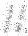
- FIGS. 1 to 3 distinguish the locking system according to the invention the fact that in each case a different number of electronics housings with the help of the locking system to an electronics housing system can be merged.
- the locking system shown in Fig. 1 consists of only two pieces of housing, namely an initial piece 1 and an end piece 2, so that with this locking system also only two electronics housed together can be.
- the locking system also includes another key element 3.
- the key element 3 can be in the as Key holder trained initial piece 1 and inserted by a Rotation can be locked in the end piece 2 designed as a lock.
- the key element 3 has a cylinder head 4 with a slot 5 Turning the key element 3 on.
- a cylinder head 4 By training one End of the key element 3 as a cylinder head 4 and the arrangement of a Slot 5 in the cylinder head 4, the key element 3 as a very small Component are produced, for example the cylinder head 4 only Have thread size M 3.
- the slot 5 in the Cylinder head 4 is the key element 3 even with such small dimensions still easy to operate, for example using the tip of a Screwdriver.
- the key element 3 with his Cylinder head 4 is completely retractable in the starting piece 1.
- a blind bore 6 is formed, which is also used for support of the cylinder head 4 of the key element 3 is used.
- the other end of the Key element 3 is designed as a key bit 7, so that the key element 3 by a simple rotation in the end piece, for example 90 ° 2 can be locked.
- FIG. 1a to 1d are the individual locking steps of the invention Locking system easily recognizable.
- Fig. 1a the start piece 1, the end piece 2 and the key element 3 completely separated from each other, d. H. a first electronics housing in which the Starting piece 1 is arranged, and a second electronics housing in which the end piece 2 is arranged are not yet connected.
- the first locking step is - as shown in Fig. 1b - that Key element 3 inserted into the starting piece 1.
- the key bit 7 of the key element 3 in a vertical position. is the key element 3 fully inserted into the starting piece 1, so the cylinder head 4 of the key element 3 is supported in the interior of the starting piece 1 from the blind hole 6 and is completely in the beginning 1 sunk.
- a third step the starting piece 1 and the tail 2, d. H. the first electronics housing and the second electronics housing, pushed together so that the key bit 7 of the key element 3 engages in the end piece 2 designed as a lock.
- the Start 1 and end 2 are now already put together (Fig. 1c), but they are not yet locked together, so that the the two electronics housings are not yet locked together.
- the last locking step is the key bit 7 of the key element rotated by about 90 °, whereby the key bit 7 in the end piece 2 is arranged that the key element 3 is not in this position can be pulled out more.
- the fact that the cylinder head 4 of the Key element 3 rests in the blind hole 6 of the starting piece 1 now the beginning piece 1 is locked with the end piece 2.
- the locking system according to the invention shown in Fig. 2 differs from the previously described locking system according to FIG. 1, that it consists of three housing pieces, namely an initial piece 1, one End piece 2 and an intermediate piece 8 is also present.
- the in Fig. 2nd locking system shown can thus three electronics housing an electronic housing system.
- the intermediate piece 8 is now designed such that it consists of an end piece 9 and an initial piece 10, wherein in the initial piece 10 the cylinder head 4 of a first key element 3 is retractable and in the end piece 9 the key bit 7 of a second key element 3 can be locked.
- the end piece 9 of the intermediate piece 8 is formed in exactly the same way as that separate end piece 2.
- the start piece 10 of the intermediate piece 8 formed according to the separate starting piece 1 and also has like the starting piece 1, a blind bore 6 for receiving the cylinder head 4 of a key element 3.
- FIGS. 1 and 2 shows that the initial piece 1 either directly or by interposing the intermediate piece 8 can be connected to the end piece 2.
- FIGS. 1a to 1d show various locking steps.
- the intermediate piece 8 is locked with the end piece 2, for which a first key element 3 through the end piece 9 in the start piece 10 is pushed until the cylinder head 4 of the key element 3 rests in the blind hole 6 in the starting piece 10 (Fig. 2b).
- the intermediate piece 8 and the end piece 2 are pushed together (Fig. 2c) and then the intermediate piece 8 locked with the end piece 2, by the key bit 7 of the first key element 3 by approximately 90 ° is rotated (Fig. 2d).
- FIG. 3 shows a locking system as a further exemplary embodiment for locking a total of six electronics housings, one electronics housing each have a start piece 1 and an end piece 2, and in four Electronics housing an intermediate piece 8 is formed.
- the lock of such an electronics housing system takes place again step by step, so that first the end piece 2 with the first intermediate piece 8 (shown on the far left in FIG. 3) 8 is locked.
- the starting piece 9 of the first intermediate piece 8 inserted a first key element 3 and after plugging together of the end piece 2 with the first intermediate piece 8 of the key bit 7 the key element 3 locked by a 90 ° rotation in the end piece 2.
- the fourth intermediate piece 8 is shown in dashed lines to indicate that the locking system can be supplemented by further intermediate pieces can.
- the locking system according to the invention is therefore a Cascadable locking of any number of electronics housings into one Electronic housing system possible, the number of interlocked Electronics housing can be increased or decreased at any time. So can with the locking system so n electronics housing mechanically be firmly connected to each other, which is why the locking system is a starting piece 1, an end piece 2, (n-2) intermediate pieces 8 and (n-1) key elements 3 has.
- the locking system according to the invention is particularly simple also by making both the individual intermediate pieces 8 as well as the individual key elements 3, regardless of the number the electronics housing to be locked are identical.
- each electronics housing is constructed identically, namely each has at least one intermediate piece 8. With such an electronics housing system would then be the starting piece 10 of the first intermediate piece 8 and the end piece 9 of the last intermediate piece 8 are not used become. A separate start piece 1 and a separate end piece 2 are then not necessary.
Landscapes
- Engineering & Computer Science (AREA)
- Microelectronics & Electronic Packaging (AREA)
- Lock And Its Accessories (AREA)
- Casings For Electric Apparatus (AREA)
- Mounting Components In General For Electric Apparatus (AREA)
Abstract
Description
- Fig. 1
- ein Ausführungsbeispiel des erfindungsgemäßen Verriegelungssystems eines Elektronikgehäusesystems mit nur zwei Gehäusestücken, dargestellt in vier Verriegelungsschritten,
- Fig. 2
- eine Darstellung eines Verriegelungssystems gemäß Fig. 1 mit drei Gehäusestücken,
- Fig. 3
- ein Ausführungsbeispiel des erfindungsgemäßen Verriegelungssystems eines Elektronikgehäusesystems mit sechs Gehäusestücken, dargestellt in zwei Verriegelungszuständen, und
- Fig. 4
- ein Ausführungsbeispiel des erfindungsgemäßen Verriegelungssystems eines Elektronikgehäusesystems gemäß Fig. 3, vollständig verriegelt, in Seitenansicht und im Schnitt.
Claims (10)
- Elektronikgehäusesystem mit mindestens zwei, insbesondere scheibenförmigen, auf eine Tragschiene aufrastbaren Elektronikgehäusen, mit einem Verriegelungssystem, bestehend aus mindestens zwei Gehäusestücken, nämlich einem Anfangsstück (1) und einem Endstück (2), und einem Schlüsselelement (3), wobei das Anfangsstück (1) als Schlüsselaufnahme und das Endstück (2) als Schloß ausgebildet ist und die beiden Gehäusestücke durch eine Drehung des Schlüsselelements (3) in dem Endstück (2) miteinander verriegelbar sind.
- Elektronikgehäusesystem nach Anspruch 1, dadurch gekennzeichnet, daß das Schlüsselelement (3) einen Zylinderkopf (4) mit mindestens einem Schlitz (5) zur Drehbetätigung aufweist.
- Elektronikgehäusesystem nach Anspruch 2, dadurch gekennzeichnet, daß der Zylinderkopf (4) des Schlüsselelements (3) im Anfangsstück versenkbar ist.
- Elektronikgehäusesystem nach Anspruch 2 oder 3, dadurch gekennzeichnet, daß im Anfangsstück (1) eine Sackbohrung (6) zur Abstützung des Zylinderkopfs (4) des Schlüsselelements (3) ausgebildet ist.
- Elektronikgehäusesystem nach einem der Ansprüche 1 bis 4, dadurch gekennzeichnet, daß das Ende des Schlüsselelements (3) als Schlüsselbart (7) ausgebildet ist.
- Elektronikgehäusesystem nach einem der Ansprüche 1 bis 5, dadurch gekennzeichnet, daß zwischen dem Anfangsstück (1) und dem Endstück (3) mindestens ein Zwischenstück (8) angeordnet ist.
- Elektronikgehäusesystem nach Anspruch 6, dadurch gekennzeichnet, daß das Zwischenstück (8) ein Endstück (9) und ein Anfangsstück (10) aufweist und in dem Endstück (9) das Ende eines ersten Schlüsselelements (3) verriegelbar ist und in dem Anfangsstück (10) der Zylinderkopf (4) eines zweiten Schlüsselelements (3) versenkbar ist.
- Elektronikgehäusesystem nach Anspruch 6 oder 7 mit n Elektronikgehäusen, dadurch gekennzeichnet, daß das Verriegelungssystem aus einem Anfangsstück (1), einem Endstück (2), (n - 2) Zwischenstücken (8) sowie (n - 1) Schlüsselelementen (3) besteht.
- Elektronikgehäusesystem nach einem der Ansprüche 6 bis 8, dadurch gekennzeichnet, daß ein Anfangsstück (1), ein Endstück (2) oder ein Zwischenstück (8) in einer Ecke des Elektronikgehäuse angeordnet ist, daß insbesondere das Anfangsstück (1), das Endstück (2) und das Zwischenstück (8) jeweils einteilig mit dem Elektronikgehäuse ausgebildet sind.
- Elektronikgehäusesystem nach einem der Ansprüche 6 bis 8, dadurch gekennzeichnet, daß mehrere Anfangsstücke (1) oder mehrere Endstücke (2) oder mehrere Zwischenstücke (8) jeweils Teil des Elektronikgehäuses sind, insbesondere in mindestens zwei Ecken der Elektronikgehäuse je ein Anfangsstück (1) oder ein Endstück (2) oder ein Zwischenstück (8) angeordnet sind.
Applications Claiming Priority (3)
| Application Number | Priority Date | Filing Date | Title |
|---|---|---|---|
| DE10049218 | 2000-09-28 | ||
| DE10049218A DE10049218C2 (de) | 2000-09-28 | 2000-09-28 | Elektronikgehäusesystem |
| CA002363618A CA2363618C (en) | 2000-09-28 | 2001-11-22 | Electronic housing system |
Publications (3)
| Publication Number | Publication Date |
|---|---|
| EP1194026A2 true EP1194026A2 (de) | 2002-04-03 |
| EP1194026A3 EP1194026A3 (de) | 2003-12-10 |
| EP1194026B1 EP1194026B1 (de) | 2006-03-22 |
Family
ID=32070506
Family Applications (1)
| Application Number | Title | Priority Date | Filing Date |
|---|---|---|---|
| EP01122092A Expired - Lifetime EP1194026B1 (de) | 2000-09-28 | 2001-09-14 | Elektronikgehäusesystem |
Country Status (4)
| Country | Link |
|---|---|
| US (1) | US6679646B2 (de) |
| EP (1) | EP1194026B1 (de) |
| CA (1) | CA2363618C (de) |
| DE (1) | DE10049218C2 (de) |
Families Citing this family (29)
| Publication number | Priority date | Publication date | Assignee | Title |
|---|---|---|---|---|
| US6764351B2 (en) * | 2001-08-27 | 2004-07-20 | Campagnie Deutsch GmbH | Electrical connector |
| FR2853367B1 (fr) * | 2003-04-03 | 2005-06-24 | Lisi Automotive Rapid | Dispositif de fixation, notamment de maintien d'un empilement d'au moins deux panneaux |
| US6881003B1 (en) * | 2003-06-18 | 2005-04-19 | Acuity Brands, Inc. | Latching mechanism for high mast lighting system |
| US6955515B2 (en) * | 2003-12-09 | 2005-10-18 | International Business Machines Corporation | Locking turn pin |
| US7345235B2 (en) * | 2004-03-17 | 2008-03-18 | Yamaha Corporation | Keyboard musical instrument having keys equipped with balancers biting into keys and method for securing balancers to keys |
| US7865326B2 (en) | 2004-04-20 | 2011-01-04 | National Instruments Corporation | Compact input measurement module |
| JP2006259675A (ja) * | 2005-02-18 | 2006-09-28 | Ricoh Printing Systems Ltd | 印刷装置 |
| TWI286736B (en) * | 2005-03-15 | 2007-09-11 | Yamaha Corp | Movable part firmly equipped with balance weight, musical instrument and method of assembling balance weight therein |
| US20060237515A1 (en) * | 2005-04-22 | 2006-10-26 | Fci Americas Technology, Inc. | Exothermic weld mold clamp |
| US20080160875A1 (en) * | 2005-08-15 | 2008-07-03 | Boaz Leicht | Interconnectible Building Elements For Intellectual Challenge Games |
| JP4419949B2 (ja) * | 2005-12-13 | 2010-02-24 | ソニー株式会社 | 表示板の取り付け構造 |
| CN101688410A (zh) | 2006-10-23 | 2010-03-31 | 艾可品牌美国有限公司 | 安全设备 |
| US8540545B2 (en) * | 2010-02-06 | 2013-09-24 | Boaz Leicht | Interconnectible building elements for intellectual challenge games |
| US7861472B2 (en) * | 2008-05-01 | 2011-01-04 | Guy Carl Thompson | Mounting apparatus for protective covers |
| CN101752527B (zh) * | 2008-12-05 | 2012-10-17 | 鸿富锦精密工业(深圳)有限公司 | 固定机构及采用该固定机构的电子装置 |
| JP5794675B2 (ja) * | 2011-06-01 | 2015-10-14 | キヤノン株式会社 | 表示板の取付け構造並びに雲台装置及びカメラ装置 |
| WO2012095050A2 (zh) * | 2012-02-28 | 2012-07-19 | 华为技术有限公司 | 机柜骨架及具有该机柜骨架的机柜 |
| TW201349984A (zh) * | 2012-05-31 | 2013-12-01 | Hon Hai Prec Ind Co Ltd | 機櫃式伺服器及其組合 |
| DE202012102014U1 (de) * | 2012-06-01 | 2013-09-03 | Weidmüller Interface GmbH & Co. KG | Anschlussvorrichtungsanordnung, insbesondere für eine Tragschiene |
| CN103455094B (zh) * | 2012-06-04 | 2016-08-17 | 联想(北京)有限公司 | 一种电子设备以及一种扩展坞 |
| US9098252B2 (en) * | 2012-06-21 | 2015-08-04 | Hewlett-Packard Development Company, L.P. | Peripheral component interconnect riser cage fastener |
| US10779646B2 (en) * | 2013-07-25 | 2020-09-22 | Qubicaamf Worldwide, Llc | Furniture system and arrangement thereof |
| DE102014001500B4 (de) | 2014-02-06 | 2019-08-14 | Abb Ag | Anordnung aus einem Basisgerät und einem Anbaugerät |
| CN106595209B (zh) * | 2016-12-21 | 2019-03-29 | 合肥华凌股份有限公司 | 锁扣、保温板组件和冰箱 |
| WO2019040309A1 (en) * | 2017-08-21 | 2019-02-28 | Hubbell Incorporated | HANDLE FOR EXOTHERMIC MOLD WITH SPRING CONNECTORS |
| US10738999B2 (en) | 2017-10-03 | 2020-08-11 | Hubbell Incorporated | Trigger devices for exothermix welds |
| US10837207B2 (en) * | 2017-11-28 | 2020-11-17 | Rockwell Automation Technologies, Inc. | Control center door latch |
| US20240337444A1 (en) * | 2021-05-27 | 2024-10-10 | Refractory Intellectual Property Gmbh & Co. Kg | Holding device for holding a ceramic anchor brick to a furnace wall, a furnace comprising such a holding device, and a method for fastening such a holding device to a furnace wall |
| CN219812295U (zh) * | 2023-05-05 | 2023-10-10 | 捷普电子(新加坡)公司 | 锁定机构及电子装置 |
Family Cites Families (8)
| Publication number | Priority date | Publication date | Assignee | Title |
|---|---|---|---|---|
| DE1871657U (de) * | 1962-09-28 | 1963-05-09 | Siemens Ag | Baugruppenanordnung. |
| US3995923A (en) * | 1975-03-20 | 1976-12-07 | Shell Irving W | Panel locking arrangement |
| IT1146519B (it) * | 1981-07-17 | 1986-11-12 | Finike Italiana Marposs | Apparecchiatura elettrica di tipo modulare |
| US4551110A (en) * | 1984-05-24 | 1985-11-05 | Cpg Products Corp. | Rotatable cam for use in a toy construction set |
| DE3907412A1 (de) * | 1989-03-08 | 1990-09-13 | Ant Nachrichtentech | Gehaeusesystem zur aufnahme von elektrischen einschueben |
| US5275029A (en) * | 1992-07-13 | 1994-01-04 | Fort Lock Corporation | Refrigerator door lock |
| NO303746B1 (no) * | 1995-07-27 | 1998-08-24 | Kongsberg Offshore As | Anordning til befestigelse av to innretninger |
| US5788347A (en) * | 1996-03-08 | 1998-08-04 | Rabinovitz; Josef | Interlocking system for computer peripheral enclosures and the like |
-
2000
- 2000-09-28 DE DE10049218A patent/DE10049218C2/de not_active Expired - Fee Related
-
2001
- 2001-09-14 EP EP01122092A patent/EP1194026B1/de not_active Expired - Lifetime
- 2001-11-22 CA CA002363618A patent/CA2363618C/en not_active Expired - Fee Related
- 2001-11-28 US US09/994,920 patent/US6679646B2/en not_active Expired - Fee Related
Also Published As
| Publication number | Publication date |
|---|---|
| CA2363618C (en) | 2008-11-18 |
| CA2363618A1 (en) | 2003-05-22 |
| US6679646B2 (en) | 2004-01-20 |
| DE10049218A1 (de) | 2002-05-08 |
| DE10049218C2 (de) | 2003-01-02 |
| US20020114665A1 (en) | 2002-08-22 |
| EP1194026A3 (de) | 2003-12-10 |
| EP1194026B1 (de) | 2006-03-22 |
Similar Documents
| Publication | Publication Date | Title |
|---|---|---|
| EP1194026B1 (de) | Elektronikgehäusesystem | |
| EP1811604B1 (de) | Elektrischer Reihenklemmenblock | |
| DE102019106082B4 (de) | Schaltschranksystem mit dichtungseinsatz | |
| EP2839544B1 (de) | Prüfklemmenblock | |
| DE9217174U1 (de) | Gehäuse für ein Gerät | |
| EP0019141B1 (de) | Nockenschalter | |
| DE102016119061B4 (de) | Rangierwabe mit gebildeter Haltenut für Markierungsschilder und Wabenbaustein | |
| EP2203947B1 (de) | Akkupack und elektrogerät mit dreidimensionalen kodiermitteln | |
| DE10004752A1 (de) | Instrumentengruppe und Sicherungsblock | |
| EP3440745B1 (de) | Wabenbaustein zur ausbildung einer rangierwabe, rangierwabe und werkzeug zum lösen eines wabenbausteins aus einer rangierwabe | |
| DE3943752C2 (de) | Pneumatische oder hydraulische Ventileinheit | |
| DE69923506T2 (de) | Elektrisches Verbindungsgehäuse | |
| DE102024125089A1 (de) | Steckereinsatz | |
| EP2562879B1 (de) | Querrangierung unterstützendes E/A-Modul und elektrisches Kontaktelement | |
| DE102015110223B4 (de) | Baugruppe einer Klemmeneinrichtung zum Anschließen von elektrischen Leitern | |
| EP2734693B1 (de) | Einsteckschloss mit einer platine | |
| DE102017104029A1 (de) | Anschlusselement | |
| DE3743557C2 (de) | Befestigungssystem für Gerätesockel | |
| EP1220372A2 (de) | Steckverbinder-Gehäuse mit Kodiereinrichtung | |
| EP4270675B1 (de) | Festpoliger kontakteinsatz und kontakteinsatzanordnung | |
| DE19902811C1 (de) | Kodiervorrichtung und Kodierverfahren zur Kodierung eines elektrischen Gerätes | |
| DE102009059011A1 (de) | Verbindungssystem zum Verbinden eines einreihigen Gehäuses mit einem Anschlusselement | |
| EP0576822A1 (de) | Modular Schaltelementblock | |
| DE10249123B4 (de) | Elektrotechnische Vorrichtung zum Einsatz in Installationsdosen | |
| DE102023132109A1 (de) | Sensor-Aktor-Verteiler |
Legal Events
| Date | Code | Title | Description |
|---|---|---|---|
| PUAI | Public reference made under article 153(3) epc to a published international application that has entered the european phase |
Free format text: ORIGINAL CODE: 0009012 |
|
| AK | Designated contracting states |
Kind code of ref document: A2 Designated state(s): AT BE CH CY DE DK ES FI FR GB GR IE IT LI LU MC NL PT SE TR |
|
| AX | Request for extension of the european patent |
Free format text: AL;LT;LV;MK;RO;SI |
|
| PUAL | Search report despatched |
Free format text: ORIGINAL CODE: 0009013 |
|
| AK | Designated contracting states |
Kind code of ref document: A3 Designated state(s): AT BE CH CY DE DK ES FI FR GB GR IE IT LI LU MC NL PT SE TR |
|
| AX | Request for extension of the european patent |
Extension state: AL LT LV MK RO SI |
|
| 17P | Request for examination filed |
Effective date: 20031205 |
|
| 17Q | First examination report despatched |
Effective date: 20040217 |
|
| AKX | Designation fees paid |
Designated state(s): AT DE FR IT |
|
| GRAP | Despatch of communication of intention to grant a patent |
Free format text: ORIGINAL CODE: EPIDOSNIGR1 |
|
| GRAS | Grant fee paid |
Free format text: ORIGINAL CODE: EPIDOSNIGR3 |
|
| GRAA | (expected) grant |
Free format text: ORIGINAL CODE: 0009210 |
|
| AK | Designated contracting states |
Kind code of ref document: B1 Designated state(s): AT DE FR IT |
|
| REF | Corresponds to: |
Ref document number: 50109268 Country of ref document: DE Date of ref document: 20060511 Kind code of ref document: P |
|
| ET | Fr: translation filed | ||
| PLBE | No opposition filed within time limit |
Free format text: ORIGINAL CODE: 0009261 |
|
| STAA | Information on the status of an ep patent application or granted ep patent |
Free format text: STATUS: NO OPPOSITION FILED WITHIN TIME LIMIT |
|
| 26N | No opposition filed |
Effective date: 20061227 |
|
| PGFP | Annual fee paid to national office [announced via postgrant information from national office to epo] |
Ref country code: AT Payment date: 20130923 Year of fee payment: 13 Ref country code: DE Payment date: 20130819 Year of fee payment: 13 |
|
| PGFP | Annual fee paid to national office [announced via postgrant information from national office to epo] |
Ref country code: IT Payment date: 20130921 Year of fee payment: 13 |
|
| PGFP | Annual fee paid to national office [announced via postgrant information from national office to epo] |
Ref country code: FR Payment date: 20130920 Year of fee payment: 13 |
|
| REG | Reference to a national code |
Ref country code: DE Ref legal event code: R119 Ref document number: 50109268 Country of ref document: DE |
|
| REG | Reference to a national code |
Ref country code: AT Ref legal event code: MM01 Ref document number: 321439 Country of ref document: AT Kind code of ref document: T Effective date: 20140914 |
|
| REG | Reference to a national code |
Ref country code: FR Ref legal event code: ST Effective date: 20150529 |
|
| PG25 | Lapsed in a contracting state [announced via postgrant information from national office to epo] |
Ref country code: DE Free format text: LAPSE BECAUSE OF NON-PAYMENT OF DUE FEES Effective date: 20150401 |
|
| PG25 | Lapsed in a contracting state [announced via postgrant information from national office to epo] |
Ref country code: AT Free format text: LAPSE BECAUSE OF NON-PAYMENT OF DUE FEES Effective date: 20140914 Ref country code: FR Free format text: LAPSE BECAUSE OF NON-PAYMENT OF DUE FEES Effective date: 20140930 Ref country code: IT Free format text: LAPSE BECAUSE OF NON-PAYMENT OF DUE FEES Effective date: 20140914 |