EP1193431A2 - Soupape, en particulier soupape de radiateur - Google Patents
Soupape, en particulier soupape de radiateur Download PDFInfo
- Publication number
- EP1193431A2 EP1193431A2 EP01203478A EP01203478A EP1193431A2 EP 1193431 A2 EP1193431 A2 EP 1193431A2 EP 01203478 A EP01203478 A EP 01203478A EP 01203478 A EP01203478 A EP 01203478A EP 1193431 A2 EP1193431 A2 EP 1193431A2
- Authority
- EP
- European Patent Office
- Prior art keywords
- valve
- housing
- valve element
- valve seat
- counter
- Prior art date
- Legal status (The legal status is an assumption and is not a legal conclusion. Google has not performed a legal analysis and makes no representation as to the accuracy of the status listed.)
- Granted
Links
Images


Classifications
-
- F—MECHANICAL ENGINEERING; LIGHTING; HEATING; WEAPONS; BLASTING
- F16—ENGINEERING ELEMENTS AND UNITS; GENERAL MEASURES FOR PRODUCING AND MAINTAINING EFFECTIVE FUNCTIONING OF MACHINES OR INSTALLATIONS; THERMAL INSULATION IN GENERAL
- F16K—VALVES; TAPS; COCKS; ACTUATING-FLOATS; DEVICES FOR VENTING OR AERATING
- F16K11/00—Multiple-way valves, e.g. mixing valves; Pipe fittings incorporating such valves
- F16K11/02—Multiple-way valves, e.g. mixing valves; Pipe fittings incorporating such valves with all movable sealing faces moving as one unit
- F16K11/08—Multiple-way valves, e.g. mixing valves; Pipe fittings incorporating such valves with all movable sealing faces moving as one unit comprising only taps or cocks
- F16K11/085—Multiple-way valves, e.g. mixing valves; Pipe fittings incorporating such valves with all movable sealing faces moving as one unit comprising only taps or cocks with cylindrical plug
-
- F—MECHANICAL ENGINEERING; LIGHTING; HEATING; WEAPONS; BLASTING
- F16—ENGINEERING ELEMENTS AND UNITS; GENERAL MEASURES FOR PRODUCING AND MAINTAINING EFFECTIVE FUNCTIONING OF MACHINES OR INSTALLATIONS; THERMAL INSULATION IN GENERAL
- F16K—VALVES; TAPS; COCKS; ACTUATING-FLOATS; DEVICES FOR VENTING OR AERATING
- F16K1/00—Lift valves or globe valves, i.e. cut-off apparatus with closure members having at least a component of their opening and closing motion perpendicular to the closing faces
- F16K1/32—Details
- F16K1/52—Means for additional adjustment of the rate of flow
Definitions
- the invention relates to a valve, in particular a radiator valve, with a housing that has an inlet port and has an outlet port, wherein in Flow path between these two ports one Shut-off device with a valve element and one Valve seat device is arranged.
- Such a valve designed as a radiator valve is known from WO 99/22282.
- valve it looks different if the valve is connected incorrectly will, i.e. the feed line of a heating system is connected to the outlet port. In this case the water flows over the valve element to the valve seat and from there into the inlet connection. If the valve closes, the valve element is closed towards the valve seat emotional. If the gap between the valve element and the valve seat falls below a certain size, the valve element closes abruptly, which also sudden increase in pressure at the outlet connection Has. This increase in pressure manifests itself in a water hammer, which not only results in unpleasant noises has, but also cause damage to the pipe system can. This water hammer can also be caused by trigger an external pulse, for example through another valve that suddenly closes or opens, a pump that starts or stops, or other. These causes, which have not yet been fully clarified are particularly critical when the valve is incorrectly installed.
- the invention has for its object a valve to be able to operate independently of the flow direction.
- valve seat device has two valve seat exits, one of which one to the inlet connection and the other to the outlet connection is assigned, the valve element and the valve seat device is adjustable relative to one another are, so that the valve element optionally with cooperates with one or with the other valve seat outlet.
- valve element in one Valve element housing is arranged and the valve seat device has a counter housing, at least one of these two parts valve element housing and counter housing is rotatably arranged in the housing.
- By twisting one of these two parts can either the valve element opposite the inflowing Liquid or the inflowing liquid opposite position the valve element.
- Rotatable parts are relative easy to seal against each other.
- the rotatable part opposite sealed the housing with a peripheral seal is.
- the peripheral seal also provides a rotational movement the tightness reliably safe.
- the rotatable part is preferably over a Snap ring assembly held in the housing.
- the snap ring arrangement secures the rotatable part against one axial movement, but allows a rotary movement.
- the rotatable part is preferably in its two possible functional positions locked to the housing. This allows a fitter to easily recognize when the correct turning position is reached. With a locking arrangement, this position can then be secured. If necessary, the valve element can be position relatively exactly opposite the valve seat.
- the counter housing as a tube with two in the axial direction and lateral angularly offset Is formed, depending on the Rotational position of the pipe in either of the sockets Cover with one valve seat opening or the other Spigot covered with an outflow opening in the housing comes, with the other nozzle from the housing is closed.
- the desired flow paths in the radiator valve relative easy to implement without the need for the To move the valve seat itself. If the one nozzle is in overlap with the valve seat opening the heating fluid flow through the pipe and that Flow the valve element through the valve seat. The backflow takes place via the outflow opening and outside around the pipe.
- the counter housing preferably has an externally accessible one Torque application area. About the torque application area you can turn on the necessary torque Exercise the counter housing to twist it in the housing. For example, the torque application area act about a hexagon socket.
- the radiator valve can also be adjusted if it is already installed.
- the torque application surface is covered by a removable cap. That cap can be screwed onto the housing from the outside. she offers protection of the torque application area from pollution and can also do so be used, the radiator valve to the outside seal.
- valve element arranged eccentrically in the valve element housing is, the valve seat device two valve seats having. By turning the valve element housing you can choose the valve element with one or the other valve seat to cover bring.
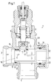
- Fig. 1 shows a radiator valve 1 with a housing 2, which has an inlet port 3 and an outlet port 4 has.
- Arrows 5 indicate a flow path for one Heating liquid, for example hot water the radiator valve.
- the valve element 6 has that cooperates with a valve seat 7.
- the Valve element 6 can only be shown schematically Way from a valve lifter 8 to the valve seat 7 or be moved away from it.
- a spring 9 is provided which the valve element 6 without the occurrence of external Forces forces away from valve seat 7.
- the flow direction shown in Fig. 1 is the "normal" flow at which the valve element 6 is flowed through through the valve seat 7. In order to arise neither when opening nor when closing any Problems. If the valve element 6 on the Valve seat 7 is moved, then there is a gradual Throttling the water flow in that a Gap between the valve element 6 and the valve seat 7 is continuously made smaller, the drive of the valve element 6 exclusively via the valve tappet 8 takes place.
- the radiator valve points 1 a hereinafter referred to as the counter housing 10 Part that is arranged in the housing 2.
- the counter housing which is shown in perspective in Fig. 3, is arranged in a bore 11, which is an extension of the inlet port 3 forms.
- the counter housing 10 is a tube 12 with a first flange 13 and a second flange 14 formed, the two Flanges 13, 14 are sealed in the housing 2. 0-rings 15, 16 are used for sealing.
- the counter housing 10 also has two connecting pieces 17, 18 on, which abut the inner wall of the bore 11 and are also sealed there.
- the two sockets 17, 18 are arranged axially offset from one another on the tube 12 and communicate with the interior 19 of the tube.
- the counter housing 10 is rotatably mounted in the housing 2 and there with Secured with the help of a snap ring 20 against axial displacement.
- a torque application surface 21 is provided, for example a hexagon socket. With the help of this Torque application surface 21, which is accessible from the outside the counter housing 10 can now be in the housing 2 be twisted.
- the torque application area can still be covered by a cap 22 which, if necessary with the interposition of a not shown Seal on which the housing is screwed.
- valve element 6 is always through the valve seat 7 is flown through.
- the heating liquid passes from the inlet port 3 through the interior 19 of the tube 12 and the nozzle 17 to the valve seat 7 and the valve element 6 flows through the valve seat 7 through.
- the through the gap between the valve element 6 and valve seat 7 liquid can then pass through an outflow opening 23 (FIG. 2), which is next to the valve seat is arranged, re-enter the bore 11, there flow around the tube 12 outside and finally get into the drain port 4.
- arrows 5 are with double dashes executed.
- Fig. 2 now shows a situation in which the flow direction is reversed through the housing 2, i.e. the heating fluid enters the outlet port 4 and at the inlet port 3.
- the valve element 6 also flow through the valve seat can, the counter housing 10 in the bore 11 by 90 Degrees rotated.
- the nozzle 17 comes out of engagement with the valve seat 7 and is from the inside of the Hole 11 covered.
- the nozzle 18 comes in Cover with the outlet opening 23.
- the heating fluid flows around the tube 12 and passes through the valve seat 7 to the valve element 6. From there the heating fluid through the discharge opening 23 and the nozzle 18 in the interior 19 of the tube 12 and passed there to inlet port 3.
- the flow direction of the heating fluid in the radiator valve 1 can be turned by rotating the counter housing change in a simple way. at this configuration, only one valve seat 7 is required, which is independent of the flow direction of the Heating fluid cooperates with the valve element 6.
- the counter housing 10 thus forms two valve seat outputs, namely once the nozzle 17, which is in alignment can be brought to the valve seat 7 and the other a space 29 between the outside of the tube 12 and the inside of the bore 11 is arranged.
- Fig. 4 shows a modified embodiment in which same parts are provided with the same reference numerals.
- the radiator valve 1 now has a housing 25 two valve seats 7a, 7b.
- the valve element 6 is arranged in a valve element housing 26, the opposite the housing 25 is rotatable about an axis 27.
- the valve element 6 is eccentric to this axis 27 arranged, just like the valve seats 7a, 7b. If So the valve element housing 26 by 180 degrees Twisted axis 27, then the valve element 6 comes out Engagement with the valve seat 7a and in engagement with the Valve seat 7b.
- the valve element 6 In the position shown in Fig. 4 of the valve element housing 26 is the valve element 6 for a flow direction from the inlet port 3 to Outlet port 4 positioned. In this case The valve element 6 flows through the valve seat 7a.
- valve element housing not shown 26 in which the valve element 6 with the Valve seat 7b interacts
- the heating fluid can flow from the outlet port to the inlet port 3.
- the valve element 6 is passed through flowed through the valve seat 7b.
- valve element housing 26 is over the snap ring 20 held in the housing 25 and sealed by an 0-ring 15.
- Locking elements may be provided, for example in the form of spring-loaded Balls that are in corresponding recesses the peripheral surface of the counter housing 10 or the valve element housing 26 snap into place. Additionally or alternatively, there can also be a mark on the outside be provided, the "correct" position of each parts to be rotated.
Landscapes
- Engineering & Computer Science (AREA)
- General Engineering & Computer Science (AREA)
- Mechanical Engineering (AREA)
- Taps Or Cocks (AREA)
- Details Of Valves (AREA)
- Multiple-Way Valves (AREA)
- Lift Valve (AREA)
- Quick-Acting Or Multi-Walled Pipe Joints (AREA)
- Preventing Unauthorised Actuation Of Valves (AREA)
- Chair Legs, Seat Parts, And Backrests (AREA)
Applications Claiming Priority (2)
| Application Number | Priority Date | Filing Date | Title |
|---|---|---|---|
| DE10048688 | 2000-09-30 | ||
| DE10048688A DE10048688C2 (de) | 2000-09-30 | 2000-09-30 | Ventil, insbesondere Heizkörperventil |
Publications (3)
| Publication Number | Publication Date |
|---|---|
| EP1193431A2 true EP1193431A2 (fr) | 2002-04-03 |
| EP1193431A3 EP1193431A3 (fr) | 2003-03-12 |
| EP1193431B1 EP1193431B1 (fr) | 2005-06-08 |
Family
ID=7658356
Family Applications (1)
| Application Number | Title | Priority Date | Filing Date |
|---|---|---|---|
| EP01203478A Expired - Lifetime EP1193431B1 (fr) | 2000-09-30 | 2001-09-13 | Soupape, en particulier soupape de radiateur |
Country Status (9)
| Country | Link |
|---|---|
| EP (1) | EP1193431B1 (fr) |
| CN (1) | CN1203269C (fr) |
| AT (1) | ATE297519T1 (fr) |
| BG (1) | BG105916A (fr) |
| CZ (1) | CZ20013396A3 (fr) |
| DE (1) | DE10048688C2 (fr) |
| PL (1) | PL197275B1 (fr) |
| RU (1) | RU2206005C1 (fr) |
| UA (1) | UA67830C2 (fr) |
Cited By (1)
| Publication number | Priority date | Publication date | Assignee | Title |
|---|---|---|---|---|
| EP3193049A1 (fr) * | 2016-01-15 | 2017-07-19 | Danfoss A/S | Vanne |
Families Citing this family (5)
| Publication number | Priority date | Publication date | Assignee | Title |
|---|---|---|---|---|
| DE102004041213B4 (de) * | 2004-08-26 | 2006-06-01 | Danfoss A/S | Ventil |
| EP2988071B1 (fr) * | 2014-08-19 | 2016-06-22 | IMI Hydronic Engineering International SA | Régulateur de débit |
| CN105485357A (zh) * | 2016-01-22 | 2016-04-13 | 黄德修 | 一种截止式套膜防结垢阀芯及其阀门 |
| CN108253162A (zh) * | 2016-12-29 | 2018-07-06 | 比亚迪股份有限公司 | 膨胀开关阀 |
| CN108561359B (zh) * | 2018-04-25 | 2020-07-24 | 台州市路桥欧铂喷塑电泳有限公司 | 流量阀 |
Citations (1)
| Publication number | Priority date | Publication date | Assignee | Title |
|---|---|---|---|---|
| WO1999022282A1 (fr) | 1997-10-23 | 1999-05-06 | Myson Heating Controls Limited | Valves de regulation de debit |
Family Cites Families (6)
| Publication number | Priority date | Publication date | Assignee | Title |
|---|---|---|---|---|
| DE24398C (de) * | G. SEIDEMAN in London | Neuerungen an Hähnen und Niederschraubventilen | ||
| DE1139707B (de) * | 1960-02-17 | 1962-11-15 | Regulation Automatique S A R L | Absperrhahn, insbesondere fuer Warmwasser- oder Dampfheizungsanlagen |
| US3265351A (en) * | 1963-12-20 | 1966-08-09 | Crane Co | Segmental disc stem connection for valves |
| DE9113745U1 (fr) * | 1991-11-05 | 1992-01-16 | Haller, Alfred | |
| DE9421996U1 (de) * | 1993-05-10 | 1997-07-10 | Kermi Gmbh | Anschlußvorrichtung zum Anschluß eines Heizkörpers und Patrone zum Einbau in diese |
| DE19740157A1 (de) * | 1997-09-12 | 1999-03-18 | Elster Produktion Gmbh | Gasdruckregelgerät |
-
2000
- 2000-09-30 DE DE10048688A patent/DE10048688C2/de not_active Expired - Fee Related
-
2001
- 2001-09-11 UA UA2001096269A patent/UA67830C2/uk unknown
- 2001-09-13 EP EP01203478A patent/EP1193431B1/fr not_active Expired - Lifetime
- 2001-09-13 AT AT01203478T patent/ATE297519T1/de not_active IP Right Cessation
- 2001-09-19 BG BG05916A patent/BG105916A/xx unknown
- 2001-09-21 CZ CZ20013396A patent/CZ20013396A3/cs unknown
- 2001-09-26 RU RU2001126974/06A patent/RU2206005C1/ru not_active IP Right Cessation
- 2001-09-26 PL PL349864A patent/PL197275B1/pl unknown
- 2001-09-29 CN CNB011410515A patent/CN1203269C/zh not_active Expired - Fee Related
Patent Citations (1)
| Publication number | Priority date | Publication date | Assignee | Title |
|---|---|---|---|---|
| WO1999022282A1 (fr) | 1997-10-23 | 1999-05-06 | Myson Heating Controls Limited | Valves de regulation de debit |
Cited By (1)
| Publication number | Priority date | Publication date | Assignee | Title |
|---|---|---|---|---|
| EP3193049A1 (fr) * | 2016-01-15 | 2017-07-19 | Danfoss A/S | Vanne |
Also Published As
| Publication number | Publication date |
|---|---|
| UA67830C2 (uk) | 2004-07-15 |
| ATE297519T1 (de) | 2005-06-15 |
| CZ20013396A3 (cs) | 2002-05-15 |
| DE10048688C2 (de) | 2003-01-30 |
| EP1193431B1 (fr) | 2005-06-08 |
| CN1344873A (zh) | 2002-04-17 |
| BG105916A (en) | 2002-09-30 |
| PL197275B1 (pl) | 2008-03-31 |
| RU2206005C1 (ru) | 2003-06-10 |
| EP1193431A3 (fr) | 2003-03-12 |
| CN1203269C (zh) | 2005-05-25 |
| DE10048688A1 (de) | 2002-04-25 |
| PL349864A1 (en) | 2002-04-08 |
Similar Documents
| Publication | Publication Date | Title |
|---|---|---|
| DE3126507C2 (fr) | ||
| EP2271969B1 (fr) | Système de robinetterie permettant de réguler le débit ou la différence de pression | |
| EP0122323A1 (fr) | Soupape à double siège avec deux têtes de soupape | |
| EP1193432B1 (fr) | Soupape, en particulier soupape de radiateur | |
| EP3037699B1 (fr) | Vanne mélangeuse | |
| EP1193431B1 (fr) | Soupape, en particulier soupape de radiateur | |
| DE10324874B3 (de) | Ventil, insbesondere Dampfventil | |
| EP1213519B1 (fr) | Soupape de radiateur | |
| DE102007013505A1 (de) | Armaturenkombination zur Regelung der Durchflussmenge oder des Differenzdruckes | |
| EP0905454B1 (fr) | Armature de connexion pour connecter un vase d'expansion à une tuyauterie | |
| DE4312067B4 (de) | Ventil | |
| DE19636410B4 (de) | Armatur für Wasserleitungen | |
| DE2907565C2 (de) | Kombinierte Selbstschluß- und Mischarmatur | |
| DE3107929A1 (de) | "anschlussnippel fuer ein ventil, insbesondere heizkoerperventil" | |
| EP3690325B1 (fr) | Dispositif de remplissage pour appareils de chauffage combinés | |
| EP2644789B1 (fr) | Ensemble modulaire d'un agencement de séparation de tuyaux | |
| EP0527313B1 (fr) | Robinetterie pour conduits d'eau | |
| DE10007072B4 (de) | Mehrwegeventil und System mit einem derartigen Mehrwegeventil | |
| EP2149729A1 (fr) | Vanne à boisseau sphérique dotée d'une connexion en T | |
| DE10055614B4 (de) | Ventil,insbesondere Heizkörprventil | |
| DE4423856C2 (de) | Mischventil mit einem Zusatzgerät | |
| EP1207327B1 (fr) | Soupape, en particulier soupape de radiateur | |
| DE102005018585A1 (de) | Adapter für Klimageräte | |
| DE2216801C3 (de) | Mischventil zum Mischen von Heiß- und Kaltwasser | |
| DE4345539B4 (de) | Kartuschenbaugruppe für ein Mischventil für Flüssigkeiten |
Legal Events
| Date | Code | Title | Description |
|---|---|---|---|
| PUAI | Public reference made under article 153(3) epc to a published international application that has entered the european phase |
Free format text: ORIGINAL CODE: 0009012 |
|
| AK | Designated contracting states |
Kind code of ref document: A2 Designated state(s): AT BE CH CY DE DK ES FI FR GB GR IE IT LI LU MC NL PT SE TR |
|
| AX | Request for extension of the european patent |
Free format text: AL;LT;LV;MK;RO;SI |
|
| PUAL | Search report despatched |
Free format text: ORIGINAL CODE: 0009013 |
|
| AK | Designated contracting states |
Kind code of ref document: A3 Designated state(s): AT BE CH CY DE DK ES FI FR GB GR IE IT LI LU MC NL PT SE TR |
|
| AX | Request for extension of the european patent |
Extension state: AL LT LV MK RO SI |
|
| 17P | Request for examination filed |
Effective date: 20030404 |
|
| AKX | Designation fees paid |
Designated state(s): AT BE CH CY DE DK ES FI FR GB GR IE IT LI LU MC NL PT SE TR |
|
| GRAP | Despatch of communication of intention to grant a patent |
Free format text: ORIGINAL CODE: EPIDOSNIGR1 |
|
| GRAS | Grant fee paid |
Free format text: ORIGINAL CODE: EPIDOSNIGR3 |
|
| GRAA | (expected) grant |
Free format text: ORIGINAL CODE: 0009210 |
|
| RBV | Designated contracting states (corrected) |
Designated state(s): AT BE CH CY DK ES FI FR GB GR IE IT LI LU MC NL PT SE TR |
|
| AK | Designated contracting states |
Kind code of ref document: B1 Designated state(s): AT BE CH CY DK ES FI FR GB GR IE IT LI LU MC NL PT SE TR |
|
| PG25 | Lapsed in a contracting state [announced via postgrant information from national office to epo] |
Ref country code: NL Free format text: LAPSE BECAUSE OF FAILURE TO SUBMIT A TRANSLATION OF THE DESCRIPTION OR TO PAY THE FEE WITHIN THE PRESCRIBED TIME-LIMIT Effective date: 20050608 Ref country code: TR Free format text: LAPSE BECAUSE OF FAILURE TO SUBMIT A TRANSLATION OF THE DESCRIPTION OR TO PAY THE FEE WITHIN THE PRESCRIBED TIME-LIMIT Effective date: 20050608 Ref country code: IE Free format text: LAPSE BECAUSE OF FAILURE TO SUBMIT A TRANSLATION OF THE DESCRIPTION OR TO PAY THE FEE WITHIN THE PRESCRIBED TIME-LIMIT Effective date: 20050608 Ref country code: FI Free format text: LAPSE BECAUSE OF FAILURE TO SUBMIT A TRANSLATION OF THE DESCRIPTION OR TO PAY THE FEE WITHIN THE PRESCRIBED TIME-LIMIT Effective date: 20050608 Ref country code: IT Free format text: LAPSE BECAUSE OF FAILURE TO SUBMIT A TRANSLATION OF THE DESCRIPTION OR TO PAY THE FEE WITHIN THE PRESCRIBED TIME-LIMIT;WARNING: LAPSES OF ITALIAN PATENTS WITH EFFECTIVE DATE BEFORE 2007 MAY HAVE OCCURRED AT ANY TIME BEFORE 2007. THE CORRECT EFFECTIVE DATE MAY BE DIFFERENT FROM THE ONE RECORDED. Effective date: 20050608 |
|
| REG | Reference to a national code |
Ref country code: GB Ref legal event code: FG4D Free format text: NOT ENGLISH |
|
| REG | Reference to a national code |
Ref country code: CH Ref legal event code: EP |
|
| REG | Reference to a national code |
Ref country code: DE Ref legal event code: 8566 |
|
| REG | Reference to a national code |
Ref country code: IE Ref legal event code: FG4D Free format text: LANGUAGE OF EP DOCUMENT: GERMAN |
|
| PG25 | Lapsed in a contracting state [announced via postgrant information from national office to epo] |
Ref country code: DK Free format text: LAPSE BECAUSE OF FAILURE TO SUBMIT A TRANSLATION OF THE DESCRIPTION OR TO PAY THE FEE WITHIN THE PRESCRIBED TIME-LIMIT Effective date: 20050908 Ref country code: GR Free format text: LAPSE BECAUSE OF FAILURE TO SUBMIT A TRANSLATION OF THE DESCRIPTION OR TO PAY THE FEE WITHIN THE PRESCRIBED TIME-LIMIT Effective date: 20050908 Ref country code: SE Free format text: LAPSE BECAUSE OF FAILURE TO SUBMIT A TRANSLATION OF THE DESCRIPTION OR TO PAY THE FEE WITHIN THE PRESCRIBED TIME-LIMIT Effective date: 20050908 |
|
| PG25 | Lapsed in a contracting state [announced via postgrant information from national office to epo] |
Ref country code: AT Free format text: LAPSE BECAUSE OF NON-PAYMENT OF DUE FEES Effective date: 20050913 Ref country code: CY Free format text: LAPSE BECAUSE OF FAILURE TO SUBMIT A TRANSLATION OF THE DESCRIPTION OR TO PAY THE FEE WITHIN THE PRESCRIBED TIME-LIMIT Effective date: 20050913 |
|
| PG25 | Lapsed in a contracting state [announced via postgrant information from national office to epo] |
Ref country code: ES Free format text: LAPSE BECAUSE OF FAILURE TO SUBMIT A TRANSLATION OF THE DESCRIPTION OR TO PAY THE FEE WITHIN THE PRESCRIBED TIME-LIMIT Effective date: 20050919 |
|
| GBT | Gb: translation of ep patent filed (gb section 77(6)(a)/1977) |
Effective date: 20050902 |
|
| PG25 | Lapsed in a contracting state [announced via postgrant information from national office to epo] |
Ref country code: LU Free format text: LAPSE BECAUSE OF NON-PAYMENT OF DUE FEES Effective date: 20050930 Ref country code: LI Free format text: LAPSE BECAUSE OF NON-PAYMENT OF DUE FEES Effective date: 20050930 Ref country code: CH Free format text: LAPSE BECAUSE OF NON-PAYMENT OF DUE FEES Effective date: 20050930 Ref country code: MC Free format text: LAPSE BECAUSE OF NON-PAYMENT OF DUE FEES Effective date: 20050930 Ref country code: BE Free format text: LAPSE BECAUSE OF NON-PAYMENT OF DUE FEES Effective date: 20050930 |
|
| PG25 | Lapsed in a contracting state [announced via postgrant information from national office to epo] |
Ref country code: PT Free format text: LAPSE BECAUSE OF FAILURE TO SUBMIT A TRANSLATION OF THE DESCRIPTION OR TO PAY THE FEE WITHIN THE PRESCRIBED TIME-LIMIT Effective date: 20051114 |
|
| NLV1 | Nl: lapsed or annulled due to failure to fulfill the requirements of art. 29p and 29m of the patents act | ||
| REG | Reference to a national code |
Ref country code: IE Ref legal event code: FD4D |
|
| ET | Fr: translation filed | ||
| PLBE | No opposition filed within time limit |
Free format text: ORIGINAL CODE: 0009261 |
|
| STAA | Information on the status of an ep patent application or granted ep patent |
Free format text: STATUS: NO OPPOSITION FILED WITHIN TIME LIMIT |
|
| REG | Reference to a national code |
Ref country code: CH Ref legal event code: PL |
|
| 26N | No opposition filed |
Effective date: 20060309 |
|
| BERE | Be: lapsed |
Owner name: DANFOSS A/S Effective date: 20050930 |
|
| REG | Reference to a national code |
Ref country code: FR Ref legal event code: PLFP Year of fee payment: 15 |
|
| REG | Reference to a national code |
Ref country code: FR Ref legal event code: PLFP Year of fee payment: 16 |
|
| REG | Reference to a national code |
Ref country code: FR Ref legal event code: PLFP Year of fee payment: 17 |
|
| PGFP | Annual fee paid to national office [announced via postgrant information from national office to epo] |
Ref country code: FR Payment date: 20170824 Year of fee payment: 17 |
|
| PGFP | Annual fee paid to national office [announced via postgrant information from national office to epo] |
Ref country code: GB Payment date: 20180912 Year of fee payment: 18 |
|
| PG25 | Lapsed in a contracting state [announced via postgrant information from national office to epo] |
Ref country code: FR Free format text: LAPSE BECAUSE OF NON-PAYMENT OF DUE FEES Effective date: 20180930 |
|
| GBPC | Gb: european patent ceased through non-payment of renewal fee |
Effective date: 20190913 |
|
| PG25 | Lapsed in a contracting state [announced via postgrant information from national office to epo] |
Ref country code: GB Free format text: LAPSE BECAUSE OF NON-PAYMENT OF DUE FEES Effective date: 20190913 |