EP1193409B1 - Verriegelungsanordnung für sphärische Lager und Verrieglungsverfahren davon - Google Patents
Verriegelungsanordnung für sphärische Lager und Verrieglungsverfahren davon Download PDFInfo
- Publication number
- EP1193409B1 EP1193409B1 EP01117444A EP01117444A EP1193409B1 EP 1193409 B1 EP1193409 B1 EP 1193409B1 EP 01117444 A EP01117444 A EP 01117444A EP 01117444 A EP01117444 A EP 01117444A EP 1193409 B1 EP1193409 B1 EP 1193409B1
- Authority
- EP
- European Patent Office
- Prior art keywords
- outer race
- housing
- spherical bearing
- flange
- bearing
- Prior art date
- Legal status (The legal status is an assumption and is not a legal conclusion. Google has not performed a legal analysis and makes no representation as to the accuracy of the status listed.)
- Expired - Lifetime
Links
- 238000000034 method Methods 0.000 title claims description 13
- 230000002093 peripheral effect Effects 0.000 description 9
- 230000000452 restraining effect Effects 0.000 description 8
- 230000013011 mating Effects 0.000 description 3
- 230000000694 effects Effects 0.000 description 1
Images


Classifications
-
- F—MECHANICAL ENGINEERING; LIGHTING; HEATING; WEAPONS; BLASTING
- F16—ENGINEERING ELEMENTS AND UNITS; GENERAL MEASURES FOR PRODUCING AND MAINTAINING EFFECTIVE FUNCTIONING OF MACHINES OR INSTALLATIONS; THERMAL INSULATION IN GENERAL
- F16C—SHAFTS; FLEXIBLE SHAFTS; ELEMENTS OR CRANKSHAFT MECHANISMS; ROTARY BODIES OTHER THAN GEARING ELEMENTS; BEARINGS
- F16C11/00—Pivots; Pivotal connections
- F16C11/04—Pivotal connections
- F16C11/06—Ball-joints; Other joints having more than one degree of angular freedom, i.e. universal joints
- F16C11/0614—Ball-joints; Other joints having more than one degree of angular freedom, i.e. universal joints the female part of the joint being open on two sides
Definitions
- the invention relates to a spherical bearing and more particularly, to a spherical bearing for restraining an outer race from turning relative to a housing.
- FIG. 6 shows an example of a lock structure of a spherical bearing 11.
- the spherical bearing 11 is locked to a housing 14 through staking (also referred to as V-staking) for locking an outer race 12 to the housing 14 by staking a V-shaped groove 13 as an annular staking groove formed in each side of the outer race 12 using a dedicated tool (not shown).
- V-staking also referred to as V-staking
- a large rotating torque is exerted to the bearing.
- the outer race 12 may turn relative to the housing 14, which may cause the risk of wearing an outer peripheral surface 12a of the outer race 12. It is, thus, necessary to restrain the turn of the outer race 12 relative to the housing 14.
- a flange 26 is formed on the edge of one side of an outer race 25 and an extending portion 26a is formed by extending a part of the lateral edge of the flange 26 in a radial direction of the outer race 25.
- a screw portion 24 is formed on the outer peripheral surface of the other side of the outer race 25. Then the outer race 25 is inserted into a bearing hole 23 to bring the flange 26 into abutment against a housing 22, a lock nut 28 is screwed to be locked to the screw portion 24 of the outer race 25 through a lock washer 27, and a pin 29 is driven into the housing 22 to penetrate through the extending portion 26a of the flange 26. As a result, the spherical bearing 21 is locked to the housing 22 while restraining the outer race 25 from turning relative to the housing 22.
- the above-identified lock structure for the spherical bearing 21 has been conventionally employed.
- the lock structure of the spherical bearing 21 described above requires additional parts for locking the spherical bearing 21 to the housing 22, that is, the lock washer 27, the lock nut 28 and the pin 29, resulting in complicated component control as well as in deteriorated efficiency of assembly. Moreover, the flange 26 of the outer race 25 has to be extended to drive the pin 29, causing increase in the material cost owing to increased size (weight) thereof.
- a spherical bearing having a simple structure, which is capable of restraining an outer race from turning relative to a housing to simplify the assembly and to reduce the cost, and the lock method thereof.
- the spherical bearing having a spherical surface of an inner race slidably supported on an inner spherical surface of the outer race which is fitted into a bearing hole of the housing so as to be locked thereto includes a protruding portion formed on a periphery of one side of the bearing hole, a flange formed on one side of the outer race, an engagement portion formed in the flange and brought into engagement with the protruding portion, and an annular staking groove formed in the other side of the outer race.
- the spherical bearing is fitted into the bearing hole to bring the engagement portion formed in the flange of the outer race into engagement with the protruding portion on the periphery of one side of the bearing hole. Meanwhile the staking groove in the other side of the outer race is staked to lock the spherical bearing to the housing.
- the spherical bearing is fitted into the bearing hole to bring the engagement portion formed in the flange of the outer race into engagement with the protruding portion on the periphery of one side of the bearing hole. Meanwhile the staking groove in the other side of the outer race is staked to lock the spherical bearing to the housing by restraining the spherical bearing from turning relative to the housing.
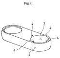
- a lock structure of a spherical bearing 1 is provided with a plurality of protruding portions 4 (in this embodiment, four protruding portions) formed on a periphery of one side of a bearing hole 3 of a housing 2 at equal spacing, a flange 6 formed on one side of an outer race 5, and notches 7 formed in the flange 6 as engagement portions to mate with the respective protruding portions 4 as shown in Fig. 5.
- protruding portions 4 in this embodiment, four protruding portions
- an outer peripheral surface 5b of the outer race 5 is inserted into the bearing hole 3 of the housing 2 to bring the notches 7 of the flange 6 into engagement with the respective protruding portions 4 of the housing 2.
- a V-shaped groove 9 as an annular staking groove formed in the other side of the outer race 5 is then staked such that the spherical bearing 1 is locked to the housing 2.
- the spherical bearing 1 according to this embodiment of the invention is structured in which a spherical surface 8a of an inner race 8 is rotatably and slidably supported on an inner spherical surface 5a of the outer race 5.
- An eccentric shaft hole 8b is formed in the inner race 8 so as to allow a shaft member (not shown) to be inserted therethrough.
- the flange 6 with a predetermined width is provided on the end of one side of the outer race 5.
- the notches 7 each having a predetermined width (the reference numeral 'h' in Fig. 2) are provided in the flange 6 by notching in the radial direction of the outer race 5.
- the V-shaped groove 9 is formed as the annular staking groove in the other side of the outer race 5. Being staked with a dedicated tool (not shown), the V-shaped groove 9 deforms its outer portion so as to mate with the shape of a chamfered portion 5c formed on the end of the other side of the bearing hole 3.
- the bearing hole 3 fitted with the outer peripheral face 5b of the outer race 5 with a predetermined fitting tolerance is formed in the housing 2.
- a plurality of protruding portions 4 are formed on the periphery of one side of the bearing hole 3 so as to be brought into engagement with the respective notches (engagement portions) 7 of the outer race 5.
- the outer peripheral face 5b of the outer race 5 is fitted into the bearing hole 3 of the housing 2 and the notches 7 formed in the flange 6 of the outer race 5 are engaged with the respective protruding portions 4 of the housing 2.
- the protruding portions 4 serve to restrain the outer race 5 from turning relative to the housing 2.
- four protruding portions 4 are provided at equal spacing on the periphery of one side of the bearing hole 3 of the housing 2 of the lock structure of the spherical bearing 1.
- the number of the protruding portions 4 and the arrangement thereof are, however, not limited thereto. They may be determined based on a required rotating torque of the spherical bearing 1 and the like.
- the spherical bearing 1 has the eccentric shaft hole 8b of the inner race 8. However, it is not limited thereto.
- the spherical bearing 1 is mounted onto the housing 2 by fitting the outer peripheral face 5b of the outer race 5 of the spherical bearing 1 into the bearing hole 3 of the housing 2 so as to bring the notches 7 as the engagement portions formed in the flange 6 of the outer race 5 into engagement with the respective protruding portions 4 formed on the periphery of one side of the bearing hole 3. Concurrently the flange 6 is brought into abutment against the housing 2. Then as shown in Fig.
- the V-shaped groove (staking groove) 9 formed in the other side of the outer race 5 is staked with a dedicated tool (not shown) such that the V-shaped groove 9 deforms its outer portion to mate with the shape of the chamfered portion 5c formed on the end of the other side of the bearing hole 3.
- This structure allows the spherical bearing 1 to the housing 2 by restraining the spherical bearing 1 from turning relative to the housing 2.
- the protruding portions 4 formed on the periphery of one side of the bearing hole 3 of the housing 2, the flange 6 formed on one side of the outer race 5, and the notches 7 (engagement portions) formed in the flange 6 mating with the protruding portions 4, respectively.
- the outer peripheral face 5b of the outer race 5 of the spherical bearing 1 is fitted into the bearing hole 3 of the housing 2 to bring the notches 7 of the flange 6 into engagement with the respective protruding portions 4. Meanwhile the V-shaped groove 9 as the annular staking groove formed in the other side of the outer race 5 is staked.
- the spherical bearing 1 can be locked to the housing 2 with a simple structure yet reliably restraining the spherical bearing 1 from turning relative to the housing 2.
- the respective design of the shape of the flange 6 of the outer race 5 and the shape of the protruding portions 4 of the housing 2 can be made to a substantially high degree of freedom. This makes it possible to easily satisfy requirements for strength or efficiency of process.
- the present invention requires no components for locking a spherical bearing 21 to a housing 22, for example, a lock washer 27, a lock nut 28, a pin 29 and the like. This makes it possible to realize simplified component control as well as improving efficiency of assembly. Moreover, as the flange 6 of the outer race 5 does not have to be extended in a radial direction for driving the pin 29 thereinto, the size (weight) of material can be reduced, thus greatly reducing the cost.
- the lock structure of the spherical bearing 1 is provided with the protruding portions formed on a periphery of one side of a bearing hole of a housing, a flange formed on one side of an outer race, and notches (engagement portions) formed in the flange mating with the respective protruding portions.
- An outer peripheral surface of the outer race of the spherical bearing is fitted into the bearing hole of the housing to bring the notches of the flange into engagement with the respective protruding portions of the housing.
- annular V-shaped groove (staking groove) formed in the other side of the outer race is then staked such that the spherical bearing is locked to the housing with a simplified structure while restraining the spherical bearing from turning relative to the housing.
- the respective design of the shape of the flange of the outer race and the shape of the protruding portions of the housing can be made to a substantially high degree of freedom. This makes it possible to easily satisfy requirements for strength or efficiency of process.
- the present invention requires no components for locking the spherical bearing to the housing, for example, a lock washer, a lock nut, a pin and the like.
- the lock structure of the spherical bearing is provided with the protruding portions formed on a periphery of one side of the bearing hole of the housing, the flange formed on one side of the outer race, and the notches (engagement portions) formed in the flange mating with the respective protruding portions.
- the outer peripheral surface of the outer race of the spherical bearing is fitted into the bearing hole of the housing to bring the notches of the flange into engagement with the respective protruding portions of the housing.
- the annular V-shaped groove (staking groove) formed in the other side of the outer race is then staked such that the spherical bearing is locked to the housing.
- the respective design of the shape of the flange of the outer race and the shape of the protruding portions of the housing can be made to a substantially high degree of freedom. This makes it possible to easily satisfy requirements for strength or efficiency of process.
- the present invention requires no components for locking the spherical bearing to the housing, for example, the lock washer, the lock nut, the pin and the like. This makes it possible to realize simplified component control as well as improving efficiency of assembly.
- the flange of the outer race does not have to be extended in a radial direction for driving the pin thereinto, the size (weight) of material can be reduced, thus greatly reducing the cost.
Landscapes
- Engineering & Computer Science (AREA)
- General Engineering & Computer Science (AREA)
- Mechanical Engineering (AREA)
- Support Of The Bearing (AREA)
- Pivots And Pivotal Connections (AREA)
- Mounting Of Bearings Or Others (AREA)
- Sliding-Contact Bearings (AREA)
- Rolling Contact Bearings (AREA)
Claims (2)
- Ein Sphärolager (1), welches eine sphärische Oberfläche (8a) eines inneren Laufrings (8) aufweist, der gleitend in einer inneren sphärischen Oberfläche (5b) eines äusseren Laufrings (5) gelagert ist, welcher derart in ein Lagerloch (3) eines Gehäuses (2) eingebaut ist, dass er mit diesem verriegelt ist, umfassend:einen an einem Rand einer Seite von besagtem Lagerloch (3) geformten, vorstehenden Teil (4);einen an einer Seite von besagtem, äusseren Laufring (5) geformten Flansch (6);ein in besagten Flansch (6) geformter und mit besagtem vorstehenden Teil (4) in Eingriff gebrachter Eingriffsteil (7); undeine in die andere Seite des besagten äusseren Laufrings (5) eingeformte, ringförmige Verkörnungsnut (9).
- Ein Verfahren zur Verriegelung eines Sphärolagers (1), welches eine sphärische Oberfläche (8a) eines inneren Laufrings (8) aufweist, der gleitend in einer inneren sphärischen Oberfläche (5b) eines äusseren Laufrings (5) gelagert ist, welcher derart in ein Lagerloch (3) eines Gehäuses (2) eingebaut ist, dass er mit diesem verriegelt ist, wobei ein vorstehendes Teil (4) an einem Rand einer Seite von besagtem Lagerloch (3) geformt wird; ein Flansch (6) an einer Seite von besagtem, äusseren Laufring (5) geformt wird; ein Eingriffsteil (7) in besagten Flansch (6) geformt wird, um mit besagtem, vorstehenden Teil (4) in Eingriff gebracht zu werden; und eine ringförmige Verkörnungsnut (9) in die andere Seite des besagten, äusseren Laufrings (5) geformt wird, das verfahren die folgenden Schritte beinhaltet:besagtes Eingriffsteil (7) wird in Eingriff mit besagtem, vorstehenden Teil (4) gebracht und besagte ringförmige Verkörnungsnut (9) wird derart verkörnt, dass ein Drehen des besagten Sphärolagers (1) relativ zu besagtem Gehäuse (2) unterdrückt wird.
Applications Claiming Priority (2)
| Application Number | Priority Date | Filing Date | Title |
|---|---|---|---|
| JP2000292421 | 2000-09-26 | ||
| JP2000292421A JP2002106556A (ja) | 2000-09-26 | 2000-09-26 | 球面滑り軸受の固定構造及びその固定方法 |
Publications (2)
| Publication Number | Publication Date |
|---|---|
| EP1193409A1 EP1193409A1 (de) | 2002-04-03 |
| EP1193409B1 true EP1193409B1 (de) | 2005-06-08 |
Family
ID=18775364
Family Applications (1)
| Application Number | Title | Priority Date | Filing Date |
|---|---|---|---|
| EP01117444A Expired - Lifetime EP1193409B1 (de) | 2000-09-26 | 2001-07-19 | Verriegelungsanordnung für sphärische Lager und Verrieglungsverfahren davon |
Country Status (4)
| Country | Link |
|---|---|
| US (1) | US6612744B2 (de) |
| EP (1) | EP1193409B1 (de) |
| JP (1) | JP2002106556A (de) |
| DE (1) | DE60111322T2 (de) |
Families Citing this family (15)
| Publication number | Priority date | Publication date | Assignee | Title |
|---|---|---|---|---|
| FR2851804B1 (fr) * | 2003-02-27 | 2005-05-13 | Hutchinson | Bielle anti-vibratoire et son procede de fabrication |
| US6959942B2 (en) * | 2003-10-21 | 2005-11-01 | Cnh America Llc | Ball hitch for an implement drawbar of an agricultural vehicle |
| FR2865512B1 (fr) * | 2004-01-23 | 2007-05-11 | Airbus France | Dispositif de jonction articulee |
| ATE556239T1 (de) * | 2006-01-31 | 2012-05-15 | John Horvat | Kriechschutz-vorrichtung |
| US20070223849A1 (en) * | 2006-03-21 | 2007-09-27 | Roller Bearing Company Of America, Inc. | Spherical plain bearing and a housing in combination with a spherical plain bearing |
| US9157471B2 (en) | 2011-09-26 | 2015-10-13 | Kenneth Alvin Jungeberg | Friction locking spherical joint |
| US9093053B2 (en) | 2011-11-03 | 2015-07-28 | Kenneth Alvin Jungeberg | Arrestor for user operated devices |
| US10012261B2 (en) | 2011-09-26 | 2018-07-03 | Kenneth Alvin Jungeberg | Method and apparatus for releasably immobilizing an attachment to an external object |
| US20130233997A1 (en) * | 2012-03-12 | 2013-09-12 | United Technologies Corporation | Turbine engine case mount |
| US9366296B2 (en) * | 2014-01-13 | 2016-06-14 | The Boeing Company | Swaging features that lock retaining elements for bearings |
| US10077801B2 (en) * | 2014-06-16 | 2018-09-18 | Joshua Manning Marable | Connecting system for connecting a tensioning member to a free-space shaft |
| US9458889B2 (en) | 2015-02-20 | 2016-10-04 | Lockheed Martin Corporation | Reverse bearing system, apparatus, and method |
| CN110608228A (zh) * | 2019-09-04 | 2019-12-24 | 东南大学 | 带v型槽的杆端关节轴承及其制造方法 |
| CN113685436A (zh) * | 2021-08-23 | 2021-11-23 | 航天精工股份有限公司 | 一种高度单元化的航天航空用关节轴承 |
| EP4174333B1 (de) | 2021-10-27 | 2024-07-17 | Microtecnica S.r.l. | Lageranordnung |
Family Cites Families (6)
| Publication number | Priority date | Publication date | Assignee | Title |
|---|---|---|---|---|
| US3465405A (en) | 1966-10-11 | 1969-09-09 | Donald L Sullivan | Method of fabricating ball bushing |
| US3662462A (en) | 1970-02-09 | 1972-05-16 | Rohr Corp | Method of securing a bearing race within a bore in a housing |
| CA1245699A (en) * | 1984-12-03 | 1988-11-29 | Howard M. Martinie | Means for securing a bearing to a shaft |
| US4614444A (en) * | 1985-07-05 | 1986-09-30 | Cadillac Rubber & Plastics, Inc. | Bearing seal assembly |
| DE4213298A1 (de) | 1992-04-23 | 1993-10-28 | Scharwaechter Gmbh Co Kg | Haltestangenlagerung für Kraftwagentürfeststeller |
| FR2768782B1 (fr) | 1997-09-19 | 1999-11-12 | Sarma | Procede d'assemblage d'une rotule d'articulation et rotule d'articulation obtenue par un tel procede |
-
2000
- 2000-09-26 JP JP2000292421A patent/JP2002106556A/ja active Pending
-
2001
- 2001-07-11 US US09/902,097 patent/US6612744B2/en not_active Expired - Fee Related
- 2001-07-19 EP EP01117444A patent/EP1193409B1/de not_active Expired - Lifetime
- 2001-07-19 DE DE60111322T patent/DE60111322T2/de not_active Expired - Fee Related
Also Published As
| Publication number | Publication date |
|---|---|
| US20020037117A1 (en) | 2002-03-28 |
| JP2002106556A (ja) | 2002-04-10 |
| US6612744B2 (en) | 2003-09-02 |
| DE60111322T2 (de) | 2006-03-23 |
| EP1193409A1 (de) | 2002-04-03 |
| DE60111322D1 (de) | 2005-07-14 |
Similar Documents
| Publication | Publication Date | Title |
|---|---|---|
| EP1193409B1 (de) | Verriegelungsanordnung für sphärische Lager und Verrieglungsverfahren davon | |
| EP1133018B1 (de) | Entkopplungswiderstehende Anordnung für einen elektrischen Verbinder | |
| US20050025604A1 (en) | Combination lock washer and spindle bearing assembly | |
| CA2978106C (en) | Rotary electric rotor and method of manufacturing rotary electric rotor | |
| EP1375966B1 (de) | Kugelgewindespindel und Herstellungsverfahren dafür | |
| GB2265197A (en) | Self locking nut | |
| US5797696A (en) | Snap connection system | |
| DE10059666A1 (de) | Kraftübertragungsvorrichtung | |
| US5417512A (en) | End connector with captive ball and bearing half with crushed elements | |
| JP2001336606A (ja) | ディファレンシャル装置 | |
| JPH10324108A (ja) | ベアリングロックナット・ワッシャ構造 | |
| KR100363490B1 (ko) | 등속조인트의외륜과축의접합구조 | |
| US6056581A (en) | Latch detent/stop mechanism for electrical connectors | |
| JPH05272546A (ja) | 回転伝達部材の回転軸取付け構造 | |
| US6811345B2 (en) | Fastener assembly with self centering antirotation elements | |
| EP1084350B1 (de) | Flache sicherungsscheibe | |
| JPS63303261A (ja) | トルク伝達用アセンブリー | |
| US12203530B2 (en) | Offset planetary gear fastener assembly and planetary gear system | |
| KR200285475Y1 (ko) | 벨트 풀리 | |
| US5087146A (en) | Assembly for the positioning of two structural elements in relation to each other | |
| WO1989005920A1 (en) | Locking arrangement for locking a nut | |
| JP7403170B2 (ja) | 緩み止めナットとその締付方法 | |
| US6086479A (en) | Alignment device | |
| JPH05306720A (ja) | 回転伝達部材の回転軸取付け構造 | |
| KR20020038343A (ko) | 회전체 체결기구 |
Legal Events
| Date | Code | Title | Description |
|---|---|---|---|
| PUAI | Public reference made under article 153(3) epc to a published international application that has entered the european phase |
Free format text: ORIGINAL CODE: 0009012 |
|
| AK | Designated contracting states |
Kind code of ref document: A1 Designated state(s): AT BE CH CY DE DK ES FI FR GB GR IE IT LI LU MC NL PT SE TR Kind code of ref document: A1 Designated state(s): DE FR GB |
|
| AX | Request for extension of the european patent |
Free format text: AL;LT;LV;MK;RO;SI |
|
| 17P | Request for examination filed |
Effective date: 20021002 |
|
| AKX | Designation fees paid |
Free format text: DE FR GB |
|
| GRAP | Despatch of communication of intention to grant a patent |
Free format text: ORIGINAL CODE: EPIDOSNIGR1 |
|
| GRAS | Grant fee paid |
Free format text: ORIGINAL CODE: EPIDOSNIGR3 |
|
| GRAA | (expected) grant |
Free format text: ORIGINAL CODE: 0009210 |
|
| AK | Designated contracting states |
Kind code of ref document: B1 Designated state(s): DE FR GB |
|
| REG | Reference to a national code |
Ref country code: GB Ref legal event code: FG4D |
|
| REF | Corresponds to: |
Ref document number: 60111322 Country of ref document: DE Date of ref document: 20050714 Kind code of ref document: P |
|
| ET | Fr: translation filed | ||
| PLBE | No opposition filed within time limit |
Free format text: ORIGINAL CODE: 0009261 |
|
| STAA | Information on the status of an ep patent application or granted ep patent |
Free format text: STATUS: NO OPPOSITION FILED WITHIN TIME LIMIT |
|
| 26N | No opposition filed |
Effective date: 20060309 |
|
| PGFP | Annual fee paid to national office [announced via postgrant information from national office to epo] |
Ref country code: DE Payment date: 20060713 Year of fee payment: 6 |
|
| PGFP | Annual fee paid to national office [announced via postgrant information from national office to epo] |
Ref country code: FR Payment date: 20060719 Year of fee payment: 6 Ref country code: GB Payment date: 20060719 Year of fee payment: 6 |
|
| GBPC | Gb: european patent ceased through non-payment of renewal fee |
Effective date: 20070719 |
|
| PG25 | Lapsed in a contracting state [announced via postgrant information from national office to epo] |
Ref country code: DE Free format text: LAPSE BECAUSE OF NON-PAYMENT OF DUE FEES Effective date: 20080201 |
|
| PG25 | Lapsed in a contracting state [announced via postgrant information from national office to epo] |
Ref country code: GB Free format text: LAPSE BECAUSE OF NON-PAYMENT OF DUE FEES Effective date: 20070719 |
|
| REG | Reference to a national code |
Ref country code: FR Ref legal event code: ST Effective date: 20080331 |
|
| PG25 | Lapsed in a contracting state [announced via postgrant information from national office to epo] |
Ref country code: FR Free format text: LAPSE BECAUSE OF NON-PAYMENT OF DUE FEES Effective date: 20070731 |