EP1084350B1 - Flache sicherungsscheibe - Google Patents
Flache sicherungsscheibe Download PDFInfo
- Publication number
- EP1084350B1 EP1084350B1 EP99922012A EP99922012A EP1084350B1 EP 1084350 B1 EP1084350 B1 EP 1084350B1 EP 99922012 A EP99922012 A EP 99922012A EP 99922012 A EP99922012 A EP 99922012A EP 1084350 B1 EP1084350 B1 EP 1084350B1
- Authority
- EP
- European Patent Office
- Prior art keywords
- circumferential edge
- flat
- key washer
- sections
- concentric
- Prior art date
- Legal status (The legal status is an assumption and is not a legal conclusion. Google has not performed a legal analysis and makes no representation as to the accuracy of the status listed.)
- Expired - Lifetime
Links
- 230000013011 mating Effects 0.000 claims description 18
- 239000002184 metal Substances 0.000 claims description 9
- 230000008878 coupling Effects 0.000 claims description 6
- 238000010168 coupling process Methods 0.000 claims description 6
- 238000005859 coupling reaction Methods 0.000 claims description 6
- 230000015572 biosynthetic process Effects 0.000 claims description 5
- 238000010276 construction Methods 0.000 description 1
- 238000003780 insertion Methods 0.000 description 1
- 230000037431 insertion Effects 0.000 description 1
- 238000003754 machining Methods 0.000 description 1
- 230000014759 maintenance of location Effects 0.000 description 1
- 238000004519 manufacturing process Methods 0.000 description 1
- 230000004048 modification Effects 0.000 description 1
- 238000012986 modification Methods 0.000 description 1
- 230000002093 peripheral effect Effects 0.000 description 1
Images


Classifications
-
- F—MECHANICAL ENGINEERING; LIGHTING; HEATING; WEAPONS; BLASTING
- F16—ENGINEERING ELEMENTS AND UNITS; GENERAL MEASURES FOR PRODUCING AND MAINTAINING EFFECTIVE FUNCTIONING OF MACHINES OR INSTALLATIONS; THERMAL INSULATION IN GENERAL
- F16B—DEVICES FOR FASTENING OR SECURING CONSTRUCTIONAL ELEMENTS OR MACHINE PARTS TOGETHER, e.g. NAILS, BOLTS, CIRCLIPS, CLAMPS, CLIPS OR WEDGES; JOINTS OR JOINTING
- F16B3/00—Key-type connections; Keys
-
- F—MECHANICAL ENGINEERING; LIGHTING; HEATING; WEAPONS; BLASTING
- F16—ENGINEERING ELEMENTS AND UNITS; GENERAL MEASURES FOR PRODUCING AND MAINTAINING EFFECTIVE FUNCTIONING OF MACHINES OR INSTALLATIONS; THERMAL INSULATION IN GENERAL
- F16D—COUPLINGS FOR TRANSMITTING ROTATION; CLUTCHES; BRAKES
- F16D1/00—Couplings for rigidly connecting two coaxial shafts or other movable machine elements
- F16D1/12—Couplings for rigidly connecting two coaxial shafts or other movable machine elements allowing adjustment of the parts about the axis
-
- F—MECHANICAL ENGINEERING; LIGHTING; HEATING; WEAPONS; BLASTING
- F16—ENGINEERING ELEMENTS AND UNITS; GENERAL MEASURES FOR PRODUCING AND MAINTAINING EFFECTIVE FUNCTIONING OF MACHINES OR INSTALLATIONS; THERMAL INSULATION IN GENERAL
- F16B—DEVICES FOR FASTENING OR SECURING CONSTRUCTIONAL ELEMENTS OR MACHINE PARTS TOGETHER, e.g. NAILS, BOLTS, CIRCLIPS, CLAMPS, CLIPS OR WEDGES; JOINTS OR JOINTING
- F16B7/00—Connections of rods or tubes, e.g. of non-circular section, mutually, including resilient connections
- F16B7/04—Clamping or clipping connections
- F16B7/0406—Clamping or clipping connections for rods or tubes being coaxial
-
- Y—GENERAL TAGGING OF NEW TECHNOLOGICAL DEVELOPMENTS; GENERAL TAGGING OF CROSS-SECTIONAL TECHNOLOGIES SPANNING OVER SEVERAL SECTIONS OF THE IPC; TECHNICAL SUBJECTS COVERED BY FORMER USPC CROSS-REFERENCE ART COLLECTIONS [XRACs] AND DIGESTS
- Y10—TECHNICAL SUBJECTS COVERED BY FORMER USPC
- Y10T—TECHNICAL SUBJECTS COVERED BY FORMER US CLASSIFICATION
- Y10T403/00—Joints and connections
- Y10T403/70—Interfitted members
- Y10T403/7018—Interfitted members including separably interposed key
-
- Y—GENERAL TAGGING OF NEW TECHNOLOGICAL DEVELOPMENTS; GENERAL TAGGING OF CROSS-SECTIONAL TECHNOLOGIES SPANNING OVER SEVERAL SECTIONS OF THE IPC; TECHNICAL SUBJECTS COVERED BY FORMER USPC CROSS-REFERENCE ART COLLECTIONS [XRACs] AND DIGESTS
- Y10—TECHNICAL SUBJECTS COVERED BY FORMER USPC
- Y10T—TECHNICAL SUBJECTS COVERED BY FORMER US CLASSIFICATION
- Y10T403/00—Joints and connections
- Y10T403/70—Interfitted members
- Y10T403/7047—Radially interposed shim or bushing
-
- Y—GENERAL TAGGING OF NEW TECHNOLOGICAL DEVELOPMENTS; GENERAL TAGGING OF CROSS-SECTIONAL TECHNOLOGIES SPANNING OVER SEVERAL SECTIONS OF THE IPC; TECHNICAL SUBJECTS COVERED BY FORMER USPC CROSS-REFERENCE ART COLLECTIONS [XRACs] AND DIGESTS
- Y10—TECHNICAL SUBJECTS COVERED BY FORMER USPC
- Y10T—TECHNICAL SUBJECTS COVERED BY FORMER US CLASSIFICATION
- Y10T403/00—Joints and connections
- Y10T403/70—Interfitted members
- Y10T403/7098—Non-circular rod section is joint component
Definitions
- the present invention relates to a key washer for interlocking a pair of concentric parts and particularly, but not exclusively, for interlocking a coupling disk of an aircraft turbine engine high pressure rotor assembly and a tie shaft nut.
- Key washers are known for interlocking various types of concentric parts with a maximum of 3° adjustment between two mating parts.
- key washers for interlocking the high pressure disk assembly to a nut maintaining axial load with impeller through a tie shaft.
- the standard key washer is provided with extension legs projecting from the outer and inner edges thereof.
- the outer extension legs are located in channels or grooves formed in the rotating disk. Because of their configuration these grooves increase stress concentration factor subjecting mating part (disk) to fatigue failure. It can be appreciated that the high pressure rotor assembly and the tie shaft are rotating at very high speeds and interconnected together through this key washer.
- U.S. Patent 3,875,985 issued on April 8, 1975, and relates to a device which is a combination of a plate designed to lock a bolt or a nut against rotation.
- the plate is formed with a hole equal in shape to a bolt head or a nut and is formed with edges each adapted to be laid in contact with the side of a stepped portion of the member to which the bolt or nut is fastened.
- the check member adapted to protect the plate against disengagement, is fixed to the bolt head or nut.
- the washer contact mating part, not the bolt, is on one face only.
- Patent 4,911,726 also discloses a retaining ring assembly wherein there is an equal number of flat sections on the washer than on the mating part.
- U.S. Patent 5,507,586 also teaches a metal ring which is provided with a plurality of straight flat sections on an outer circumferential edge thereof for mating with a correspondingly shaped edge of a rotating member to prevent relative rotation between the rotating member and a rotating shaft. None of the key washers disclosed in these references is provided with more flat sections on its outer periphery than inner flat surface sections of an outer mating concentric part and thereby providing flexibility of engagement.
- Another feature of the present invention is to provide a key washer which substantially overcomes the above disadvantages of the prior art and which thereby reduces stress concentration on the rotor disk, particularly at high rotational speeds.
- Another feature of the present invention is to reduce the machining cost of the outer mating part and reduce part deviation.
- the present invention provides a key washer in combination with a pair of concentric parts for interconnecting the concentric parts.
- the key washer is formed by a flat metal ring having an outer circumferential edge and an inner circumferential edge. Two or more formation means are provided in the inner circumferential edge and adapted to mate with mating means of an inner one of the concentric parts.
- the key washer is characterized in that the outer circumferential edge has a plurality of straight flat sections for mating engagement with inner flat surface sections of an outer one of the concentric parts.
- the flat sections are disposed in side-by-side relationship about the entire outer circumferential edge. There are more of the flat sections than the inner flat surface sections of the outer one of the concentric parts.
- the flat metal ring prevents relative rotation between the concentric parts.
- the key washer consists of a metal ring 11 having an outer circumferential edge 12 and an inner circumferential edge 13. Projecting legs, herein external projecting legs 14, are formed integral with the ring and extend from the outer circumferential edge 12. These legs are located in grooves or channels 15 formed in the coupling disk 16. The internal projecting legs 17 are disposed in slots 18' formed within the tie shaft nut 18.
- the grooves 15 are of rectangular contour and it can be seen that when these concentric parts are rotating at very high speeds, the grooves, because of their size and configuration, will subject the disk to stress concentration and this could cause failure of the disk.
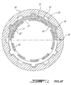
- the improved key washer of the present invention As hereinshown it is also constructed as a flat metal ring 21 but instead of external projecting legs formed on its outer circumferential edge 22', the edge 22' is itself formed with a plurality of straight flat sections 22, herein twelve flat sections, disposed in a side-by-side relationship all around the key washer.
- the coupling disk 16 has an inner surface 23 which is provided with six mating flat surface sections 24 for receiving thereagainst six of the straight flat sections 22 of the key washer 20. Accordingly, the stress concentration factor is greatly reduced on the mating parts due to the smooth geometry.
- Another advantage of such improved key washer is that it results in a cost saving in the manufacture of the coupling disk.
- the inner circumferential edge 25 is also provided with internal projecting legs 26 which locate within the slots 18 of the tie shaft nut 27.
- Figure 2B shows a modification of the key washer 20 wherein the inner circumferential edge 25 may also be formed with straight flat sections 28 offset from the flat sections 22 formed on the outer peripheral edge of the ring.
- the tie shaft nut 27 would then have to be machined to provide flat mating surface sections to co-act therewith.
- Figure 2C is a side view of the ring to illustrate the flatness thereof as well as the disposition of the straight flat sections 22.
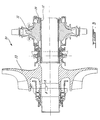
- FIG 3 is a simplified section view showing a high pressure rotor assembly 30 of an aircraft turbine engine.
- the high pressure disk assembly 31 is connected to the tie shaft 32 through the nut 18, as better seen from Figure 4, to couple the high pressure compressor assembly 33 to the disk assembly 31.
- the key washer 20 is secured to the tie shaft nut 18 through its projecting legs 26 extending with the slots 18' of the nut 18.
- the nut 18 is coupled to the tie shaft 32 through a threaded connection 34.
- the flat sections 22 are in mating engagement with corresponding flat surface sections 24 formed in the disk.
- a retention clip 36 maintains the key washer captive.
Landscapes
- Engineering & Computer Science (AREA)
- General Engineering & Computer Science (AREA)
- Mechanical Engineering (AREA)
- Turbine Rotor Nozzle Sealing (AREA)
- Structures Of Non-Positive Displacement Pumps (AREA)
- Bolts, Nuts, And Washers (AREA)
Claims (6)
- Sicherungsscheibe (20) in Kombination mit einem Paar konzentrischer Teile (16, 27) zur Verbindung der konzentrischen Teile, wobei die Sicherungsscheibe (20) durch einen flachen Metallring (21) mit einem Umfangsaußenrand (22') und einem Umfangsinnenrand (25) und zwei oder mehrere Ausbildungsmittel (26) in dem Umfangsinnenrand gebildet wird und zum Zusammenfügen mit einem Paßmittel (18) eines inneren (27) der konzentrischen Teile ausgeführt ist, dadurch gekennzeichnet, daß der Umfangsaußenrand (22') mehrere gerade flache Abschnitte (22) zum Paßeingriff mit inneren flachen Flächenabschnitten (24) eines äußeren (16) der konzentrischen Teile aufweist, wobei die flachen Abschnitte (22) in nebeneinanderliegender Beziehung um den gesamten Außenumfangsrad (22') herum angeordnet sind und mehr von den flachen Abschnitten (22) vorgesehen sind als von den inneren flachen Flächenabschnitten des äußeren der konzentrischen Teile, wobei der flache Metallring (21) eine relative Drehung zwischen den konzentrischen Teilen (16, 27) verhindert.
- Sicherungsscheibe nach Anspruch 1, bei der die Ausbildungsmittel (26) voneinander beabstandete vorragende Schenkel (26) sind, die integral mit dem flachen Metallring (21) ausgebildet sind und von dem Umfangsinnenrand (25) ragen.
- Sicherungsscheibe nach Anspruch 2, bei der die vorragenden Schenkel (26) eine rechteckige Konfiguration aufweisen, die kurze Endränder und einen langen geraden Außenendrand definiert.
- Sicherungsscheibe nach Anspruch 1, bei der die Ausbildungsmittel (26) beabstandete gerade flache Abschnitte (28) sind, die nebeneinander entlang dem Umfangsinnenrand (25) angeordnet sind.
- Sicherungsscheibe nach Anspruch 1, bei der der konzentrische Außenteil (16) eine Kupplungsscheibe einer Hochdruckrotoranordnung (30) eines Flugzeugturbinenmotors und der konzentrische Innenteil eine an einer mit einem Hochdruckkompressor (33) verbundenen Kopplungswelle (32) befestigte Kopplungswellenmutter (18) ist.
- Sicherungsscheibe nach Anspruch 1, bei der am Umfangsaußenrand (22') des flachen Metallrings (20) doppelt so viele flache Abschnitte (22) wie flache Flächenabschnitte (24) des äußeren der konzentrischen Teile (16, 27) vorhanden sind.
Applications Claiming Priority (3)
| Application Number | Priority Date | Filing Date | Title |
|---|---|---|---|
| US89453 | 1998-06-03 | ||
| US09/089,453 US6059486A (en) | 1998-06-03 | 1998-06-03 | Flat key washer |
| PCT/CA1999/000473 WO1999063237A1 (en) | 1998-06-03 | 1999-05-27 | Flat key washer |
Publications (2)
| Publication Number | Publication Date |
|---|---|
| EP1084350A1 EP1084350A1 (de) | 2001-03-21 |
| EP1084350B1 true EP1084350B1 (de) | 2002-03-27 |
Family
ID=22217735
Family Applications (1)
| Application Number | Title | Priority Date | Filing Date |
|---|---|---|---|
| EP99922012A Expired - Lifetime EP1084350B1 (de) | 1998-06-03 | 1999-05-27 | Flache sicherungsscheibe |
Country Status (6)
| Country | Link |
|---|---|
| US (1) | US6059486A (de) |
| EP (1) | EP1084350B1 (de) |
| JP (1) | JP2002517675A (de) |
| CA (1) | CA2333959C (de) |
| DE (1) | DE69901105T2 (de) |
| WO (1) | WO1999063237A1 (de) |
Families Citing this family (6)
| Publication number | Priority date | Publication date | Assignee | Title |
|---|---|---|---|---|
| BRPI1009988A2 (pt) * | 2009-04-01 | 2016-03-15 | Siemens Ag | "rotor para uma turbomáquina" |
| DE102011001564A1 (de) | 2011-03-25 | 2012-09-27 | Hugo Benzing Gmbh & Co. Kg | Schraube mit Aufdrehsicherung |
| US8460118B2 (en) | 2011-08-31 | 2013-06-11 | United Technologies Corporation | Shaft assembly for a gas turbine engine |
| US9212556B2 (en) * | 2012-08-21 | 2015-12-15 | United Technologies Corporation | Multifunction positioning lock washer |
| US11021958B2 (en) * | 2018-10-31 | 2021-06-01 | Raytheon Technologies Corporation | Split vernier ring for turbine rotor stack assembly |
| US11306593B2 (en) | 2019-09-03 | 2022-04-19 | Pratt & Whitney Canada Corp. | Key washer for a gas turbine engine |
Family Cites Families (21)
| Publication number | Priority date | Publication date | Assignee | Title |
|---|---|---|---|---|
| US1145256A (en) * | 1914-01-27 | 1915-07-06 | Carl H L Mochow | Bolt-lock. |
| US2548874A (en) * | 1945-10-10 | 1951-04-17 | Westinghouse Electric Corp | Retaining device |
| US2508832A (en) * | 1948-08-28 | 1950-05-23 | Borg Warner | Coupling device |
| DE1031584B (de) * | 1952-02-20 | 1958-06-04 | Ringspann Maurer Kg A | Radialspannelement |
| GB737703A (en) * | 1952-03-19 | 1955-09-28 | Ringspann Ges M B H | An improved elastically deformable radial clamping-element |
| US2675844A (en) * | 1952-04-23 | 1954-04-20 | Illinois Tool Works | Lock washer |
| US2919940A (en) * | 1955-03-30 | 1960-01-05 | Borg Warner | Means for fixing hubs on shafts |
| US3032089A (en) * | 1959-05-07 | 1962-05-01 | Illinois Tool Works | Lock washer |
| US3038456A (en) * | 1961-01-27 | 1962-06-12 | Allis Chalmers Mfg Co | Self-locking nozzle gasket |
| US3875985A (en) * | 1973-04-07 | 1975-04-08 | Koyo Seiko Co | Device for fixing bolts and nuts |
| GB1546152A (en) * | 1976-10-16 | 1979-05-16 | Cross Mfg Co | Couplings |
| US4477228A (en) * | 1982-01-28 | 1984-10-16 | The Boeing Company | Injection molded propeller |
| US4572718A (en) * | 1984-03-29 | 1986-02-25 | General Signal Corporation | Anti-rotation locking assembly |
| DE3712195C1 (de) * | 1987-04-10 | 1988-07-07 | Daimler Benz Ag | Vorrichtung zur Feineinstellung der Drehwinkellage einer Welle zu einem mit dieser gleichachsig Ioesbar verbundenen Bauteil |
| GB2212585A (en) * | 1987-12-17 | 1989-07-26 | Peter Meynell Lucas | Locking washer |
| DE3900797A1 (de) * | 1988-05-07 | 1989-11-16 | Viets Adalbert Dipl Ing | Vorrichtung zum befestigen einer nabe auf einer welle |
| US4911726A (en) * | 1988-09-13 | 1990-03-27 | Rexnord Holdings Inc. | Fastener/retaining ring assembly |
| DE9016232U1 (de) * | 1990-11-29 | 1991-03-21 | Fa. Andreas Stihl, 71336 Waiblingen | Formschlußkupplung für ein Handarbeitsgerät |
| GB9308557D0 (en) * | 1993-04-24 | 1993-06-09 | Rubery Owen Rockwell Ltd | Fasteners |
| US5395194A (en) * | 1993-10-13 | 1995-03-07 | H. Thad Johnson | Convoluted bolt retainer |
| CA2111126C (en) * | 1993-11-04 | 1997-03-25 | Kevin Myszka | Spindle hub spacer interconnection |
-
1998
- 1998-06-03 US US09/089,453 patent/US6059486A/en not_active Expired - Lifetime
-
1999
- 1999-05-27 WO PCT/CA1999/000473 patent/WO1999063237A1/en active IP Right Grant
- 1999-05-27 CA CA002333959A patent/CA2333959C/en not_active Expired - Lifetime
- 1999-05-27 EP EP99922012A patent/EP1084350B1/de not_active Expired - Lifetime
- 1999-05-27 JP JP2000552408A patent/JP2002517675A/ja not_active Ceased
- 1999-05-27 DE DE69901105T patent/DE69901105T2/de not_active Expired - Fee Related
Also Published As
| Publication number | Publication date |
|---|---|
| JP2002517675A (ja) | 2002-06-18 |
| EP1084350A1 (de) | 2001-03-21 |
| CA2333959A1 (en) | 1999-12-09 |
| DE69901105D1 (de) | 2002-05-02 |
| DE69901105T2 (de) | 2002-11-28 |
| US6059486A (en) | 2000-05-09 |
| WO1999063237A1 (en) | 1999-12-09 |
| CA2333959C (en) | 2006-11-28 |
Similar Documents
| Publication | Publication Date | Title |
|---|---|---|
| US4830557A (en) | Self-aligning floating nut fastener | |
| US5871335A (en) | Twist-lock attachment system for a cooling fan and motor | |
| US8246309B2 (en) | Rotor disk for turbomachine fan | |
| EP3022453B1 (de) | Anlaufscheibe | |
| EP1649181A1 (de) | Kombinationssicherungsscheiben- und spindellageranordnung | |
| EP1348066A1 (de) | Verfahren und montagevorrichtung zum zusammenbau von integralen axial eingeschobenen rotorschaufeln | |
| US5796202A (en) | Tie bolt and stacked wheel assembly for the rotor of a rotary machine | |
| CA2575166A1 (en) | Flexible couplings | |
| US6186756B1 (en) | Shaft structure in screw rotor of screw fluid assembly | |
| EP1084350B1 (de) | Flache sicherungsscheibe | |
| US4294562A (en) | Polygon connection of a hub with a shaft | |
| US6309136B1 (en) | Device for locking a mechanical member onto a shaft | |
| US20020164252A1 (en) | Tapered polygon coupling | |
| CA2012953C (en) | Perforated connecting disk for scaffolding elements | |
| US6540617B2 (en) | Flange yoke for a universal joint and a universally jointed shaft | |
| US4863353A (en) | Attaching arrangement | |
| EP0934470A1 (de) | Gewindeeinsatz mit einer schwimmend gelagerten mutter | |
| CN111535867A (zh) | 动力涡轮短轴、涡轴发动机及飞行器 | |
| EP1061233B1 (de) | Gasturbinenrotorverbindung | |
| US8757981B2 (en) | Locking spacer assembly for a turbine engine | |
| KR102498006B1 (ko) | 원심력에 최적화된 접촉면을 갖는 회전자 | |
| EP0748944A2 (de) | Kupplungs- bzw. Zentriervorrichtung zwischen zwei Elementen | |
| CN221074935U (zh) | 一种行星减速机用圆螺母防松装置 | |
| CN211501066U (zh) | 一种叶轮垫片 | |
| WO2016027368A1 (ja) | 円筒状ケース |
Legal Events
| Date | Code | Title | Description |
|---|---|---|---|
| PUAI | Public reference made under article 153(3) epc to a published international application that has entered the european phase |
Free format text: ORIGINAL CODE: 0009012 |
|
| 17P | Request for examination filed |
Effective date: 20001201 |
|
| AK | Designated contracting states |
Kind code of ref document: A1 Designated state(s): DE FR GB IT SE |
|
| GRAG | Despatch of communication of intention to grant |
Free format text: ORIGINAL CODE: EPIDOS AGRA |
|
| 17Q | First examination report despatched |
Effective date: 20010726 |
|
| GRAG | Despatch of communication of intention to grant |
Free format text: ORIGINAL CODE: EPIDOS AGRA |
|
| GRAH | Despatch of communication of intention to grant a patent |
Free format text: ORIGINAL CODE: EPIDOS IGRA |
|
| GRAH | Despatch of communication of intention to grant a patent |
Free format text: ORIGINAL CODE: EPIDOS IGRA |
|
| REG | Reference to a national code |
Ref country code: GB Ref legal event code: IF02 |
|
| GRAA | (expected) grant |
Free format text: ORIGINAL CODE: 0009210 |
|
| AK | Designated contracting states |
Kind code of ref document: B1 Designated state(s): DE FR GB IT SE |
|
| PG25 | Lapsed in a contracting state [announced via postgrant information from national office to epo] |
Ref country code: IT Free format text: LAPSE BECAUSE OF FAILURE TO SUBMIT A TRANSLATION OF THE DESCRIPTION OR TO PAY THE FEE WITHIN THE PRESCRIBED TIME-LIMIT;WARNING: LAPSES OF ITALIAN PATENTS WITH EFFECTIVE DATE BEFORE 2007 MAY HAVE OCCURRED AT ANY TIME BEFORE 2007. THE CORRECT EFFECTIVE DATE MAY BE DIFFERENT FROM THE ONE RECORDED. Effective date: 20020327 |
|
| REF | Corresponds to: |
Ref document number: 69901105 Country of ref document: DE Date of ref document: 20020502 |
|
| PG25 | Lapsed in a contracting state [announced via postgrant information from national office to epo] |
Ref country code: SE Free format text: LAPSE BECAUSE OF FAILURE TO SUBMIT A TRANSLATION OF THE DESCRIPTION OR TO PAY THE FEE WITHIN THE PRESCRIBED TIME-LIMIT Effective date: 20020627 |
|
| ET | Fr: translation filed | ||
| PLBE | No opposition filed within time limit |
Free format text: ORIGINAL CODE: 0009261 |
|
| STAA | Information on the status of an ep patent application or granted ep patent |
Free format text: STATUS: NO OPPOSITION FILED WITHIN TIME LIMIT |
|
| 26N | No opposition filed |
Effective date: 20021230 |
|
| PGFP | Annual fee paid to national office [announced via postgrant information from national office to epo] |
Ref country code: DE Payment date: 20080530 Year of fee payment: 10 |
|
| PG25 | Lapsed in a contracting state [announced via postgrant information from national office to epo] |
Ref country code: DE Free format text: LAPSE BECAUSE OF NON-PAYMENT OF DUE FEES Effective date: 20091201 |
|
| REG | Reference to a national code |
Ref country code: FR Ref legal event code: PLFP Year of fee payment: 18 |
|
| REG | Reference to a national code |
Ref country code: FR Ref legal event code: PLFP Year of fee payment: 19 |
|
| REG | Reference to a national code |
Ref country code: FR Ref legal event code: PLFP Year of fee payment: 20 |
|
| PGFP | Annual fee paid to national office [announced via postgrant information from national office to epo] |
Ref country code: FR Payment date: 20180423 Year of fee payment: 20 |
|
| PGFP | Annual fee paid to national office [announced via postgrant information from national office to epo] |
Ref country code: GB Payment date: 20180419 Year of fee payment: 20 |
|
| REG | Reference to a national code |
Ref country code: GB Ref legal event code: PE20 Expiry date: 20190526 |
|
| PG25 | Lapsed in a contracting state [announced via postgrant information from national office to epo] |
Ref country code: GB Free format text: LAPSE BECAUSE OF EXPIRATION OF PROTECTION Effective date: 20190526 |