EP1193186A2 - Device for the reversible fixation of a container on a support and container equipped with such a device - Google Patents
Device for the reversible fixation of a container on a support and container equipped with such a device Download PDFInfo
- Publication number
- EP1193186A2 EP1193186A2 EP01402120A EP01402120A EP1193186A2 EP 1193186 A2 EP1193186 A2 EP 1193186A2 EP 01402120 A EP01402120 A EP 01402120A EP 01402120 A EP01402120 A EP 01402120A EP 1193186 A2 EP1193186 A2 EP 1193186A2
- Authority
- EP
- European Patent Office
- Prior art keywords
- container
- support
- suction cup
- openings
- sleeve
- Prior art date
- Legal status (The legal status is an assumption and is not a legal conclusion. Google has not performed a legal analysis and makes no representation as to the accuracy of the status listed.)
- Granted
Links
- 230000002441 reversible effect Effects 0.000 title description 3
- 238000002347 injection Methods 0.000 claims abstract description 13
- 239000007924 injection Substances 0.000 claims abstract description 13
- 239000002537 cosmetic Substances 0.000 claims abstract description 8
- 239000000463 material Substances 0.000 claims description 32
- -1 polyethylene Polymers 0.000 claims description 19
- 239000004698 Polyethylene Substances 0.000 claims description 10
- 229920000573 polyethylene Polymers 0.000 claims description 10
- 239000000203 mixture Substances 0.000 claims description 9
- 238000006555 catalytic reaction Methods 0.000 claims description 8
- 239000000443 aerosol Substances 0.000 claims description 6
- 238000007789 sealing Methods 0.000 claims description 6
- 229920002614 Polyether block amide Polymers 0.000 claims description 5
- 239000004433 Thermoplastic polyurethane Substances 0.000 claims description 5
- 229920002803 thermoplastic polyurethane Polymers 0.000 claims description 5
- 239000004743 Polypropylene Substances 0.000 claims description 4
- 239000013536 elastomeric material Substances 0.000 claims description 4
- 229920001155 polypropylene Polymers 0.000 claims description 4
- VGGSQFUCUMXWEO-UHFFFAOYSA-N Ethene Chemical compound C=C VGGSQFUCUMXWEO-UHFFFAOYSA-N 0.000 claims description 3
- 229920000139 polyethylene terephthalate Polymers 0.000 claims description 3
- 239000005020 polyethylene terephthalate Substances 0.000 claims description 3
- QQONPFPTGQHPMA-UHFFFAOYSA-N propylene Natural products CC=C QQONPFPTGQHPMA-UHFFFAOYSA-N 0.000 claims description 3
- 239000005977 Ethylene Substances 0.000 claims description 2
- 239000002174 Styrene-butadiene Substances 0.000 claims description 2
- MTAZNLWOLGHBHU-UHFFFAOYSA-N butadiene-styrene rubber Chemical compound C=CC=C.C=CC1=CC=CC=C1 MTAZNLWOLGHBHU-UHFFFAOYSA-N 0.000 claims description 2
- 229920001577 copolymer Polymers 0.000 claims description 2
- 150000001993 dienes Chemical class 0.000 claims description 2
- 229920001971 elastomer Polymers 0.000 claims description 2
- 239000000806 elastomer Substances 0.000 claims description 2
- 230000003100 immobilizing effect Effects 0.000 claims description 2
- 238000004519 manufacturing process Methods 0.000 claims description 2
- 238000000034 method Methods 0.000 claims description 2
- 125000004805 propylene group Chemical group [H]C([H])([H])C([H])([*:1])C([H])([H])[*:2] 0.000 claims description 2
- 239000011115 styrene butadiene Substances 0.000 claims description 2
- 229920003048 styrene butadiene rubber Polymers 0.000 claims description 2
- 230000002093 peripheral effect Effects 0.000 abstract description 5
- 238000001746 injection moulding Methods 0.000 abstract 1
- 230000000694 effects Effects 0.000 description 9
- 238000004806 packaging method and process Methods 0.000 description 3
- 238000009826 distribution Methods 0.000 description 2
- 229920003031 santoprene Polymers 0.000 description 2
- 239000000243 solution Substances 0.000 description 2
- 239000007921 spray Substances 0.000 description 2
- 229910052782 aluminium Inorganic materials 0.000 description 1
- XAGFODPZIPBFFR-UHFFFAOYSA-N aluminium Chemical compound [Al] XAGFODPZIPBFFR-UHFFFAOYSA-N 0.000 description 1
- 150000001408 amides Chemical class 0.000 description 1
- 230000006835 compression Effects 0.000 description 1
- 238000007906 compression Methods 0.000 description 1
- 230000006866 deterioration Effects 0.000 description 1
- 238000009792 diffusion process Methods 0.000 description 1
- 239000006260 foam Substances 0.000 description 1
- 239000000499 gel Substances 0.000 description 1
- 239000008266 hair spray Substances 0.000 description 1
- 238000009776 industrial production Methods 0.000 description 1
- 239000004922 lacquer Substances 0.000 description 1
- 229910052751 metal Inorganic materials 0.000 description 1
- 239000002184 metal Substances 0.000 description 1
- 238000000465 moulding Methods 0.000 description 1
- 230000000284 resting effect Effects 0.000 description 1
- 239000002453 shampoo Substances 0.000 description 1
- 239000000344 soap Substances 0.000 description 1
- 239000007787 solid Substances 0.000 description 1
- 239000012815 thermoplastic material Substances 0.000 description 1
- 239000005028 tinplate Substances 0.000 description 1
- 238000003466 welding Methods 0.000 description 1
Images


Classifications
-
- B—PERFORMING OPERATIONS; TRANSPORTING
- B65—CONVEYING; PACKING; STORING; HANDLING THIN OR FILAMENTARY MATERIAL
- B65D—CONTAINERS FOR STORAGE OR TRANSPORT OF ARTICLES OR MATERIALS, e.g. BAGS, BARRELS, BOTTLES, BOXES, CANS, CARTONS, CRATES, DRUMS, JARS, TANKS, HOPPERS, FORWARDING CONTAINERS; ACCESSORIES, CLOSURES, OR FITTINGS THEREFOR; PACKAGING ELEMENTS; PACKAGES
- B65D25/00—Details of other kinds or types of rigid or semi-rigid containers
- B65D25/20—External fittings
- B65D25/24—External fittings for spacing bases of containers from supporting surfaces, e.g. legs
Definitions
- the present invention relates to the field of containers, in particular of the type aerosol containers, pump containers, vials, or tubes, as used commonly, especially for the packaging of cosmetic products, such than hair products (hairsprays, styling foams, gels, shampoos, etc.). More specifically, the invention relates to a device capable of reducing the risk such containers fall, when they are placed upright on a support, including plan.
- Such a device when produced by injection, requires having the injection point located on the periphery of the object, that is to say substantially offset by relation to the geometric center of the suction cup device. Therefore, it Opposite the injection point, a weld line results, which line of welding constitutes a zone of weakness.
- the problem is all the more critical when the material forming the device is a flexible material, and when the device is intended to work under constant mechanical stress (in particular by elastic clamping).
- a solution to the problem mentioned above consists in making the device in the form of a cylindrical skirt of which a first end is open, and of which a second end, opposite the first, has a closed bottom. Arises then the problem of demolding the device automatically, the latter forming suction cup effect on the mold core, to the point that it is difficult to separate it from the core.
- Document DE 31 44 061 A1 describes a tube, in particular of a cosmetic product the plug of which is configured so as to form a suction cup. Such a solution forces the container to be immobilized upside down, which for many of products, is not desirable. In addition, essentially arises the same problem than that mentioned with reference to document US-A-2,908,473.
- Document US-A-2 968 888 describes a support for objects such as soaps or drinks, comprising a part intended to receive said object, and a suction cup part.
- the suction cup is formed in its entirety by a part of the support.
- the support acts as a suction cup, regardless of the presence or absence of the object it is intended to receive.
- support handling problems especially on the production lines or industrial packaging.
- the suction cup tends to adhere on any surface it meets.
- the solid surface forming a suction cup also tending to adhere to the mold surface.
- a device for reversibly immobilize a container, in particular a cosmetic product, on a support (S) said device comprising a portion for mounting the device on the container and a perforated bottom including an edge, in particular peripheral, forms a lip capable of being applied in a sealed manner on the support (S), so as, in cooperation with a portion of the container, to form a suction cup on the support (S), and immobilize the container reversibly on said support (S), said openwork bottom defining at least one opening, each of said openings extending away from the geometric center of said background.
- the geometric center means the geometric center or barycenter of the section transverse of the bottom of the device.
- a bottom is of section circular.
- the "suction cup” effect designates the depression generated inside a volume whose a reduction is caused, in particular by compression, thus driving out a corresponding air volume, which, in particular by elastic return of the material forming the walls which delimit it at least in part, tends to resume its state initial in a waterproof universe.
- the demolding of the device is not a problem. Indeed, it is only when the device is mounted on the container that it is able to form a suction cup.
- the injection of the material constituting the device can be done via said geometric center, which allows the material, when injected into the mold, to distribute uniformly and simultaneously all around the injection site without forming weld line subject to break when the device is under mechanical stress permed.
- the mounting of the device on the container for which it is intended is at the both simple and effective. It does not require any special tool.
- the assembly of the device on the container is reversible, which allows successive use of the same device for multiple containers.
- the adjustment of the different device parameters depends to a large extent on the dimensions of the container to be fitted, the surface condition of its outer walls, the solidity required for hanging of the container on the support. Still other elements can be taken into account. consideration for the determination of these performance parameters.
- the mounting portion comprises a sleeve of which a free edge delimits an opening through which the device is intended to be mounted on the container, one end of the sleeve opposite the free edge forming said perforated bottom. Maintaining the device on the container can be obtained by tightening, in particular elastic, the sleeve on the container.
- the openwork bottom delimits at least two openings.
- the presence of at least two openings creates a "symmetry" around the geometric center. When the latter is used as an injection point, the material is distributed much more evenly, which improves the mechanical resistance of the device.
- said sleeve is able to grip, in particular by tightening elastic, the container over part of its axial height. Typically, such height is of the order of a few centimeters.
- the sleeve could be glued, snapped or screwed onto the container.
- the bottom delimits three separate openings by three legs or bridges of material spaced regularly, and arranged at 120 ° relative to each other.
- the bottom delimits four separate openings by four legs or bridges of material spaced regularly, and arranged at 90 ° to each other. The more the number of legs or bridges of material the greater the risk of generating lines of weakness, the lower the risk.
- the device is made at least partly of a material elastomeric whose hardness is between 20 Shore A and 40 Shore D, and preferably between 40 Shore A and 75 Shore A, and the elasticity between 0.5 to 5 MPa, and preferably 0.8 to 2 MPa (tensile stress at 100% elongation).
- a material elastomeric whose hardness is between 20 Shore A and 40 Shore D, and preferably between 40 Shore A and 75 Shore A, and the elasticity between 0.5 to 5 MPa, and preferably 0.8 to 2 MPa (tensile stress at 100% elongation).
- said elastomeric material is a mixture formed in part of a metallocene catalysis polyethylene, in particular a polyethylene of very low density catalysis.
- a mixture formed from such a material in combination with a other base material, examples of which will be given below, allows a automatic demolding of the device.
- the hardness and elasticity of the material base, with which the metallocene catalysis polyethylene is mixed, are not significantly altered, so that the functionality of the device molding remains as good.
- the tear resistance is improved significantly compared to that of the base material (s).
- the appearance properties of the base material in particular its transparency or color, are unchanged.
- said mixture contains from 5 to 30% of said catalyzed polyethylene metallocene, and preferably from 10 to 20%.
- a very low density catalysis polyethylene 902
- EXACT TM very low density catalysis polyethylene
- the container comprises a body, one end of which ends by a bottom, the portion of the container suitable, in combination with the device, for form a suction cup, consisting of all or part of said bottom of the container.
- the part of the container capable, in combination with the immobilizer, to form a suction cup is constituted all or part of the plug.
- the immobilization device is formed in one piece, made in the same elastomeric material, and obtained by injection of said material elastomeric.
- the sealing lip when it is applied to the support (S), has an outside diameter greater than or equal to the outside diameter of the body of the container. This ensures better stability of the container.
- the bottom of the device has a profile, in particular concave, capable of follow the profile of the bottom of the container.
- a concave bottom corresponds to a common configuration for aerosol containers, in particular for reasons of resistance to pressure inside the container.
- a container is also produced, especially a cosmetic product, equipped with a suction cup device according to the invention.
- a container comprises a body forming a reservoir for said product, and one end of which is closed by a bottom, said bottom, in cooperation with the device, being able to form a suction cup on a support (S).
- Such a container can be formed of a tube, a bottle, a pump container, or an aerosol container, in particular for hair product.
- the resulting part shows a perfect distribution of the material, and is free from brittle lines subject to rupture when the part is under stress mechanical.
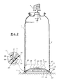
- FIG 2 there is shown an aerosol container 1 resting on a flat surface S, including a worktop in a hair salon.
- Container 1 includes a cylindrical body 2, surmounted by a valve 3.
- the valve is equipped a push button 4, able to allow its actuation and the diffusion of the produced through, in particular, an outlet nozzle.
- the product can be a lacquer styling or spray.
- the end of the container 1, opposite the valve 3, is closed by an attached base 5 which, for reasons of resistance to pressure prevailing inside the container, is concave in shape.
- the container can be made in thermoplastic material, in particular in PET or in metal, in particular in aluminum or tinplate.
- a device is mounted on the bottom of the container invention 10, the function of which is, as will now be seen in detail, to prevent the container 1 from spilling on the surface S.
- the device will now be described in detail with reference to FIG. 1, which shows the assembly of FIG. 2 in an exploded manner, as well as with reference to Figure 3.
- the device 10 is an element obtained by injecting a material including 20% EXACT TM and 80% Santoprene TM.
- the device is opaque, white in color.
- the device is in the form of a cylindrical sleeve of revolution 11, one end of which has a free edge 12 delimiting an opening 13 so as to allow the mounting of the container 10 of the manner illustrated in FIG. 2.
- the internal diameter of the sleeve 11 is, in the absence of stress, slightly lower (of the order of 1 to several mm in material elasticity) to the outside diameter of the container 1 of so as to allow a tight fitting of the sleeve 11 on the body 2 of the container 1.
- the thickness of the walls of the device 10 is approximately 1 mm.
- the end of the sleeve, opposite the end of the opening 13 has a bottom 14 of circular cross section.
- the bottom 14 has an annular portion 15, of concave profile, similar to the profile of the bottom 5 of the container 1, and intended, in position mounted on the container, to match the profile of an annular part correspondent of the bottom 5, with which it comes in intimate engagement.
- AT the interior of the annular portion 15 is formed a cross part 16, constituted four legs 17, 18, 19, 20, arranged at 90 ° to each other, and delimiting four openings 21, 22, 23, 24.
- the geometric center of the bottom 14 is located at the junction 25 of the four legs 17-20, and, therefore, is at a distance from the openings 21-24.
- the annular element 15 forms at its periphery an annular sealing lip 26, larger in diameter (for example, about 5 mm) than the outside diameter of the sleeve 11.
- a surface 27 of the sealing lip 26 is intended to be tightly applied to the support S.
- the surface 27 of the lip 26 forms a curvature of the same orientation as the curvature formed by the annular portion 15 from the bottom 14.
- the sealing lip 27 is separated from the internal annular wall 15 by an intermediate annular portion 28, forming a U-shaped groove, intended to receive the peripheral edge of the container 1.
- the suction cup device 10 appears in more detail in Figures 1 and 3. In these figures, the device 10 is not mounted on a container.
- the device 10 is mounted on the container 1 by inserting the bottom of the container 1 through the opening 13 of the sleeve 11, and this, until the peripheral edge of the container 1 comes into engagement in the bottom of the groove in U, 28 of the device 10.
- a tongue (not shown) can extend the free edge 12 of the sleeve 11 so as to form a grip zone to facilitate the mounting the device 10 on the container 1.
- the sleeve 11 is slightly tightening on the body 2 of the container. The tightening achieved by the sleeve 11 on the body 2 of the container, ensures good hold of the device 10 on the container 1.
- the operator After mounting the device 10 on the container 1, the operator supports the surface 27 on the support S, thus causing deformation of the lip sealing 26, and the expulsion of a corresponding volume of air.
- the deformed portion of the lip 26 tends to return to its initial shape, despite of the seal prevailing inside the volume delimited by the support S, the bottom 14 of the device 10, and the central part of the bottom 5 of the container 1. This creates a depression inside said volume, which depression generates the suction effect suitable for reversibly immobilizing the container 1 on the support S.
- the operator grasps it by the body 2, and rotates it by direction of the support S.
- the behavior of the device 10 on the support being less than the clamping force of the device 10 on the container, the wall 27 of the lip 26 of the device 10 comes off the support.
- Device 10 remains integral with the container 1. The latter can then be used in a conventional manner.
Abstract
Description
La présente invention concerne le domaine des récipients, notamment du type récipients aérosols, récipients à pompe, flacons, ou tubes, tel qu'utilisés couramment, notamment pour le conditionnement de produits cosmétiques, tels que les produits capillaires (laques, mousses coiffantes, gels, shampooings, etc.). De manière plus précise, l'invention concerne un dispositif apte à réduire le risque de chute de tels récipients, lorsque ceux-ci sont disposés debout sur un support, notamment plan.The present invention relates to the field of containers, in particular of the type aerosol containers, pump containers, vials, or tubes, as used commonly, especially for the packaging of cosmetic products, such than hair products (hairsprays, styling foams, gels, shampoos, etc.). More specifically, the invention relates to a device capable of reducing the risk such containers fall, when they are placed upright on a support, including plan.
Bon nombre de produits cosmétiques sont conditionnés dans des récipients dont le dimensionnel est tel que, leur "renversabilité", lorsqu'ils sont posés sur un plan de travail par exemple, est relativement importante. En effet, de tels conditionnements sont de forme généralement cylindrique, et sont de hauteur relativement importante, comparativement à leur section transversale. Cette "renversabilité" est perçue comme un problème sensible, notamment dans le monde des salons de coiffure, grand consommateur de tels conditionnements. Dans cet univers, où les cordons d'alimentation des sèches cheveux "volent" au dessus des plans de travail sur lesquels sont posés les sprays ou autres récipients aérosols, les chutes sont fréquentes. Outre le bruit occasionné par de telles chutes, le risque de détérioration du récipient, notamment de son système de distribution, n'est pas inexistant.Many cosmetic products are packaged in containers, the dimension is such that, their "reversibility", when placed on a plane work for example is relatively large. Indeed, such packages are generally cylindrical in shape, and are tall relatively large compared to their cross section. This "reversibility" is perceived as a sensitive problem, particularly in the world of hairdressing salons, major consumer of such packaging. In this universe, where the power cords of hair dryers "fly" at above the work surfaces on which the sprays or other containers are placed aerosols, falls are frequent. In addition to the noise caused by such the risk of deterioration of the container, in particular of its distribution, is not inexistent.
On connaít du document US-A-2 908 473, une bouteille, notamment de vernis à ongles, dont le fond est équipé d'un dispositif d'immobilisation sous forme d'un élément annulaire dont une lèvre périphérique est apte à former ventouse.We know from document US-A-2 908 473, a bottle, in particular of nails, the bottom of which is equipped with an immobilization device in the form of a annular element of which a peripheral lip is capable of forming a suction cup.
Un tel dispositif, lorsqu'il est réalisé par injection, oblige à avoir le point d'injection situé en périphérie de l'objet, c'est à dire de manière sensiblement décalée par rapport au centre géométrique du dispositif formant ventouse. De ce fait, il en résulte, à l'opposé du point d'injection, une ligne de soudure, laquelle ligne de soudure constitue une zone de fragilité. Le problème est d'autant plus critique lorsque le matériau formant le dispositif est un matériau souple, et lorsque le dispositif est destiné à travailler sous contrainte mécanique constante (notamment par serrage élastique).Such a device, when produced by injection, requires having the injection point located on the periphery of the object, that is to say substantially offset by relation to the geometric center of the suction cup device. Therefore, it Opposite the injection point, a weld line results, which line of welding constitutes a zone of weakness. The problem is all the more critical when the material forming the device is a flexible material, and when the device is intended to work under constant mechanical stress (in particular by elastic clamping).
Une solution au problème évoqué précédemment consiste à réaliser le dispositif sous forme d'une jupe cylindrique dont une première extrémité est ouverte, et dont une seconde extrémité, opposée à la première, comporte un fond fermé. Se pose alors le problème du démoulage du dispositif en automatique, celui-ci formant en effet ventouse sur le noyau du moule, au point qu'il est difficile de le séparer du noyau.A solution to the problem mentioned above consists in making the device in the form of a cylindrical skirt of which a first end is open, and of which a second end, opposite the first, has a closed bottom. Arises then the problem of demolding the device automatically, the latter forming suction cup effect on the mold core, to the point that it is difficult to separate it from the core.
Le document DE 31 44 061 A1 décrit un tube, notamment de produit cosmétique dont le bouchon est configuré de manière à former ventouse. Une telle solution oblige à immobiliser le récipient en position tête en bas, ce qui pour bon nombre de produits, n'est pas souhaitable. En outre, se pose essentiellement le même problème que celui évoqué en référence au document US-A-2 908 473.Document DE 31 44 061 A1 describes a tube, in particular of a cosmetic product the plug of which is configured so as to form a suction cup. Such a solution forces the container to be immobilized upside down, which for many of products, is not desirable. In addition, essentially arises the same problem than that mentioned with reference to document US-A-2,908,473.
Des documents US-A-4 955 493 et US-A 4 756 497, sont connus des dispositifs d'immobilisation à effet ventouse, réalisés en au moins deux pièces montées l'une sur l'autre. De tels dispositifs sont coûteux à réaliser, et relativement complexes à positionner sur le récipient auquel ils sont destinés.Documents US-A-4,955,493 and US-A 4,756,497 are known to the devices immobilizer with suction cup effect, made of at least two pieces mounted one on the other. Such devices are expensive to produce, and relatively complex to position on the container for which they are intended.
Le document US-A-2 968 888 décrit un support pour des objets tels que des savons ou des boissons, comprenant une partie destinée à recevoir ledit objet, et une partie formant ventouse. La ventouse est formée dans son intégralité par une partie du support. Ainsi, le support fait office de ventouse, indépendamment de la présence ou non de l'objet qu'il est destiné à recevoir. Se posent alors des problèmes de manipulation du support, notamment sur les chaínes de fabrication ou de conditionnement industrielles. En effet, la ventouse a tendance à adhérer sur toute surface qu'elle rencontre. En outre, se pose également le problème du démoulage, la surface pleine formant ventouse ayant également tendance à adhérer à la surface du moule. Document US-A-2 968 888 describes a support for objects such as soaps or drinks, comprising a part intended to receive said object, and a suction cup part. The suction cup is formed in its entirety by a part of the support. Thus, the support acts as a suction cup, regardless of the presence or absence of the object it is intended to receive. Then arise support handling problems, especially on the production lines or industrial packaging. Indeed, the suction cup tends to adhere on any surface it meets. In addition, there is also the problem of demolding, the solid surface forming a suction cup also tending to adhere to the mold surface.
Aussi, est-ce un des objets de l'invention que de réaliser un dispositif d'immobilisation réversible d'un récipient sur un support, et qui résolve en tout ou partie les inconvénients discutés en référence aux documents cités ci-avant.Also, is it an object of the invention to make a device reversible immobilization of a container on a support, and which resolves all or part of the drawbacks discussed with reference to the documents cited above.
C'est en particulier un objet de l'invention que de réaliser un tel dispositif, qui puisse être fabriqué par injection, et qui résiste aux contraintes mécaniques nécessaires à son montage et à son maintien sur le récipient auquel il est destiné.It is in particular an object of the invention to produce such a device, which can be manufactured by injection, and which withstands mechanical stress necessary for mounting and maintaining it on the container for which it is intended.
C'est un autre objet de l'invention que de fournir un dispositif permettant d'améliorer la stabilité d'un récipient de manière significative, sans avoir à modifier le récipient en lui même.It is another object of the invention to provide a device allowing significantly improve the stability of a container without having to modify the container itself.
C'est encore un autre objet de la présente invention que de fournir un tel dispositif qui soit simple et économique à réaliser.It is yet another object of the present invention to provide such a device which is simple and economical to produce.
C'est un autre objet encore de l'invention que de fournir un récipient à stabilité améliorée, équipée d'un dispositif selon l'invention.It is yet another object of the invention to provide a stable container improved, equipped with a device according to the invention.
D'autres objets encore apparaítront dans la description détaillée qui suit.Still other objects will appear in the detailed description which follows.
Selon l'invention, ces objets sont atteints en réalisant un dispositif pour immobiliser de façon réversible, un récipient, notamment de produit cosmétique, sur un support (S), ledit dispositif comprenant une portion pour le montage du dispositif sur le récipient et un fond ajouré dont un bord, notamment périphérique, forme une lèvre apte à s'appliquer de manière étanche sur le support (S), de manière à, en coopération avec une portion du récipient, former ventouse sur le support (S), et immobiliser de façon réversible le récipient sur ledit support (S), ledit fond ajouré délimitant au moins une ouverture, chacune desdites ouvertures s'étendant à distance du centre géométrique dudit fond.According to the invention, these objects are achieved by producing a device for reversibly immobilize a container, in particular a cosmetic product, on a support (S), said device comprising a portion for mounting the device on the container and a perforated bottom including an edge, in particular peripheral, forms a lip capable of being applied in a sealed manner on the support (S), so as, in cooperation with a portion of the container, to form a suction cup on the support (S), and immobilize the container reversibly on said support (S), said openwork bottom defining at least one opening, each of said openings extending away from the geometric center of said background.
Le centre géométrique s'entend du centre géométrique ou barycentre de la section transversale du fond du dispositif. De préférence, un tel fond est de section circulaire. The geometric center means the geometric center or barycenter of the section transverse of the bottom of the device. Preferably, such a bottom is of section circular.
L'effet de " ventouse" désigne la dépression générée à l'intérieur d'un volume dont on provoque une réduction, notamment par compression, chassant ainsi un volume d'air correspondant, et qui, notamment par rappel élastique du matériau formant les parois qui le délimitent au moins en partie, tend à reprendre son état initial dans un univers étanche.The "suction cup" effect designates the depression generated inside a volume whose a reduction is caused, in particular by compression, thus driving out a corresponding air volume, which, in particular by elastic return of the material forming the walls which delimit it at least in part, tends to resume its state initial in a waterproof universe.
Ainsi, en raison de la (ou des) ouverture(s) qui traverse(nt) le fond, le démoulage du dispositif ne pose pas de problème. En effet, ce n'est que quand le dispositif est monté sur le récipient qu'il est apte à former ventouse. En outre, en raison de la portion non ajourée en regard du centre géométrique du fond, l'injection du matériau constituant le dispositif peut se faire via ledit centre géométrique, ce qui permet à la matière, lorsqu'elle est injectée dans le moule, de se répartir de manière uniforme et simultanément tout autour du point d'injection sans former de ligne de soudure sujette à rupture lorsque le dispositif est en contrainte mécanique permanente.Thus, due to the opening (s) which cross (es) the bottom, the demolding of the device is not a problem. Indeed, it is only when the device is mounted on the container that it is able to form a suction cup. In addition, due to the non-perforated portion opposite the geometric center of the bottom, the injection of the material constituting the device can be done via said geometric center, which allows the material, when injected into the mold, to distribute uniformly and simultaneously all around the injection site without forming weld line subject to break when the device is under mechanical stress permed.
Par ailleurs, le montage du dispositif sur le récipient auquel il est destiné, est à la fois simple et efficace. Il ne nécessite aucun outil particulier. Le montage du dispositif sur le récipient est réversible, ce qui rend possible l'utilisation successive du même dispositif pour de multiples récipients. L'ajustement des différents paramètres du dispositif (notamment ses dimensions et le choix du matériau utilisé) dépend dans une large mesure des dimensions du récipient à équiper, de l'état de surface de ses parois extérieures, de la solidité requise pour l'accrochage du récipient sur le support. D'autres éléments encore peuvent être pris en considération en vue de la détermination de ces paramètres de réalisation.Furthermore, the mounting of the device on the container for which it is intended, is at the both simple and effective. It does not require any special tool. The assembly of the device on the container is reversible, which allows successive use of the same device for multiple containers. The adjustment of the different device parameters (including dimensions and choice of material used) depends to a large extent on the dimensions of the container to be fitted, the surface condition of its outer walls, the solidity required for hanging of the container on the support. Still other elements can be taken into account. consideration for the determination of these performance parameters.
Le fait d'utiliser une partie du récipient, notamment le fond, pour délimiter en partie le volume dans lequel est réalisé l'effet ventouse, (par opposition à une ventouse qui serait délimitée dans son intégralité par le dispositif) permet de réduire de manière sensible la quantité de matériau nécessaire pour la réalisation d'un tel dispositif, améliorant ainsi de façon sensible le coût de revient du dispositif. En outre, ce n'est qu'une fois monté sur l'objet à stabiliser que le dispositif est apte à se fixer, par effet ventouse, sur un support avec lequel il est mis en contact. De ce fait, outre le démoulage, la manipulation du dispositif, notamment sur des chaínes de production industrielle peut s'en trouver facilitée. Enfin, l'effet ventouse sur le support n'étant obtenu que par la continuité du dispositif avec la portion correspondante du récipient, toute propension du récipient à se séparer du dispositif d'immobilisation supprime cette continuité, et par la même l'effet ventouse. Dans ces conditions, le dispositif formant ventouse ne peut donc pas se séparer du récipient.The fact of using a part of the container, in particular the bottom, to delimit in part the volume in which the suction cup effect is achieved, (as opposed to a suction cup which would be delimited in its entirety by the device) makes it possible to reduce appreciably the amount of material necessary for the realization of such device, thereby significantly improving the cost price of the device. In furthermore, it is only once mounted on the object to be stabilized that the device is able to to be fixed, by suction effect, on a support with which it is brought into contact. From this makes, in addition to demolding, the manipulation of the device, in particular on chains industrial production can be facilitated. Finally, the suction cup effect on the support being obtained only by the continuity of the device with the portion container, any propensity for the container to separate from the immobilizer removes this continuity, and by the same token the effect suction cup. Under these conditions, the suction cup device cannot therefore be separate from container.
Selon un mode de réalisation préférentiel, la portion de montage comprend un manchon dont un bord libre délimite une ouverture au travers de laquelle le dispositif est destiné à être monté sur le récipient, une extrémité du manchon opposée au bord libre formant ledit fond ajouré. Le maintien du dispositif sur le récipient peut être obtenu par serrage, notamment élastique, du manchon sur le récipient.According to a preferred embodiment, the mounting portion comprises a sleeve of which a free edge delimits an opening through which the device is intended to be mounted on the container, one end of the sleeve opposite the free edge forming said perforated bottom. Maintaining the device on the container can be obtained by tightening, in particular elastic, the sleeve on the container.
De manière très préférentielle, le fond ajouré délimite au moins deux ouvertures. La présence d'au moins deux ouvertures permet de créer une "symétrie" autour du centre géométrique. Ainsi, lorsque ce dernier est utilisé comme point d'injection, la matière se répartit de manière beaucoup plus uniforme, ce qui améliore d'autant la résistance mécanique du dispositif.Very preferably, the openwork bottom delimits at least two openings. The presence of at least two openings creates a "symmetry" around the geometric center. When the latter is used as an injection point, the material is distributed much more evenly, which improves the mechanical resistance of the device.
De préférence, ledit manchon est apte à enserrer, notamment par serrage élastique, le récipient sur une partie de sa hauteur axiale. Typiquement, une telle hauteur est de l'ordre de quelques centimètres. Alternativement, le manchon pourrait être collé, encliqueté ou vissé sur le récipient.Preferably, said sleeve is able to grip, in particular by tightening elastic, the container over part of its axial height. Typically, such height is of the order of a few centimeters. Alternatively, the sleeve could be glued, snapped or screwed onto the container.
Selon un mode de réalisation possible, le fond délimite trois ouvertures, séparées par trois pattes ou ponts de matière espacés de manière régulière, et disposés à 120° les uns par rapport aux autres.According to a possible embodiment, the bottom delimits three separate openings by three legs or bridges of material spaced regularly, and arranged at 120 ° relative to each other.
Toutefois, de manière préférentielle, le fond délimite quatre ouvertures séparées par quatre pattes ou ponts de matière espacés de manière régulière, et disposés à 90° les uns par rapport aux autres. Plus le nombre de pattes ou ponts de matière est grand, et plus les risques de générer des lignes de fragilité sont faibles. However, preferably, the bottom delimits four separate openings by four legs or bridges of material spaced regularly, and arranged at 90 ° to each other. The more the number of legs or bridges of material the greater the risk of generating lines of weakness, the lower the risk.
De préférence, le dispositif est réalisé au moins pour partie en un matériau élastomérique dont la dureté est comprise entre 20 Shore A et 40 Shore D, et de préférence, entre 40 Shore A et 75 Shore A, et l'élasticité comprise entre 0,5 à 5 MPa, et de préférence, de 0,8 à 2 MPa (contrainte de traction à 100 % d'allongement).Preferably, the device is made at least partly of a material elastomeric whose hardness is between 20 Shore A and 40 Shore D, and preferably between 40 Shore A and 75 Shore A, and the elasticity between 0.5 to 5 MPa, and preferably 0.8 to 2 MPa (tensile stress at 100% elongation).
Avantageusement, ledit matériau élastomérique est un mélange formé pour partie d'un polyéthylène de catalyse métallocène, notamment un polyéthylène de catalyse de très basse densité. De manière surprenante, la demanderesse a découvert qu'un mélange formé à partir d'un tel matériau, en combinaison avec un autre matériau de base, dont on donnera ci-après des exemples, autorise un démoulage en automatique du dispositif. La dureté et l'élasticité du matériau de base, avec lequel le polyéthylène de catalyse métallocène est mélangé, ne sont pas altérées de manière sensible, de sorte que la fonctionnalité du dispositif issu du moulage reste aussi bonne. En outre, la résistance à la déchirure est améliorée de façon sensible par rapport à celle du ou des matériaux de base. Enfin, les propriétés d'aspect du matériau de base, notamment sa transparence ou sa couleur, sont inchangées.Advantageously, said elastomeric material is a mixture formed in part of a metallocene catalysis polyethylene, in particular a polyethylene of very low density catalysis. Surprisingly, the plaintiff has discovered that a mixture formed from such a material, in combination with a other base material, examples of which will be given below, allows a automatic demolding of the device. The hardness and elasticity of the material base, with which the metallocene catalysis polyethylene is mixed, are not significantly altered, so that the functionality of the device molding remains as good. In addition, the tear resistance is improved significantly compared to that of the base material (s). Finally, the appearance properties of the base material, in particular its transparency or color, are unchanged.
De préférence, ledit mélange contient de 5 à 30% dudit polyéthylène de catalyse métallocène, et de préférence de 10 à 20%. A titre d'exemple spécifique on utilise un polyéthylène de catalyse de très basse densité (0,902), connu sous la dénomination commerciale EXACT™. Un tel matériau étant moins cher que certains des matériaux de base qui vont être discutés ci-après, le coût global du dispositif s'en trouve diminué d'autant.Preferably, said mixture contains from 5 to 30% of said catalyzed polyethylene metallocene, and preferably from 10 to 20%. As a specific example we use a very low density catalysis polyethylene (0.902), known as trade name EXACT ™. Such a material being less expensive than some of the basic materials that will be discussed below, the overall cost of device is thereby reduced by the same amount.
A titre d'exemples de matériaux à utiliser en combinaison avec le polyéthylène de
catalyse métallocène, on peut citer les matériaux à base :
De tels matériaux, lorsqu'il sont utilisés seuls sont relativement collants, et de ce fait, se démoulent très mal de manière automatique. De plus, une fois démoulés, ils se déforment de manière sensible. Enfin, ils offrent peu de résistance lorsqu'ils sont en contrainte mécanique, et de ce fait sont sujets à déchirure. Une fois mélangés avec le polyéthylène de catalyse métallocène évoqué ci-avant, tous ces problèmes se trouvent solutionnés dans une large mesure.Such materials, when used alone are relatively tacky, and therefore done, unmold very automatically. In addition, once removed from the mold, they deform sensibly. Finally, they offer little resistance when are under mechanical stress, and therefore are subject to tearing. Once mixed with the metallocene catalysis polyethylene mentioned above, all of these problems are largely solved.
Avantageusement, le récipient comprend un corps dont une extrémité se termine par un fond, la portion du récipient apte, en combinaison avec le dispositif, à former ventouse, étant constituée de tout ou partie dudit fond du récipient. Selon une autre possibilité, offrant un intérêt notamment dans le cas d'un récipient constitué d'un tube, destiné à être posé sur un support en position tête en bas, via une surface plane formée par un bouchon du tube, la partie du récipient apte, en combinaison avec le dispositif d'immobilisation, à former ventouse, est constituée de tout ou partie du bouchon.Advantageously, the container comprises a body, one end of which ends by a bottom, the portion of the container suitable, in combination with the device, for form a suction cup, consisting of all or part of said bottom of the container. according to another possibility, of particular interest in the case of a container consisting of a tube, intended to be placed on a support in upside down position, via a flat surface formed by a plug of the tube, the part of the container capable, in combination with the immobilizer, to form a suction cup, is constituted all or part of the plug.
De préférence, le dispositif d'immobilisation est formé d'une seule pièce, réalisée en un même matériau élastomérique, et obtenue par injection dudit matériau élastomérique.Preferably, the immobilization device is formed in one piece, made in the same elastomeric material, and obtained by injection of said material elastomeric.
Avantageusement, la lèvre d'étanchéité, lorsqu'elle est appliquée sur le support (S), est de diamètre extérieur supérieur ou égal au diamètre extérieur du corps du récipient. On assure ainsi une meilleure stabilité du récipient.Advantageously, the sealing lip, when it is applied to the support (S), has an outside diameter greater than or equal to the outside diameter of the body of the container. This ensures better stability of the container.
De préférence, le fond du dispositif a un profil, notamment concave, apte à épouser le profil du fond du récipient. Dans la pratique, un tel fond concave correspond à une configuration courante pour les récipients aérosols, notamment pour des raisons de résistance à la pression à l'intérieur du récipient. Preferably, the bottom of the device has a profile, in particular concave, capable of follow the profile of the bottom of the container. In practice, such a concave bottom corresponds to a common configuration for aerosol containers, in particular for reasons of resistance to pressure inside the container.
Selon un autre aspect de l'invention, on réalise également un récipient, notamment de produit cosmétique, équipé d'un dispositif à effet ventouse selon l'invention. De préférence, un tel récipient comporte un corps formant un réservoir pour ledit produit, et dont une extrémité est fermée par un fond, ledit fond, en coopération avec le dispositif, étant apte à former ventouse sur un support (S).According to another aspect of the invention, a container is also produced, especially a cosmetic product, equipped with a suction cup device according to the invention. Preferably, such a container comprises a body forming a reservoir for said product, and one end of which is closed by a bottom, said bottom, in cooperation with the device, being able to form a suction cup on a support (S).
Un tel récipient peut être formé d'un tube, d'un flacon, d'un récipient à pompe, ou d'un récipient aérosol, notamment pour produit capillaire.Such a container can be formed of a tube, a bottle, a pump container, or an aerosol container, in particular for hair product.
Selon encore un autre aspect de la présente invention, on réalise un procédé pour
la réalisation du dispositif d'immobilisation selon l'invention, et consistant à :
La pièce qui en résulte montre une parfaite répartition de la matière, et est exempte de ligne de fragilité sujette à rupture lorsque la pièce est sous contrainte mécanique.The resulting part shows a perfect distribution of the material, and is free from brittle lines subject to rupture when the part is under stress mechanical.
L'invention consiste, mises à part les dispositions exposées ci-dessus, en un certain nombre d'autres dispositions qui seront explicitées ci-après, à propos d'exemples de réalisation non limitatifs, décrits en référence aux figures annexées, parmi lesquelles :
- la figure 1 représente une vue éclatée en perspective d'un récipient et d'un dispositif à effet ventouse selon un mode de réalisation préférentiel;
- la figure 2 représente l'ensemble de la figure 1, partiellement coupé, en position immobilisée sur un support ; et
- la figure 3 représente une vue de dessous du dispositif à effet ventouse
utilisé dans l'ensemble illustré aux figures 1
et 2.
- Figure 1 shows an exploded perspective view of a container and a suction cup device according to a preferred embodiment;
- Figure 2 shows the assembly of Figure 1, partially cut, in the immobilized position on a support; and
- FIG. 3 represents a bottom view of the suction cup device used in the assembly illustrated in FIGS. 1 and 2.
A la figure 2, est représenté un récipient aérosol 1 reposant sur une surface plane
S, notamment un plan de travail dans un salon de coiffure. Le récipient 1
comprend un corps cylindrique 2, surmonté d'une valve 3. La valve est équipée
d'un bouton poussoir 4, apte à permettre son actionnement et la diffusion du
produit au travers notamment d'une buse de sortie. Le produit peut être une laque
coiffante ou un spray. L'extrémité du récipient 1, opposée à la valve 3, est fermée
par un fond rapporté 5, lequel, pour des raisons de résistance à la pression
régnant à l'intérieur du bidon, est de forme concave. Le récipient peut être réalisé
en matériau thermoplastique, notamment en PET ou en métal, notamment en
aluminium ou en fer blanc. Sur le fond du bidon, est monté un dispositif selon
l'invention 10 dont la fonction est, comme on va le voir maintenant en détail,
d'empêcher que le bidon 1 ne se renverse sur la surface S.In Figure 2, there is shown an
Le dispositif va maintenant être décrit de façon détaillée en référence à la figure 1,
laquelle montre l'ensemble de la figure 2 de façon éclatée, ainsi qu'en référence à
la figure 3. Le dispositif 10 est un élément obtenu par injection d'un matériau
comprenant 20% d'EXACT™ et 80% de Santoprène™. Le dispositif est opaque,
de couleur blanche.The device will now be described in detail with reference to FIG. 1,
which shows the assembly of FIG. 2 in an exploded manner, as well as with reference to
Figure 3. The
Selon ce mode de réalisation particulier, le dispositif se présente sous forme d'un
manchon cylindrique de révolution 11 dont une extrémité présente un bord libre 12
délimitant une ouverture 13 de manière à permettre le montage du récipient 10 de
la manière illustrée à la figure 2. Le diamètre interne du manchon 11 est, en
l'absence de contrainte, légèrement inférieur (de l'ordre de 1 à plusieurs mm en
fonction de l'élasticité du matériau) au diamètre extérieur du récipient 1 de
manière à permettre un montage serrant du manchon 11 sur le corps 2 du
récipient 1. A titre indicatif, l'épaisseur des parois du dispositif 10 est d'environ 1
mm.According to this particular embodiment, the device is in the form of a
cylindrical sleeve of
L'extrémité du manchon, opposée à l'extrémité à l'ouverture 13 comporte un fond
14 de section transversale circulaire. Le fond 14 comporte une portion annulaire
15, de profil concave, similaire au profil du fond 5 du récipient 1, et destinée, en
position montée sur le récipient, à épouser le profil d'une partie annulaire
correspondante du fond 5, avec laquelle elle vient en engagement intime. A
l'intérieur de la portion annulaire 15, est formée une partie en croix 16, constituée
de quatre pattes 17, 18, 19, 20, disposées à 90° les unes par rapport aux autres,
et délimitant quatre ouvertures 21, 22, 23, 24. Le centre géométrique du fond 14
se situe à la jonction 25 des quatre pattes 17-20, et, de ce fait, est à distance des
ouvertures 21-24.The end of the sleeve, opposite the end of the
L'élément annulaire 15 forme à sa périphérie, une lèvre annulaire d'étanchéité 26,
de diamètre supérieur (par exemple, d'environ 5 mm) au diamètre extérieur du
manchon 11. Une surface 27 de la lèvre d'étanchéité 26 est destinée à être
appliquée de manière étanche sur le support S. La surface 27 de la lèvre 26 forme
une courbure de même orientation que la courbure formée par la portion annulaire
15 du fond 14. La lèvre d'étanchéité 27 est séparée de la paroi annulaire interne
15 par une portion annulaire intermédiaire 28, formant une gorge en U, destinée à
recevoir le bord périphérique du récipient 1.The
Le dispositif formant ventouse 10 apparaít de manière plus détaillée aux figures 1
et 3. Sur ces figures, le dispositif 10 n'est pas monté sur un récipient.The
Le montage du dispositif 10 sur le récipient 1 se fait en insérant le fond du
récipient 1 au travers de l'ouverture 13 du manchon 11, et ce, jusqu'à ce que le
bord périphérique du récipient 1 arrive en engagement dans le fond de la gorge en
U, 28 du dispositif 10. Une languette (non représentée) peut prolonger le bord libre
12 du manchon 11 de manière à former une zone de préhension pour faciliter le
montage du dispositif 10 sur le récipient 1. Dans cette position, le manchon 11 est
légèrement serrant sur le corps 2 du récipient. Le serrage réalisé par le manchon
11 sur le corps 2 du récipient, assure une bonne tenue du dispositif 10 sur le
récipient 1.The
Après avoir monté le dispositif 10 sur le récipient 1, l'opérateur met en appui la
surface 27 sur le support S, provoquant ainsi une déformation de la lèvre
d'étanchéité 26, et l'expulsion d'un volume d'air correspondant. Sous l'effet de la
force de rappel élastique générée par l'élasticité du matériau formant le dispositif
10, la portion déformée de la lèvre 26 tend à reprendre sa forme initiale, en dépit
de l'étanchéité régnant à l'intérieur du volume délimité par le support S, le fond 14
du dispositif 10, et la partie centrale du fond 5 du récipient 1. Il se crée alors une
dépression à l'intérieur dudit volume, laquelle dépression génère l'effet ventouse
apte à immobiliser de manière réversible le récipient 1 sur le support S. After mounting the
Pour utiliser le récipient 1, l'opérateur le saisit par le corps 2, et le fait pivoter en
direction du support S. La tenue du dispositif 10 sur le support étant inférieure à la
force de serrage du dispositif 10 sur le récipient, la paroi 27 de la lèvre
d'étanchéité 26 du dispositif 10 se décolle du support. Le dispositif 10 reste
solidaire du récipient 1. Celui-ci peut alors être utilisé de manière classique.To use the
Dans la description détaillée qui précède, il a été fait référence à des modes de réalisation préférés de l'invention. Il est évident que des variantes peuvent y être apportées sans s'écarter de l'esprit de l'invention telle que revendiquée ci-après.In the foregoing detailed description, reference has been made to modes of preferred embodiments of the invention. Obviously there may be variations made without departing from the spirit of the invention as claimed below.
Claims (18)
Applications Claiming Priority (2)
| Application Number | Priority Date | Filing Date | Title |
|---|---|---|---|
| FR0012041 | 2000-09-21 | ||
| FR0012041A FR2814150B1 (en) | 2000-09-21 | 2000-09-21 | DEVICE FOR THE REVERSIBLE FIXING OF A CONTAINER ON A SUPPORT AND CONTAINER PROVIDED WITH SUCH A DEVICE |
Publications (3)
| Publication Number | Publication Date |
|---|---|
| EP1193186A2 true EP1193186A2 (en) | 2002-04-03 |
| EP1193186A3 EP1193186A3 (en) | 2002-09-04 |
| EP1193186B1 EP1193186B1 (en) | 2004-06-09 |
Family
ID=8854536
Family Applications (1)
| Application Number | Title | Priority Date | Filing Date |
|---|---|---|---|
| EP01402120A Expired - Lifetime EP1193186B1 (en) | 2000-09-21 | 2001-08-06 | Device for the reversible fixation of a container on a support and container equipped with such a device |
Country Status (8)
| Country | Link |
|---|---|
| US (1) | US6745987B2 (en) |
| EP (1) | EP1193186B1 (en) |
| JP (1) | JP3781349B2 (en) |
| AT (1) | ATE268720T1 (en) |
| CA (1) | CA2357199C (en) |
| DE (1) | DE60103714T2 (en) |
| ES (1) | ES2222319T3 (en) |
| FR (1) | FR2814150B1 (en) |
Families Citing this family (34)
| Publication number | Priority date | Publication date | Assignee | Title |
|---|---|---|---|---|
| FR2859187B1 (en) * | 2003-09-03 | 2005-11-04 | Huhtamaki France Sa | PACKAGING FOR FOOD PREPARATION |
| US20050263528A1 (en) * | 2004-05-28 | 2005-12-01 | Igloo Products Corporation | Climate controlled dry goods storage |
| US7222823B2 (en) * | 2004-07-06 | 2007-05-29 | Ata Engineering, Inc. | Payload adapter |
| DE202005004011U1 (en) * | 2005-03-12 | 2005-08-11 | Spieß, Matthias | Decorative container to increase attractiveness of containers holding liquid or paste foodstuffs has standing device with one or more support elements and foot elements |
| JP5890084B2 (en) * | 2006-07-14 | 2016-03-22 | スリーエム イノベイティブ プロパティズ カンパニー | Mounting system and dispenser used therewith |
| US8028850B2 (en) * | 2007-09-22 | 2011-10-04 | Israel Harry Zimmerman | Self-anchoring beverage container with directional release and attachment capability |
| US20090173743A1 (en) * | 2008-01-04 | 2009-07-09 | Ron Devecki | Cylinder anti-roll/slide safety device |
| US20100090078A1 (en) * | 2008-10-15 | 2010-04-15 | Vanek Joseph M | Drinkware holder |
| US8136691B2 (en) * | 2010-01-06 | 2012-03-20 | Robert Mitchell Saunders | Method and apparatus for stabilizing a mixing bucket |
| ES2388725T3 (en) * | 2010-02-09 | 2012-10-18 | Miele & Cie. Kg | Insert for a dishwasher basket |
| USD665871S1 (en) * | 2012-01-12 | 2012-08-21 | Kram Industries | Propane tank holder |
| US9049951B2 (en) * | 2012-08-30 | 2015-06-09 | Brita Lp | Multi-functional accessory |
| US8820556B2 (en) * | 2012-10-26 | 2014-09-02 | Farhan Khan | Molded bottle for liquids |
| US8757418B2 (en) | 2012-11-01 | 2014-06-24 | Israel Harry Zimmerman | Self-anchoring low-profile container anchor with directional release and attachment capability |
| DE102012223771A1 (en) * | 2012-12-19 | 2014-06-26 | Krones Ag | Support plate with pressure elements |
| JP6190233B2 (en) * | 2013-10-01 | 2017-08-30 | フマキラー株式会社 | Animal repellent device |
| US10039366B1 (en) | 2014-09-25 | 2018-08-07 | Snugz/Usa Incorporated | Dual balm applicator and method of manufacture |
| US10086976B2 (en) * | 2015-01-19 | 2018-10-02 | Ronald Tuan | Cushion case for a container |
| CN104545306B (en) * | 2015-01-29 | 2016-08-24 | 曹东方 | Cup downfall prevention base |
| US9814332B2 (en) | 2015-06-29 | 2017-11-14 | Israel Harry Zimmerman | Anchoring device with directional release and attachment capability and protection against inadvertent release |
| CN105292695A (en) * | 2015-11-13 | 2016-02-03 | 内蒙古蒙牛乳业(集团)股份有限公司 | Fixing support assembly of liquid storage barrel |
| USD781999S1 (en) * | 2016-02-04 | 2017-03-21 | Finest Advanced Simple Products, LLC | Propane tank holder |
| USD835854S1 (en) | 2017-11-09 | 2018-12-11 | Cato 2007, Inc. | Condensation support for portable fire extinguisher |
| USD908445S1 (en) | 2019-06-26 | 2021-01-26 | EIGHT3 Ventures, LLC. | Countertop bottle holder |
| USD920103S1 (en) | 2020-09-10 | 2021-05-25 | Jeremy Griffin | Container base |
| USD937674S1 (en) | 2020-09-10 | 2021-12-07 | Jeremy Griffin | Container base |
| USD906111S1 (en) * | 2020-09-10 | 2020-12-29 | Jeremy Griffin | Container base |
| USD920104S1 (en) | 2020-09-10 | 2021-05-25 | Jeremy Griffin | Container base |
| US11542980B2 (en) | 2020-12-30 | 2023-01-03 | Israel Harry Zimmerman | Universal quick-release anchor member |
| US11415266B2 (en) | 2020-12-30 | 2022-08-16 | Israel Harry Zimmerman | Quick-release anchoring apparatus with self-mounted anchor member |
| US11255482B1 (en) | 2020-12-30 | 2022-02-22 | Israel Harry Zimmerman | Quick-release anchoring apparatus with acceleration damping |
| US11522988B2 (en) | 2021-04-09 | 2022-12-06 | Mighty Ventures, Inc. | Object holder with quick-release anchoring capability |
| US11525475B2 (en) | 2021-03-03 | 2022-12-13 | Mighty Ventures, Inc. | Object holder with quick-release anchoring capability |
| USD945883S1 (en) | 2021-04-27 | 2022-03-15 | Jeremy Griffin | Child resistant storage device |
Citations (3)
| Publication number | Priority date | Publication date | Assignee | Title |
|---|---|---|---|---|
| US2871615A (en) * | 1957-09-23 | 1959-02-03 | John E Borah | Utility device |
| US2908473A (en) * | 1955-04-29 | 1959-10-13 | Edward R Snyder | Bottle support |
| US2968888A (en) * | 1957-08-12 | 1961-01-24 | John E Borah | Utility holder |
Family Cites Families (19)
| Publication number | Priority date | Publication date | Assignee | Title |
|---|---|---|---|---|
| US2210102A (en) * | 1937-11-18 | 1940-08-06 | Erich O Steudel | Cake circle |
| US2684172A (en) * | 1951-05-21 | 1954-07-20 | George E Ruppert | Stabilizing device for ice-cream tubs |
| US2963256A (en) * | 1957-09-23 | 1960-12-06 | John E Borah | Article retainer |
| US3288420A (en) * | 1963-11-05 | 1966-11-29 | Maruoka Bunpei | Container for cosmetics |
| DE3144061A1 (en) | 1981-11-06 | 1983-05-19 | Winfried 6233 Kelkheim Racky | Single-handed adhesive closure for containers with viscous content |
| US4760987A (en) * | 1986-01-13 | 1988-08-02 | Lan Yung Huei | Cup-holder stabilizer |
| US4756497A (en) * | 1986-09-08 | 1988-07-12 | Lan Yung Huei | Non-turnover base device |
| US4833823A (en) * | 1986-12-16 | 1989-05-30 | Edwards Iii Ogden M | Potted plant support |
| USD305374S (en) * | 1987-10-30 | 1990-01-02 | Sahm Jr Victor A | Pallet |
| US4955493A (en) * | 1989-08-15 | 1990-09-11 | Touzani William N | Collapsible expansible plastic hollow articles in a latchable configuration |
| US5209013A (en) * | 1990-12-12 | 1993-05-11 | Sellers Kathleen R | Potted plant support |
| US5180132A (en) * | 1991-11-22 | 1993-01-19 | Pearson Scott A | Self-setting suction holder device |
| US5524783A (en) * | 1995-03-13 | 1996-06-11 | Cherub Products, Inc. | Self-supporting air removal device for use with a nursing bottle |
| US5951291A (en) * | 1997-08-15 | 1999-09-14 | Bukk, Inc. | Cosmetic accessory device for teeth |
| US5961086A (en) * | 1998-04-27 | 1999-10-05 | Beckman Coulter, Inc. | Hands-free gripping device for containers |
| US6123220A (en) * | 1998-08-18 | 2000-09-26 | Williams; Mark | Beverage container holder |
| FR2789981B1 (en) * | 1999-02-19 | 2001-05-04 | Oreal | LOCKABLE DISTRIBUTION HEAD AND DISTRIBUTOR THUS EQUIPPED |
| US6305656B1 (en) * | 1999-02-26 | 2001-10-23 | Dash-It Usa Inc. | Magnetic coupler and various embodiments thereof |
| US6318600B1 (en) * | 2000-02-02 | 2001-11-20 | Harold G. Winnett | Dispenser for dispensing shaving cream or other aerosol dispensed products from cans having different heights and diameters |
-
2000
- 2000-09-21 FR FR0012041A patent/FR2814150B1/en not_active Expired - Fee Related
-
2001
- 2001-08-06 ES ES01402120T patent/ES2222319T3/en not_active Expired - Lifetime
- 2001-08-06 DE DE60103714T patent/DE60103714T2/en not_active Expired - Fee Related
- 2001-08-06 EP EP01402120A patent/EP1193186B1/en not_active Expired - Lifetime
- 2001-08-06 AT AT01402120T patent/ATE268720T1/en not_active IP Right Cessation
- 2001-09-12 CA CA002357199A patent/CA2357199C/en not_active Expired - Fee Related
- 2001-09-21 US US09/956,789 patent/US6745987B2/en not_active Expired - Fee Related
- 2001-09-21 JP JP2001289904A patent/JP3781349B2/en not_active Expired - Fee Related
Patent Citations (3)
| Publication number | Priority date | Publication date | Assignee | Title |
|---|---|---|---|---|
| US2908473A (en) * | 1955-04-29 | 1959-10-13 | Edward R Snyder | Bottle support |
| US2968888A (en) * | 1957-08-12 | 1961-01-24 | John E Borah | Utility holder |
| US2871615A (en) * | 1957-09-23 | 1959-02-03 | John E Borah | Utility device |
Also Published As
| Publication number | Publication date |
|---|---|
| DE60103714T2 (en) | 2005-06-09 |
| ES2222319T3 (en) | 2005-02-01 |
| DE60103714D1 (en) | 2004-07-15 |
| US6745987B2 (en) | 2004-06-08 |
| FR2814150B1 (en) | 2003-01-24 |
| EP1193186A3 (en) | 2002-09-04 |
| CA2357199A1 (en) | 2002-03-21 |
| JP2002193265A (en) | 2002-07-10 |
| EP1193186B1 (en) | 2004-06-09 |
| ATE268720T1 (en) | 2004-06-15 |
| JP3781349B2 (en) | 2006-05-31 |
| CA2357199C (en) | 2006-07-25 |
| US20020079417A1 (en) | 2002-06-27 |
| FR2814150A1 (en) | 2002-03-22 |
Similar Documents
| Publication | Publication Date | Title |
|---|---|---|
| EP1193186B1 (en) | Device for the reversible fixation of a container on a support and container equipped with such a device | |
| EP0816253B1 (en) | Device and process for the separate storage of at least two products, for the mixture and distribution of these products | |
| EP0410858B1 (en) | Assembly for dispensing at least one fluid product such as cosmetics or pharmaceutics | |
| EP1052190B1 (en) | Mounting device of a valve on a container, and distributor for a product under pressure equipped with the same | |
| CA2553282C (en) | Deformable flexible pouch and device for packing and dispensing fluid products | |
| EP0652842B1 (en) | Dispensing unit comprising a cylindrical container enclosing a piston | |
| CA2342090C (en) | Dispensing cap and container fitted with such a cap | |
| EP1673998B1 (en) | Device for storing and applying a cosmetic product | |
| CA2235081C (en) | Packaging for the tank mixing of two products | |
| FR2776628A1 (en) | PACKAGING AND DISPENSING ASSEMBLY OF A LIQUID PRODUCT | |
| EP0952090A1 (en) | Dosing tip | |
| EP0905052B1 (en) | Storage and dispensing device for a liquid or semi-liquid product | |
| WO2018115685A1 (en) | Refillable device for packaging a cosmetic product | |
| EP1208916B1 (en) | Device for the packaging and the dosed dispensing of a liquid | |
| EP0829432B1 (en) | Liquid or pasty product dispenser | |
| EP0850851B1 (en) | Dispensing valve for pressurised fluids | |
| FR2779205A1 (en) | VALVE AND PACKAGING AND DISTRIBUTION ASSEMBLY PROVIDED WITH SUCH A VALVE | |
| EP1338520B1 (en) | Deformable pot | |
| FR2791328A1 (en) | PISTON TYPE PACKAGING AND PRESSURIZED DISTRIBUTION ASSEMBLY AND METHOD FOR MOUNTING SUCH AN ASSEMBLY | |
| EP0970634B1 (en) | Packaging and dispensing unit with an outer shell and an internal container and a method for mounting it | |
| EP0900748B1 (en) | Cover for a packaging device | |
| FR2585439A1 (en) | HEAD OF DISTRIBUTION OF CREAMY OR PASTY PRODUCTS | |
| FR2516899A1 (en) | DEVICE FOR REMOVING PASTE SUBSTANCES IN CONTAINERS FILLED WITH PROPELLER GAS | |
| EP3199244A1 (en) | Suction device for liquid product in a dispenser | |
| EP1442998B1 (en) | Snap-on cap and container |
Legal Events
| Date | Code | Title | Description |
|---|---|---|---|
| PUAI | Public reference made under article 153(3) epc to a published international application that has entered the european phase |
Free format text: ORIGINAL CODE: 0009012 |
|
| AK | Designated contracting states |
Kind code of ref document: A2 Designated state(s): AT BE CH CY DE DK ES FI FR GB GR IE IT LI LU MC NL PT SE TR |
|
| AX | Request for extension of the european patent |
Free format text: AL;LT;LV;MK;RO;SI |
|
| PUAL | Search report despatched |
Free format text: ORIGINAL CODE: 0009013 |
|
| AK | Designated contracting states |
Kind code of ref document: A3 Designated state(s): AT BE CH CY DE DK ES FI FR GB GR IE IT LI LU MC NL PT SE TR |
|
| AX | Request for extension of the european patent |
Free format text: AL;LT;LV;MK;RO;SI |
|
| 17P | Request for examination filed |
Effective date: 20030304 |
|
| AKX | Designation fees paid |
Designated state(s): AT BE CH CY DE DK ES FI FR GB GR IE IT LI LU MC NL PT SE TR |
|
| 17Q | First examination report despatched |
Effective date: 20030610 |
|
| GRAP | Despatch of communication of intention to grant a patent |
Free format text: ORIGINAL CODE: EPIDOSNIGR1 |
|
| GRAS | Grant fee paid |
Free format text: ORIGINAL CODE: EPIDOSNIGR3 |
|
| GRAA | (expected) grant |
Free format text: ORIGINAL CODE: 0009210 |
|
| AK | Designated contracting states |
Kind code of ref document: B1 Designated state(s): AT BE CH CY DE DK ES FI FR GB GR IE IT LI LU MC NL PT SE TR |
|
| PG25 | Lapsed in a contracting state [announced via postgrant information from national office to epo] |
Ref country code: FI Free format text: LAPSE BECAUSE OF FAILURE TO SUBMIT A TRANSLATION OF THE DESCRIPTION OR TO PAY THE FEE WITHIN THE PRESCRIBED TIME-LIMIT Effective date: 20040609 Ref country code: CY Free format text: LAPSE BECAUSE OF FAILURE TO SUBMIT A TRANSLATION OF THE DESCRIPTION OR TO PAY THE FEE WITHIN THE PRESCRIBED TIME-LIMIT Effective date: 20040609 Ref country code: TR Free format text: LAPSE BECAUSE OF FAILURE TO SUBMIT A TRANSLATION OF THE DESCRIPTION OR TO PAY THE FEE WITHIN THE PRESCRIBED TIME-LIMIT Effective date: 20040609 Ref country code: NL Free format text: LAPSE BECAUSE OF FAILURE TO SUBMIT A TRANSLATION OF THE DESCRIPTION OR TO PAY THE FEE WITHIN THE PRESCRIBED TIME-LIMIT Effective date: 20040609 Ref country code: IE Free format text: LAPSE BECAUSE OF FAILURE TO SUBMIT A TRANSLATION OF THE DESCRIPTION OR TO PAY THE FEE WITHIN THE PRESCRIBED TIME-LIMIT Effective date: 20040609 Ref country code: AT Free format text: LAPSE BECAUSE OF FAILURE TO SUBMIT A TRANSLATION OF THE DESCRIPTION OR TO PAY THE FEE WITHIN THE PRESCRIBED TIME-LIMIT Effective date: 20040609 |
|
| REG | Reference to a national code |
Ref country code: GB Ref legal event code: FG4D Free format text: NOT ENGLISH |
|
| REG | Reference to a national code |
Ref country code: CH Ref legal event code: EP |
|
| REF | Corresponds to: |
Ref document number: 60103714 Country of ref document: DE Date of ref document: 20040715 Kind code of ref document: P |
|
| REG | Reference to a national code |
Ref country code: IE Ref legal event code: FG4D Free format text: FRENCH |
|
| PG25 | Lapsed in a contracting state [announced via postgrant information from national office to epo] |
Ref country code: LU Free format text: LAPSE BECAUSE OF NON-PAYMENT OF DUE FEES Effective date: 20040806 |
|
| PG25 | Lapsed in a contracting state [announced via postgrant information from national office to epo] |
Ref country code: BE Free format text: LAPSE BECAUSE OF NON-PAYMENT OF DUE FEES Effective date: 20040831 Ref country code: MC Free format text: LAPSE BECAUSE OF NON-PAYMENT OF DUE FEES Effective date: 20040831 |
|
| PG25 | Lapsed in a contracting state [announced via postgrant information from national office to epo] |
Ref country code: GR Free format text: LAPSE BECAUSE OF FAILURE TO SUBMIT A TRANSLATION OF THE DESCRIPTION OR TO PAY THE FEE WITHIN THE PRESCRIBED TIME-LIMIT Effective date: 20040909 Ref country code: DK Free format text: LAPSE BECAUSE OF FAILURE TO SUBMIT A TRANSLATION OF THE DESCRIPTION OR TO PAY THE FEE WITHIN THE PRESCRIBED TIME-LIMIT Effective date: 20040909 Ref country code: SE Free format text: LAPSE BECAUSE OF FAILURE TO SUBMIT A TRANSLATION OF THE DESCRIPTION OR TO PAY THE FEE WITHIN THE PRESCRIBED TIME-LIMIT Effective date: 20040909 |
|
| GBT | Gb: translation of ep patent filed (gb section 77(6)(a)/1977) |
Effective date: 20040827 |
|
| NLV1 | Nl: lapsed or annulled due to failure to fulfill the requirements of art. 29p and 29m of the patents act | ||
| REG | Reference to a national code |
Ref country code: IE Ref legal event code: FD4D |
|
| REG | Reference to a national code |
Ref country code: ES Ref legal event code: FG2A Ref document number: 2222319 Country of ref document: ES Kind code of ref document: T3 |
|
| BERE | Be: lapsed |
Owner name: L'OREAL Effective date: 20040831 |
|
| PLBE | No opposition filed within time limit |
Free format text: ORIGINAL CODE: 0009261 |
|
| STAA | Information on the status of an ep patent application or granted ep patent |
Free format text: STATUS: NO OPPOSITION FILED WITHIN TIME LIMIT |
|
| 26N | No opposition filed |
Effective date: 20050310 |
|
| PG25 | Lapsed in a contracting state [announced via postgrant information from national office to epo] |
Ref country code: CH Free format text: LAPSE BECAUSE OF NON-PAYMENT OF DUE FEES Effective date: 20050831 Ref country code: LI Free format text: LAPSE BECAUSE OF NON-PAYMENT OF DUE FEES Effective date: 20050831 |
|
| REG | Reference to a national code |
Ref country code: CH Ref legal event code: PL |
|
| BERE | Be: lapsed |
Owner name: L'*OREAL Effective date: 20040831 |
|
| PG25 | Lapsed in a contracting state [announced via postgrant information from national office to epo] |
Ref country code: PT Free format text: LAPSE BECAUSE OF NON-PAYMENT OF DUE FEES Effective date: 20041109 |
|
| PGFP | Annual fee paid to national office [announced via postgrant information from national office to epo] |
Ref country code: DE Payment date: 20080821 Year of fee payment: 8 Ref country code: ES Payment date: 20080922 Year of fee payment: 8 |
|
| PGFP | Annual fee paid to national office [announced via postgrant information from national office to epo] |
Ref country code: FR Payment date: 20080818 Year of fee payment: 8 Ref country code: IT Payment date: 20080828 Year of fee payment: 8 |
|
| PGFP | Annual fee paid to national office [announced via postgrant information from national office to epo] |
Ref country code: GB Payment date: 20080813 Year of fee payment: 8 |
|
| GBPC | Gb: european patent ceased through non-payment of renewal fee |
Effective date: 20090806 |
|
| REG | Reference to a national code |
Ref country code: FR Ref legal event code: ST Effective date: 20100430 |
|
| PG25 | Lapsed in a contracting state [announced via postgrant information from national office to epo] |
Ref country code: FR Free format text: LAPSE BECAUSE OF NON-PAYMENT OF DUE FEES Effective date: 20090831 Ref country code: DE Free format text: LAPSE BECAUSE OF NON-PAYMENT OF DUE FEES Effective date: 20100302 |
|
| REG | Reference to a national code |
Ref country code: ES Ref legal event code: FD2A Effective date: 20090807 |
|
| PG25 | Lapsed in a contracting state [announced via postgrant information from national office to epo] |
Ref country code: GB Free format text: LAPSE BECAUSE OF NON-PAYMENT OF DUE FEES Effective date: 20090806 |
|
| PG25 | Lapsed in a contracting state [announced via postgrant information from national office to epo] |
Ref country code: IT Free format text: LAPSE BECAUSE OF NON-PAYMENT OF DUE FEES Effective date: 20090806 |
|
| PG25 | Lapsed in a contracting state [announced via postgrant information from national office to epo] |
Ref country code: ES Free format text: LAPSE BECAUSE OF NON-PAYMENT OF DUE FEES Effective date: 20090807 |