EP0652842B1 - Dispensing unit comprising a cylindrical container enclosing a piston - Google Patents
Dispensing unit comprising a cylindrical container enclosing a piston Download PDFInfo
- Publication number
- EP0652842B1 EP0652842B1 EP94917700A EP94917700A EP0652842B1 EP 0652842 B1 EP0652842 B1 EP 0652842B1 EP 94917700 A EP94917700 A EP 94917700A EP 94917700 A EP94917700 A EP 94917700A EP 0652842 B1 EP0652842 B1 EP 0652842B1
- Authority
- EP
- European Patent Office
- Prior art keywords
- piston
- seal
- dispensing
- container
- dispensing assembly
- Prior art date
- Legal status (The legal status is an assumption and is not a legal conclusion. Google has not performed a legal analysis and makes no representation as to the accuracy of the status listed.)
- Expired - Lifetime
Links
Images

Classifications
-
- B—PERFORMING OPERATIONS; TRANSPORTING
- B65—CONVEYING; PACKING; STORING; HANDLING THIN OR FILAMENTARY MATERIAL
- B65D—CONTAINERS FOR STORAGE OR TRANSPORT OF ARTICLES OR MATERIALS, e.g. BAGS, BARRELS, BOTTLES, BOXES, CANS, CARTONS, CRATES, DRUMS, JARS, TANKS, HOPPERS, FORWARDING CONTAINERS; ACCESSORIES, CLOSURES, OR FITTINGS THEREFOR; PACKAGING ELEMENTS; PACKAGES
- B65D83/00—Containers or packages with special means for dispensing contents
- B65D83/14—Containers or packages with special means for dispensing contents for delivery of liquid or semi-liquid contents by internal gaseous pressure, i.e. aerosol containers comprising propellant for a product delivered by a propellant
- B65D83/60—Contents and propellant separated
- B65D83/64—Contents and propellant separated by piston
-
- B—PERFORMING OPERATIONS; TRANSPORTING
- B05—SPRAYING OR ATOMISING IN GENERAL; APPLYING FLUENT MATERIALS TO SURFACES, IN GENERAL
- B05B—SPRAYING APPARATUS; ATOMISING APPARATUS; NOZZLES
- B05B11/00—Single-unit hand-held apparatus in which flow of contents is produced by the muscular force of the operator at the moment of use
- B05B11/01—Single-unit hand-held apparatus in which flow of contents is produced by the muscular force of the operator at the moment of use characterised by the means producing the flow
- B05B11/02—Membranes or pistons acting on the contents inside the container, e.g. follower pistons
- B05B11/028—Pistons separating the content remaining in the container from the atmospheric air to compensate underpressure inside the container
-
- B—PERFORMING OPERATIONS; TRANSPORTING
- B29—WORKING OF PLASTICS; WORKING OF SUBSTANCES IN A PLASTIC STATE IN GENERAL
- B29C—SHAPING OR JOINING OF PLASTICS; SHAPING OF MATERIAL IN A PLASTIC STATE, NOT OTHERWISE PROVIDED FOR; AFTER-TREATMENT OF THE SHAPED PRODUCTS, e.g. REPAIRING
- B29C45/00—Injection moulding, i.e. forcing the required volume of moulding material through a nozzle into a closed mould; Apparatus therefor
- B29C45/16—Making multilayered or multicoloured articles
- B29C45/1676—Making multilayered or multicoloured articles using a soft material and a rigid material, e.g. making articles with a sealing part
-
- B—PERFORMING OPERATIONS; TRANSPORTING
- B65—CONVEYING; PACKING; STORING; HANDLING THIN OR FILAMENTARY MATERIAL
- B65D—CONTAINERS FOR STORAGE OR TRANSPORT OF ARTICLES OR MATERIALS, e.g. BAGS, BARRELS, BOTTLES, BOXES, CANS, CARTONS, CRATES, DRUMS, JARS, TANKS, HOPPERS, FORWARDING CONTAINERS; ACCESSORIES, CLOSURES, OR FITTINGS THEREFOR; PACKAGING ELEMENTS; PACKAGES
- B65D83/00—Containers or packages with special means for dispensing contents
- B65D83/0005—Containers or packages provided with a piston or with a movable bottom or partition having approximately the same section as the container
- B65D83/0033—Containers or packages provided with a piston or with a movable bottom or partition having approximately the same section as the container the piston being a follower-piston and the dispensing means comprising a hand-operated pressure-device at the opposite part of the container
-
- B—PERFORMING OPERATIONS; TRANSPORTING
- B29—WORKING OF PLASTICS; WORKING OF SUBSTANCES IN A PLASTIC STATE IN GENERAL
- B29C—SHAPING OR JOINING OF PLASTICS; SHAPING OF MATERIAL IN A PLASTIC STATE, NOT OTHERWISE PROVIDED FOR; AFTER-TREATMENT OF THE SHAPED PRODUCTS, e.g. REPAIRING
- B29C45/00—Injection moulding, i.e. forcing the required volume of moulding material through a nozzle into a closed mould; Apparatus therefor
- B29C45/14—Injection moulding, i.e. forcing the required volume of moulding material through a nozzle into a closed mould; Apparatus therefor incorporating preformed parts or layers, e.g. injection moulding around inserts or for coating articles
- B29C45/14336—Coating a portion of the article, e.g. the edge of the article
- B29C2045/14459—Coating a portion of the article, e.g. the edge of the article injecting seal elements
-
- B—PERFORMING OPERATIONS; TRANSPORTING
- B29—WORKING OF PLASTICS; WORKING OF SUBSTANCES IN A PLASTIC STATE IN GENERAL
- B29C—SHAPING OR JOINING OF PLASTICS; SHAPING OF MATERIAL IN A PLASTIC STATE, NOT OTHERWISE PROVIDED FOR; AFTER-TREATMENT OF THE SHAPED PRODUCTS, e.g. REPAIRING
- B29C45/00—Injection moulding, i.e. forcing the required volume of moulding material through a nozzle into a closed mould; Apparatus therefor
- B29C45/16—Making multilayered or multicoloured articles
- B29C45/1657—Making multilayered or multicoloured articles using means for adhering or bonding the layers or parts to each other
- B29C2045/1664—Chemical bonds
Definitions
- the present invention relates to a dispensing assembly comprising a cylindrical container comprising a piston.
- the present invention relates to a dispensing assembly comprising a container and a dispensing member for dispensing the product contained in the container, the container being cylindrical and comprising a piston made up of a body of rigid material having a cylindrical part bearing a seal made of elastic material.
- the piston comprises a rigid molded plastic body, a part of circular cross section has at the periphery a lip molded with the piston body and located axially in the vicinity of a groove in which is placed an O-ring.
- Such a piston has the drawbacks, on the one hand, of not being a foolproof seal, by construction and in particular in the case where the product to be dispensed is of low viscosity, and, on the other hand, a high cost price, in particular when it is mass produced, these drawbacks being explained in more detail in the description which follows.
- an almost perfect seal is required, in particular in the case where this piston is propelled by a gas under pressure such as compressed air.
- US-A-4,027,810 describes a sealed cartridge plunger for sealing and caulking, the seal is arranged so as to ensure perfect sealing throughout the duration of long storage of the cartridge, the products that it contains being sensitive to air and humidity, and this taking into account the phenomena of thermal contraction and expansion; therefore, the seal is complicated to mold as well as the anchoring means necessary for securing the seal to the body of the plunger, although this seal in use only serves the time to consume the product contained in the cartridge which is then thrown away.
- GB-A-2 192 577 describes a connection for gutter fitted with a seal; the connection and the seal are made of chemically compatible molded plastics making it possible, by in situ molding of the seal on the connection, to secure the seal and avoid having to provide means for retaining the seal during the assembly of the gutter and therefore reduce the cost of assembly; it should be noted that, on the one hand, such a joint is a static joint and that, on the other hand, it is provided in the document to assist, if necessary, the joining of the joint by chemical means of a joining mechanical by molding dovetails for example.
- the present invention is based on the observation made by the inventors that, surprisingly, a movable piston equipped with a seal molded in situ, the piston and the seal being made of chemically compatible materials, gave complete satisfaction from the instant that the seal had at least a semi-toric portion ensuring the tightness and the sliding in both directions of the piston which can thus be used for many product distributions.
- a dispensing assembly comprising a container and a dispensing member for dispensing the product contained in the container, the container being cylindrical and comprising a piston made up of a body of rigid material having a cylindrical part. carrying a seal made of elastic material, is characterized in that the seal is obtained by overmolding of the piston body of rigid material, the elastic material and the rigid material being chemically compatible to ensure the connection of the seal and of the piston body, the seal having at least a semi-toric portion and a sealing lip.
- the seal has at least two semi-toric portions.
- the seal is placed in line with an intermediate portion of the body of the piston, but it could be placed over the entire height of the cylinder; alternatively, the seal is placed in line with the edge of the open end of the piston body.
- the seal made of elastic material has a Shore A hardness of between 30 and 120;
- the pair of rigid and elastic materials is a pair of thermoplastic materials chosen from the group formed by the polypropylene-EPDM, polypropylene-polyethylene, polypropylene-styrenic, polypropylene-EPDM / polypropylene, polyamide-polyethylene, polyester-EPDM, polystyrene-polyethylene pairs.
- EPDM designates a copolymer (ethylene / propylene diene, polymethylene).
- the invention makes it possible to dispense a product having a viscosity between a value close to 1 poise and a value close to 70 poises safely, that is to say without leakage between the piston and the interior wall of the container.
- the dispensing member is a pump without air intake, the bottom of the container comprising an air intake orifice.
- the dispensing member is a dispensing valve, the piston being pushed by a pressurized gas propellant provided in the volume between the bottom of the container and the piston.
- the bottom of the container is provided with a filling system for filling with a gas propellant: for example, the gas propellant is introduced by injection through a plug sealing an orifice located at the bottom of the container.
- the dispensing member is the piston itself, manually actuable, the dispensing assembly constituting a syringe.
- the distribution assembly 1 shown in FIG. 1 comprises a rigid container 2 made of extruded or injected thermoplastic material with a cylindrical side wall 3; the container 2 comprises, inside the wall 3, a follower piston 16 whose face opposite to the product contained in the container 2 is subjected to atmospheric pressure thanks to the existence of a hole 4 provided in the bottom 5 of container 2; a spring could be placed between the bottom 5 and the piston 16.
- a base 6 in the form of a bowl is snapped onto the upper end of the container 2 using beads 7 received by conjugated grooves provided on the inner surface of the wall 3; a flange 8 carried by the base 6 covers the upper end of the wall 3 with tightening of a sealing washer 9.
- a distribution member for example a distribution pump 12 without air intake, is supported in leaktight manner by a cup 14 crimped at the upper part of a sleeve in which it extends; the sleeve is slammed, also in a sealed manner, on a sheath 11 carried by the bottom of the base 6, in the concavity of said base 6; the rod 13 for distributing the pump 12 supports an operating member 15 in the form of a push button; such a distribution assembly is well known per se and will not be described in more detail.
- the piston 50 comprises a body 56 of rigid molded plastic, of circular section, having at the periphery a lip 57 molded and located axially in the vicinity of a groove in which is placed an O-ring 58;
- a piston 50 has drawbacks: on the one hand, leaks can occur between the seal and the internal wall of the container, and / or between the seal and the piston because, mounted rolling in the groove of the piston, the gasket is not tightened identically over the entire periphery of the groove; on the other hand, the molding technology leads to the presence, on the surface of the O-ring, of a micro burr corresponding to the joint plane of the two mold jaws, this micro burr being located in the plane of the largest diameter of the torus, or in a plane close to the latter: this micro-burr is the source of certain leaks when it is found to be in contact with the internal wall of the container, and that the gasket is not mounted tight
- the piston 16, in accordance with the present invention, does not have these drawbacks.
- the body 10 of the piston 16 consists of a rigid thermoplastic material and the seal 17 of a flexible material, such as a thermoplastic or an elastomer whose Shore A safety is of the order of 30 to 120, less than that of the body 10; the body 10 of the piston 16 is of concave shape and its concavity is directed towards the bottom 5 of the container 2 when it is mounted therein; the body 10 has over at least part of its length, corresponding to a lower cylindrical portion 24, an outside diameter equal, apart from the mounting clearance, to the inside diameter of the wall 3 of the container 2.
- Figures 3 to 5 schematically show these various operations: in Figure 3, the two jaws 20 and 21, with imprints, of the mold of the molding machine are closed and ready to receive the rigid material 30 to make the body 10 of the piston 16, and, firstly, the body 10 is molded; secondly, as shown in FIG.
- couples of rigid and elastic materials compound couples, for example of polyolefin, polyester, polystyrene or polyamide, for the body 10 of the piston 16 and of a mixture of polyolefins or other polyolefins for the joint 17: these couples can be, for example polypropylene-EPDM, polypropylene-polyethylene, polypropylene-styrenics, polypropylene-EPDM / polypropylene copolymer, nylon-polyethylene ...
- the products commonly used in this type of dispensing assembly have a viscosity of 10 to 50 poises; it can be an oil in water emulsion (or water in oil), whose viscosity is of the order of 12 poises, a gel, whose viscosity is l 'order of 50 poises, of a thickened liquid, the viscosity of which is of the order of 30 poises, see products of viscosity greater than 50 poises, being able for example to go up to 70 poises; the present invention makes it possible to distribute, with such a type of distribution assembly, a product of even lower viscosity, which can even drop below 1 poise: it suffices, if necessary, to provide a seal having two or more semi portions toric, which is easily achievable and inexpensive thanks to the invention; FIG. 6 shows such a seal 27 secured to the body 26 of the piston, the seal 27 comprising, in addition to the lip 29, two semi-toric portions 28A, 28B.
- the container 2 has been described in extruded or injected thermoplastic material; as a variant, it is made of a single piece of aluminum, and the piston has been introduced there before the neck is shaped for fixing the dispensing member.
- the distribution member of the distribution assembly described in connection with FIG. 1 comprises a distribution pump; of course, the dispensing member could be a dispensing valve and the piston pushed by a pressurized gas propellant provided in the volume between the bottom of the container and the piston, in which case, the bottom of the container is provided with a non-return valve for filling with a gas propellant or any other known filling system; the dispensing member could also be constituted by the piston itself on which one would act directly manually, the dispensing assembly therefore being constituted by a syringe.
- the method of producing the piston according to the invention described with regard to the variant of piston 16 according to FIG. 1 is applicable to the production of the variant of piston 46 shown in FIG. 7;
- the piston 46 comprises a body 40 made of a relatively rigid material and a seal 47 made of a flexible material obtained by partially overmolding the body 40 in situ; more specifically, according to this variant of Figure 7, the body 40 of the hollow piston 46 successively has three cylindrical portions 41, 42, 44 of successively increasing diameters, the portion 44 ending in an edge 45 of frustoconical shape; from the junction between the portions 42 and 44, extends a lip 49 whose section decreases to its free end and which partially surrounds the portion 42; the lip 49 has come from molding at the same time as the body 40 of the piston 46 and is similar to the lip 57 described with regard to the piston 50 of FIG.
- the seal 47 has a section, through a plane passing through the longitudinal axis of the piston 46, of general shape in parallelogram, as visible in FIG. 7, and has a semi-toric portion 48; the seal 47 is secured to the body 40 by in situ molding of its rim 45.
- a piston 46 of simple construction, has the same advantages as those described with respect to the piston 16 of FIG. 1.
- the piston 46 is preferably used in a distribution assembly, the distribution member of which is a distribution valve and the piston pushed by a pressurized gas propellant, which pressure advantageously presses the seal 47, placed at the open end of the piston 46, against the internal wall of the container 2; but excellent results have also been obtained by using the piston 46 in a distribution assembly, the distribution member of which is a distribution pump, as described in connection with the figure 1 ; advantageously, the body 40 of the piston 46 is made of polypropylene and the seal 47 is made of EPDM / polypropylene copolymer.
Landscapes
- Engineering & Computer Science (AREA)
- Mechanical Engineering (AREA)
- Manufacturing & Machinery (AREA)
- Chemical & Material Sciences (AREA)
- Dispersion Chemistry (AREA)
- Containers And Packaging Bodies Having A Special Means To Remove Contents (AREA)
Abstract
Description
La présente invention a pour objet un ensemble de distribution comprenant un récipient cylindrique comportant un piston.The present invention relates to a dispensing assembly comprising a cylindrical container comprising a piston.
Plus particulièrement, la présente invention concerne un ensemble de distribution comprenant un récipient et un organe de distribution pour la distribution du produit contenu dans le récipient, le récipient étant cylindrique et comportant un piston constitué d'un corps en matériau rigide ayant une partie cylindrique portant un joint d'étanchéité en matériau élastique.More particularly, the present invention relates to a dispensing assembly comprising a container and a dispensing member for dispensing the product contained in the container, the container being cylindrical and comprising a piston made up of a body of rigid material having a cylindrical part bearing a seal made of elastic material.
En général, jusqu'ici, le piston comprend un corps en matière plastique moulée rigide, dont une partie de section circulaire présente à la périphérie une lèvre venue de moulage avec le corps du piston et située axialement au voisinage d'une gorge dans laquelle est placé un joint torique.In general, so far, the piston comprises a rigid molded plastic body, a part of circular cross section has at the periphery a lip molded with the piston body and located axially in the vicinity of a groove in which is placed an O-ring.
Un tel piston présente les inconvénients, d'une part, de ne pas être d'une étanchéité à toute épreuve, par construction et notamment dans le cas où le produit à distribuer est de faible viscosité, et, d'autre part, d'un prix de revient élevé, en particulier lorsqu'il est fabriqué en grande série, ces inconvénients étant expliqués plus en détails dans la description qui suit. Notamment, lors de la distribution de produits susceptibles d'être dégradés en contact avec l'air ambiant, tel qu'une teinture capillaire, une étanchéité quasi parfaite est requise, en particulier dans le cas où ce piston est propulsé par un gaz sous pression tel que l'air comprimé.Such a piston has the drawbacks, on the one hand, of not being a foolproof seal, by construction and in particular in the case where the product to be dispensed is of low viscosity, and, on the other hand, a high cost price, in particular when it is mass produced, these drawbacks being explained in more detail in the description which follows. In particular, during the distribution of products liable to be degraded in contact with the ambient air, such as a hair dye, an almost perfect seal is required, in particular in the case where this piston is propelled by a gas under pressure such as compressed air.
Des tentatives ont déjà été faites pour réaliser un joint de piston de manière économique; ainsi, US-A-4 027 810 décrit un piston-plongeur étanche de cartouche pour jointement et calfatage dont le joint est agencé de manière à assurer une étanchéité parfaite pendant toute la durée d'un long stockage de la cartouche, les produits qu'elle contient étant sensibles à l'air et à l'humidité, et ce compte-tenu des phénomènes de contraction et dilatation thermiques ; dès lors, le joint est compliqué à mouler ainsi que les moyens d'ancrage nécessaires à la solidarisation du joint au corps du piston-plongeur, bien que ce joint en utilisation ne serve que le temps de consommer le produit contenu dans la cartouche qui est ensuite jetée. GB-A-2 192 577 décrit un raccord de gouttière muni d'un joint ; le raccord et le joint sont en matières plastiques moulées chimiquement compatibles permettant par surmoulage in situ du joint sur le raccord d'assurer la solidarisation du joint et d'éviter d'avoir à prévoir des moyens de maintien du joint le temps du montage de la gouttière et de diminuer dès lors le coût du montage ; il est à remarquer que, d'une part, un tel joint est un joint statique et que, d'autre part, il est prévu dans le document d'assister, si nécessaire, la solidarisation du joint par voie chimique d'une solidarisation mécanique par moulage de queues d'aronde par exemple.Attempts have already been made to economically make a piston seal; US-A-4,027,810 describes a sealed cartridge plunger for sealing and caulking, the seal is arranged so as to ensure perfect sealing throughout the duration of long storage of the cartridge, the products that it contains being sensitive to air and humidity, and this taking into account the phenomena of thermal contraction and expansion; therefore, the seal is complicated to mold as well as the anchoring means necessary for securing the seal to the body of the plunger, although this seal in use only serves the time to consume the product contained in the cartridge which is then thrown away. GB-A-2 192 577 describes a connection for gutter fitted with a seal; the connection and the seal are made of chemically compatible molded plastics making it possible, by in situ molding of the seal on the connection, to secure the seal and avoid having to provide means for retaining the seal during the assembly of the gutter and therefore reduce the cost of assembly; it should be noted that, on the one hand, such a joint is a static joint and that, on the other hand, it is provided in the document to assist, if necessary, the joining of the joint by chemical means of a joining mechanical by molding dovetails for example.
La présente invention est basée sur la constatation faite par les inventeurs que, d'une manière surprenante, un piston mobile équipé d'un joint surmoulé in situ, le piston et le joint étant en des matières chimiquement compatibles, donnait entière satisfaction dès l'instant que le joint présentait au moins une portion semi-torique assurant l'étanchéité et le coulissement dans les deux sens du piston qui peut ainsi être utilisé pour de nombreuses distributions de produit.The present invention is based on the observation made by the inventors that, surprisingly, a movable piston equipped with a seal molded in situ, the piston and the seal being made of chemically compatible materials, gave complete satisfaction from the instant that the seal had at least a semi-toric portion ensuring the tightness and the sliding in both directions of the piston which can thus be used for many product distributions.
Ainsi, selon l'invention, un ensemble de distribution, comprenant un récipient et un organe de distribution pour la distribution du produit contenu dans le récipient, le récipient étant cylindrique et comportant un piston constitué d'un corps en matériau rigide ayant une partie cylindrique portant un joint d'étanchéité en matériau élastique, est caractérisé par le fait que le joint d'étanchéité est obtenu par surmoulage du corps du piston en matériau rigide, le matériau élastique et le matériau rigide étant chimiquement compatibles pour assurer la liaison du joint et du corps du piston, le joint présentant au moins une portion semi-torique et une lèvre d'étanchéité.Thus, according to the invention, a dispensing assembly, comprising a container and a dispensing member for dispensing the product contained in the container, the container being cylindrical and comprising a piston made up of a body of rigid material having a cylindrical part. carrying a seal made of elastic material, is characterized in that the seal is obtained by overmolding of the piston body of rigid material, the elastic material and the rigid material being chemically compatible to ensure the connection of the seal and of the piston body, the seal having at least a semi-toric portion and a sealing lip.
Avantageusement, le joint présente au moins deux portions semi-toriques.Advantageously, the seal has at least two semi-toric portions.
Selon une réalisation préférée de l'invention, le joint est placé au droit d'une portion intermédiaire du corps du piston, mais il pourrait être placé sur toute la hauteur du cylindre ; en variante, le joint est placé au droit du bord de l'extrémité ouverte du corps du piston.According to a preferred embodiment of the invention, the seal is placed in line with an intermediate portion of the body of the piston, but it could be placed over the entire height of the cylinder; alternatively, the seal is placed in line with the edge of the open end of the piston body.
De préférence, le joint en matériau élastique a une dureté Shore A comprise entre 30 et 120 ; le couple de matériaux rigide et élastique est un couple de matériaux thermoplastiques choisi dans le groupe formé par les couples polypropylène-EPDM, polypropylène-polyéthylène, polypropylène-styréniques, polypropylène-copolymère EPDM/polypropylène, polyamide-polyéthylène, polyester-EPDM, polystyrène-polyéthylène. Dans la présente description et dans les revendications, l'abréviation EPDM désigne un copolymère (éthylène/propylène diène, polyméthylène).Preferably, the seal made of elastic material has a Shore A hardness of between 30 and 120; the pair of rigid and elastic materials is a pair of thermoplastic materials chosen from the group formed by the polypropylene-EPDM, polypropylene-polyethylene, polypropylene-styrenic, polypropylene-EPDM / polypropylene, polyamide-polyethylene, polyester-EPDM, polystyrene-polyethylene pairs. In the present description and in the claims, the abbreviation EPDM designates a copolymer (ethylene / propylene diene, polymethylene).
L'invention permet de distribuer un produit ayant une viscosité comprise entre une valeur voisine de 1 poise et une valeur voisine de 70 poises en toute sécurité, c'est-à-dire sans fuite entre le piston et la paroi intérieure du récipient.The invention makes it possible to dispense a product having a viscosity between a value close to 1 poise and a value close to 70 poises safely, that is to say without leakage between the piston and the interior wall of the container.
Selon une forme de réalisation, l'organe de distribution est une pompe sans reprise d'air, le fond du récipient comportant un orifice de reprise d'air.According to one embodiment, the dispensing member is a pump without air intake, the bottom of the container comprising an air intake orifice.
En variante, l'organe de distribution est une valve de distribution, le piston étant poussé par un propulseur gazeux sous pression prévu dans le volume compris entre le fond du récipient et le piston. Dans cette variante, le fond du récipient est muni d'un système de remplissage pour le remplissage en propulseur gazeux : par exemple, le propulseur gazeux est introduit par injection au travers d'un bouchon obturant un orifice situé au fond du récipient.Alternatively, the dispensing member is a dispensing valve, the piston being pushed by a pressurized gas propellant provided in the volume between the bottom of the container and the piston. In this variant, the bottom of the container is provided with a filling system for filling with a gas propellant: for example, the gas propellant is introduced by injection through a plug sealing an orifice located at the bottom of the container.
Selon une autre variante, l'organe de distribution est le piston lui-même, actionnable manuellement, l'ensemble de distribution constituant une seringue.According to another variant, the dispensing member is the piston itself, manually actuable, the dispensing assembly constituting a syringe.
Pour mieux faire comprendre l'objet de l'invention, on va en décrire, maintenant, à titre d'exemple purement illustratif et non limitatif, un mode de réalisation représenté sur les dessins annexés.To better understand the object of the invention, we will now describe, by way of purely illustrative and nonlimiting example, an embodiment shown in the accompanying drawings.
Sur ces dessins :
- la figure 1 est une vue partielle en coupe d'un ensemble de distribution selon l'invention ;
- la figure 2 est une vue en coupe d'un piston de l'art antérieur ;
- les figures 3 à 5 montrent schématiquement les opérations de moulage conduisant au piston selon l'invention ;
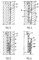
- la figure 6 représente partiellement en coupe une variante de piston selon l'invention ;
- la figure 7 représente en coupe une autre variante de piston selon l'invention.
- Figure 1 is a partial sectional view of a dispensing assembly according to the invention;
- Figure 2 is a sectional view of a piston of the prior art;
- Figures 3 to 5 schematically show the molding operations leading to the piston according to the invention;
- Figure 6 partially shows in section a variant of piston according to the invention;
- Figure 7 shows in section another variant of piston according to the invention.
L'ensemble de distribution 1 représenté sur la figure 1 comprend un récipient 2 rigide en matériau thermoplastique extrudé ou injecté à paroi latérale cylindrique 3 ; le récipient 2 comprend, à l'intérieur de la paroi 3, un piston suiveur 16 dont la face opposée au produit contenu dans le récipient 2 est soumise à la pression atmosphérique grâce à l'existence d'un trou 4 prévu dans le fond 5 du récipient 2 ; un ressort pourrait être disposé entre le fond 5 et le piston 16.The distribution assembly 1 shown in FIG. 1 comprises a rigid container 2 made of extruded or injected thermoplastic material with a cylindrical side wall 3; the container 2 comprises, inside the wall 3, a
Une embase 6 en forme de cuvette est encliquetée à l'extrémité supérieure du récipient 2 à l'aide de bourrelets 7 reçus par des gorges conjuguées prévues sur la surface intérieure de la paroi 3 ; une collerette 8 portée par l'embase 6 vient coiffer l'extrémité supérieure de la paroi 3 avec serrage d'une rondelle d'étanchéité 9.A
Un organe de distribution, par exemple une pompe de distribution 12 sans reprise d'air, est supporté de façon étanche par une coupelle 14 sertie à la partie supérieure d'un manchon dans lequel elle s'étend ; le manchon est claqué, également de façon étanche, sur un fourreau 11 porté par le fond de l'embase 6, dans la concavité de ladite embase 6 ; la tige 13 de distribution de la pompe 12 supporte un organe de manoeuvre 15 en forme de bouton-poussoir ; un tel ensemble de distribution est bien connu en soi et ne sera pas décrit plus en détail.A distribution member, for example a
La figure 2 représente un piston 50 équipant habituellement un ensemble de distribution du genre de celui décrit à propos de la figure 1 ; le piston 50 comprend un corps 56 en matière plastique moulée rigide, de section circulaire, présentant à la périphérie une lèvre 57 venue de moulage et située axialement au voisinage d'une gorge dans laquelle est placé un joint torique 58 ; un tel piston 50 présente des inconvénients : d'une part, des fuites peuvent se produire entre le joint et la paroi interne du récipient, et/ou entre le joint et le piston du fait que, monté roulant dans la gorge du piston, le joint n'est pas monté serré de façon identique sur toute la périphérie de la gorge ; d'autre part, la technologie de moulage conduit à la présence, à la surface du joint torique, d'une micro-bavure correspondant au plan de joint des deux machoires du moule, cette micro-bavure étant située dans le plan du plus grand diamètre du tore, ou dans un plan voisin de celui-ci : cette micro-bavure est à l'origine de certaines fuites lorsqu'elle se trouve être en contact avec la paroi interne du récipient, et que le joint n'est pas monté serré. Un tel piston 50 est en outre onéreux car non seulement la fabrication du corps du piston nécessite un moule à tiroir, l'obtention de la gorge destinée à recevoir le joint torique ne pouvant pas être obtenue autrement, mais également l'opération de montage du joint torique dans ladite gorge n'est pas gratuite, même en automatique.2 shows a
Le piston 16, conformément à la présente invention, ne présente pas ces inconvénients.The
Le corps 10 du piston 16 est constitué d'un matériau thermoplastique rigide et le joint 17 d'un matériau flexible, comme un thermoplastique ou un élastomère dont la sureté Shore A est de l'ordre de 30 à 120, inférieure à celle du corps 10 ; le corps 10 du piston 16 est de forme concave et sa concavité est dirigée vers le fond 5 du récipient 2 lorsqu'il est monté dans celui-ci ; le corps 10 présente sur au moins une partie de sa longueur, correspondant à une portion cylindrique inférieure 24, un diamètre extérieur égal, au jeu de montage près, au diamètre intérieur de la paroi 3 du récipient 2.The
Le joint 17 placé au droit d'une portion cylindrique 25 du corps 10 de diamètre légèrement inférieur à celui de la portion 24, présente une lèvre 19 et une portion semi-torique 18 située au voisinage de la lèvre 19 ; le joint 17 est obtenu en surmoulant partiellement le corps 10, in situ, dans un deuxième temps, après l'opération de moulage proprement dite du corps 10 ; les figures 3 à 5 montrent schématiquement ces diverses opérations : sur la figure 3, les deux machoires 20 et 21, à empreintes, du moule de la machine de moulage sont fermées et prêtes à recevoir le matériau rigide 30 pour réaliser le corps 10 du piston 16, et, dans un premier temps, le corps 10 est moulé ; dans un deuxième temps, comme montré sur la figure 4, les machoires 20 et 21 sont écartées l'une de l'autre, selon un jeu 22, libérant ainsi un volume 23 dans lequel est injecté le matériau élastique 31, comme cela est visible sur la figure 5, pour réaliser le joint 17 dont la lèvre 19 et la portion semi-torique 18 sont ainsi réalisées en même temps et d'une seule pièce. On aura noté que cette opération de surmoulage a permis non seulement la réalisation du joint 17 mais également son montage sur le corps 10 du piston 16 sur lequel il est maintenu en raison du fait que les matériaux 30 et 31 ont été prévus chimiquement compatibles pour assurer une cohésion entre les deux matériaux obtenue par la formation, lors du moulage, de liaisons d'adhésion par mélange des matériaux à l'interface. On peut prendre comme couples de matériaux rigide et élastique des couples composés, par exemple de polyoléfine, polyester, polystyrène ou polyamide, pour le corps 10 du piston 16 et d'un mélange de polyoléfines ou d'autres polyoléfines pour le joint 17 : ces couples peuvent être, par exemple polypropylène-EPDM, polypropylène-polyéthylène, polypropylène-styréniques, polypropylène-copolymère EPDM/polypropylène, nylon-polyéthylène...The
Les produits couramment utilisés, dans ce type d'ensemble de distribution, ont une viscosité de 10 à 50 poises ; il peut s'agir d'une émulsion d'huile dans l'eau (ou d'eau dans l'huile), dont la viscosité est de l'ordre de 12 poises, d'un gel, dont la viscosité est de l'ordre de 50 poises, d'un liquide épaissi, dont la viscosité est de l'ordre de 30 poises, voir des produits de viscosité supérieure à 50 poises, pouvant par exemple aller jusqu'à 70 poises ; la présente invention permet de distribuer, avec un tel type d'ensemble de distribution, un produit de viscosité encore plus faible, pouvant même descendre au dessous de 1 poise : il suffit, si nécessaire, de prévoir un joint ayant deux ou plusieurs portions semi-toriques, ce qui est réalisable facilement et à moindre coût grâce à l'invention ; la figure 6 représente un tel joint 27 solidaire du corps 26 du piston, le joint 27 comportant, outre la lèvre 29, deux portions 28A, 28B semi-toriques.The products commonly used in this type of dispensing assembly have a viscosity of 10 to 50 poises; it can be an oil in water emulsion (or water in oil), whose viscosity is of the order of 12 poises, a gel, whose viscosity is l 'order of 50 poises, of a thickened liquid, the viscosity of which is of the order of 30 poises, see products of viscosity greater than 50 poises, being able for example to go up to 70 poises; the present invention makes it possible to distribute, with such a type of distribution assembly, a product of even lower viscosity, which can even drop below 1 poise: it suffices, if necessary, to provide a seal having two or more semi portions toric, which is easily achievable and inexpensive thanks to the invention; FIG. 6 shows such a
Des produits variés peuvent être distribués : gels automoussants, par exemple gels à raser, produits dépilatoires, crèmes de soin, produits de soin capillaire, de coloration... Le récipient 2 a été décrit en matériau thermoplastique extrudé ou injecté ; en variante, il est en alu monobloc, et le piston y a été introduit avant conformation du col pour fixation de l'organe de distribution.Various products can be distributed: self-foaming gels, for example shaving gels, depilatory products, care creams, hair care products, coloring products ... The container 2 has been described in extruded or injected thermoplastic material; as a variant, it is made of a single piece of aluminum, and the piston has been introduced there before the neck is shaped for fixing the dispensing member.
L'organe de distribution de l'ensemble de distribution décrit à propos de la figure 1 comporte une pompe de distribution ; bien entendu, l'organe de distribution pourrait être une valve de distribution et le piston poussé par un propulseur gazeux sous pression prévu dans le volume compris entre le fond du récipient et le piston, auquel cas, le fond du récipient est muni d'un clapet antiretour de remplissage en propulseur gazeux ou de tout autre système de remplissage connu ; l'organe de distribution pourrait également être constitué par le piston lui-même sur lequel on agirait directement manuellement, l'ensemble de distribution étant dès lors constitué par une seringue.The distribution member of the distribution assembly described in connection with FIG. 1 comprises a distribution pump; of course, the dispensing member could be a dispensing valve and the piston pushed by a pressurized gas propellant provided in the volume between the bottom of the container and the piston, in which case, the bottom of the container is provided with a non-return valve for filling with a gas propellant or any other known filling system; the dispensing member could also be constituted by the piston itself on which one would act directly manually, the dispensing assembly therefore being constituted by a syringe.
Le procédé de réalisation du piston selon l'invention décrit à propos de la variante de piston 16 selon la figure 1 est applicable à la réalisation de la variante de piston 46 représentée sur la figure 7 ; le piston 46 comprend un corps 40 constitué d'un matériau relativement rigide et un joint 47 constitué d'un matériau flexible obtenu en surmoulant partiellement le corps 40 in situ ; plus précisément, selon cette variante de la figure 7, le corps 40 du piston creux 46 présente successivement trois portions cylindriques 41, 42, 44 de diamètres successivement croissants, la portion 44 se terminant par un bord 45 de forme tronconique ; à partir de la jonction entre les portions 42 et 44, s'étend une lèvre 49 dont la section décroit jusqu'à son extrémité libre et qui entoure partiellement la portion 42 ; la lèvre 49 est venue de moulage en même temps que le corps 40 du piston 46 et est analogue à la lèvre 57 décrite à propos du piston 50 de la figure 2 ; le joint 47 a une section, par un plan passant par l'axe longitudinal du piston 46, de forme générale en parallélogramme, comme visible sur la figure 7, et présente une portion 48 semi-torique ; le joint 47 est assujetti au corps 40 par surmoulage in situ de son rebord 45. Un tel piston 46, de réalisation simple, présente les mêmes avantages que ceux décrits à propos du piston 16 de la figure 1. Le piston 46 est de préférence utilisé dans un ensemble de distribution dont l'organe de distribution est une valve de distribution et le piston poussé par un propulseur gazeux sous pression, laquelle pression plaque avantageusement le joint 47, placé à l'extrémité ouverte du piston 46, contre la paroi intérieure du récipient 2 ; mais d'excellents résultats ont également été obtenus en utilisant le piston 46 dans un ensemble de distribution dont l'organe de distribution est une pompe de distribution, comme décrit à propos de la figure 1 ; avantageusement, le corps 40 du piston 46 est en polypropylène et le joint 47 est en copolymère EPDM/polypropylène.The method of producing the piston according to the invention described with regard to the variant of
Claims (11)
- Dispensing assembly comprising a container (2) and a dispensing member for dispensing the product contained in the container (2), the container (2) being cylindrical and including a piston (16, 26, 46) consisting of a body (10, 40) made of rigid material (30) having a cylindrical part carrying a seal (17, 27, 47) made of elastic material (31), characterized in that the seal (17, 27, 47) is obtained by overmoulding the body (10, 40) of the piston (16, 26, 46) made of rigid material (30), the elastic material (31) and the rigid material (30) being chemically compatible in order to ensure that the seal (17, 27, 47) and the body (10, 40) of the piston (16, 26, 46) are bonded together, the seal (17, 27, 47) having at least one semi-toric portion (18, 48) and a sealing lip (19, 29).
- Dispensing assembly according to Claim 1, characterized in that the seal (27) has at least two semi-toric portions (28A, 28B).
- Dispensing assembly according to either of Claims 1 and 2, characterized in that the seal (17, 27) is placed right at an intermediate portion (25) of the body (10) of the piston (16, 26).
- Dispensing assembly according to either of Claims 1 and 2, characterized in that the seal (47) is placed right at the edge (45) of the open end of the body (40) of the piston (46).
- Dispensing assembly according to one of Claims 1 to 4, characterized in that the seal (17, 27, 47) made of elastic material (31) has a Shore A hardness of between 30 and 120.
- Dispensing assembly according to one of Claims 1 to 5, characterized in that the pair of rigid (30) and elastic (31) materials is a pair of thermoplastic materials which is chosen from the group formed by the pairs polypropylene-EPDM, polypropylene-polyethylene, polypropylene-styrenics, polypropylene-EPDM/polypropylene copolymer, polyamide-polyethylene, polyester-EPDM, polystyrene-polyethylene.
- Dispensing assembly according to one of Claims 1 to 6, characterized in that the product to be dispensed has a viscosity of between an approximate value of 1 poise and an approximate value of 70 poise.
- Dispensing assembly according to one of Claims 1 to 7, characterized in that the dispensing member is a pump (12) having no air uptake, the bottom (5) of the container (2) including an orifice (4).
- Dispensing assembly according to one of Claims 1 to 7, characterized in that the dispensing member is a dispensing valve, the piston (16, 26, 46) being pushed by a gaseous propellant under pressure, the said propellant being provided in the volume lying between the bottom of the container (2) and the piston (16, 26, 46).
- Dispensing assembly according to Claim 9, characterized in that the bottom of the container is equipped with a filling system for filling with gaseous propellant.
- Dispensing assembly according to one of Claims 1 to 7, characterized in that the dispensing member is the piston (16, 26, 46) itself, which can be manually actuated, the dispensing assembly (1) constituting a syringe.
Applications Claiming Priority (3)
| Application Number | Priority Date | Filing Date | Title |
|---|---|---|---|
| FR9306704 | 1993-06-04 | ||
| FR9306704A FR2705951B1 (en) | 1993-06-04 | 1993-06-04 | Distribution assembly comprising a cylindrical container comprising a piston. |
| PCT/FR1994/000639 WO1994029190A1 (en) | 1993-06-04 | 1994-06-01 | Dispensing unit comprising a cylindrical container enclosing a piston |
Publications (2)
| Publication Number | Publication Date |
|---|---|
| EP0652842A1 EP0652842A1 (en) | 1995-05-17 |
| EP0652842B1 true EP0652842B1 (en) | 1997-03-05 |
Family
ID=9447766
Family Applications (1)
| Application Number | Title | Priority Date | Filing Date |
|---|---|---|---|
| EP94917700A Expired - Lifetime EP0652842B1 (en) | 1993-06-04 | 1994-06-01 | Dispensing unit comprising a cylindrical container enclosing a piston |
Country Status (6)
| Country | Link |
|---|---|
| US (1) | US5577641A (en) |
| EP (1) | EP0652842B1 (en) |
| DE (1) | DE69401895T2 (en) |
| ES (1) | ES2099614T3 (en) |
| FR (1) | FR2705951B1 (en) |
| WO (1) | WO1994029190A1 (en) |
Families Citing this family (29)
| Publication number | Priority date | Publication date | Assignee | Title |
|---|---|---|---|---|
| DE4422842C1 (en) * | 1994-06-30 | 1995-08-17 | Sidler Gmbh & Co | Sealed housing useful for shrouding for powered rotating components |
| GB9513084D0 (en) * | 1995-06-27 | 1995-08-30 | Bespak Plc | Dispensing apparatus |
| CA2202944A1 (en) * | 1996-05-06 | 1997-11-06 | Douglas M. Mclelland | Closure plug with bonded gasket |
| US5779107A (en) * | 1997-01-24 | 1998-07-14 | Clayton Corporation | Pressurizable container assembly and piston member therefor |
| EP0867403A1 (en) * | 1997-03-24 | 1998-09-30 | Sicpa Holding S.A. | Scraping element, piston and arrangement for emptying a bag-like envelope containing a pasty liquid |
| FR2780123B1 (en) * | 1998-06-19 | 2003-05-23 | Valeo | HYDRAULICALLY CONTROLLED RELEASE DEVICE |
| FR2780122B1 (en) * | 1998-06-19 | 2000-12-29 | Valeo | HYDRAULICALLY CONTROLLED RELEASE DEVICE |
| FR2781210B3 (en) * | 1998-07-17 | 2000-08-18 | Cebal | DISPENSER OF CREAMY PRODUCTS UNDER PRESSURE PROVIDED WITH A SEALED PISTON |
| FR2781209B1 (en) * | 1998-07-17 | 2000-08-25 | Cebal | DISPENSER OF CREAMY PRODUCTS UNDER PRESSURE PROVIDED WITH A SEALED PISTON |
| DE19915022B4 (en) * | 1999-04-01 | 2007-01-18 | Dichtungstechnik G. Bruss Gmbh & Co. Kg | Elastomeric seal between a piston and a cylinder and / or a shaft of an automatic motor vehicle transmission |
| US6244475B1 (en) * | 1999-06-21 | 2001-06-12 | David K. Walz | Hair treatment dispensing container |
| US6490964B2 (en) * | 2000-01-24 | 2002-12-10 | Delphi Technologies, Inc. | Master brake cylinders having overmolded seals |
| DE602005023625D1 (en) * | 2004-07-30 | 2010-10-28 | Gl Tool And Mfg Co Inc | VALVE |
| US8091864B2 (en) * | 2005-12-20 | 2012-01-10 | Ds Smith Plastics Limited | Valve for a fluid flow connector having an overmolded plunger |
| US7891528B2 (en) * | 2006-07-03 | 2011-02-22 | Nordson Corporation | Dispenser and piston for dispensing a liquid material |
| US8245888B2 (en) * | 2008-10-24 | 2012-08-21 | S.C. Johnson & Son, Inc. | Barrier piston with seal |
| US8561762B2 (en) * | 2009-09-03 | 2013-10-22 | Honda Motor Co., Ltd. | Brake piston with steel core and phenolic outer layer |
| FR2956098B1 (en) * | 2010-02-11 | 2012-03-30 | Airlessystems | FLUID PRODUCT DISPENSER. |
| JP5690548B2 (en) * | 2010-10-14 | 2015-03-25 | リューベ株式会社 | Lubricant cartridge container |
| US20150109380A1 (en) * | 2010-12-27 | 2015-04-23 | North America Wales Group International Ltd. | Vacuum piston device |
| FR3005890B1 (en) * | 2013-05-24 | 2015-10-16 | Georges David Ets | METHOD FOR MOLDING TWO-COLOR FLOWER POTS AND POT MADE THEREBY |
| US9798275B2 (en) * | 2014-06-05 | 2017-10-24 | Clover Technologies Group, Llc | System and method for applying lubricant onto a surface |
| FR3052446B1 (en) * | 2016-06-10 | 2018-07-13 | Karine Courtin | DEVICE FOR DISPENSING FLUID PRODUCT |
| ES2887000T3 (en) * | 2016-11-28 | 2021-12-21 | Oreal | Device for packaging and dispensing a product comprising a mobile piston |
| IT201700056483A1 (en) * | 2017-05-24 | 2018-11-24 | Lumson Spa | Container of fluid substances with mobile bottom, with hermetic closure system and method of use |
| EP3489171A1 (en) * | 2017-11-23 | 2019-05-29 | The Procter & Gamble Company | Piston with flexible closure for aerosol container |
| EP3513880B1 (en) | 2018-01-23 | 2021-08-25 | The Procter & Gamble Company | Dispensing device suitable for a foamable product |
| US10850914B2 (en) | 2018-11-08 | 2020-12-01 | The Procter And Gamble Company | Dip tube aerosol dispenser with upright actuator |
| US11267644B2 (en) | 2018-11-08 | 2022-03-08 | The Procter And Gamble Company | Aerosol foam dispenser and methods for delivering a textured foam product |
Family Cites Families (18)
| Publication number | Priority date | Publication date | Assignee | Title |
|---|---|---|---|---|
| US2310917A (en) * | 1940-07-10 | 1943-02-16 | Daly Le Grand | Self-packing piston |
| US2777741A (en) * | 1953-06-22 | 1957-01-15 | Bosch Gmbh Robert | Device for providing a slidable seal between a piston and cylinder |
| US2815994A (en) * | 1955-03-07 | 1957-12-10 | Aaron H Lippman | Self-adjusting piston for soap dispenser |
| FR1200293A (en) * | 1958-03-27 | 1959-12-21 | Dosing dispenser | |
| US3052194A (en) * | 1961-09-22 | 1962-09-04 | Chace D Gilmore | Cutter disks for reciprocating doughnut formers |
| US3282469A (en) * | 1965-04-16 | 1966-11-01 | Albert W Skonberg | Heated dispensing apparatus |
| FR2045559B2 (en) * | 1968-12-10 | 1975-08-22 | Oreal | |
| US4027810A (en) * | 1976-01-27 | 1977-06-07 | Voplex Corporation | Sealing plunger for cartridge |
| AU3950678A (en) * | 1977-10-11 | 1980-03-13 | Population Res Inc | Ampule |
| DE3148490C2 (en) * | 1981-12-08 | 1986-02-13 | Alfred Fischbach Kg Kunststoff-Spritzgusswerk, 5250 Engelskirchen | Bottom closure for a hollow cylindrical extrusion container |
| HU189198B (en) * | 1982-12-10 | 1986-06-30 | Adorjan,Andras,Hu | Plastic syringe for single use as well as plastic piston particularly for plastic syringes |
| DE3405547A1 (en) * | 1984-02-16 | 1985-08-14 | Hilti Ag, Schaan | PRESSING PISTON FOR CONTAINERS |
| GB2192577B (en) * | 1986-07-18 | 1990-01-10 | Wavin Bv | Channel conduit couplings |
| US4703875A (en) * | 1986-07-24 | 1987-11-03 | S. C. Johnson & Son, Inc. | Low mass piston for aerosol container |
| DE3731158A1 (en) * | 1987-09-17 | 1989-03-30 | Festo Kg | PISTON CYLINDER AGGREGATE |
| US4907727A (en) * | 1988-10-31 | 1990-03-13 | Illinois Tool Works, Inc. | Dispensing device having improved plunger assemblies |
| CA2027786C (en) * | 1989-10-31 | 1997-01-28 | Koichi Sugita | Combination container and pump |
| FR2671540B1 (en) * | 1991-01-16 | 1994-09-16 | Cebal | SLIDING PISTON FOR DISTRIBUTOR. |
-
1993
- 1993-06-04 FR FR9306704A patent/FR2705951B1/en not_active Expired - Fee Related
-
1994
- 1994-06-01 DE DE69401895T patent/DE69401895T2/en not_active Expired - Fee Related
- 1994-06-01 US US08/374,718 patent/US5577641A/en not_active Expired - Fee Related
- 1994-06-01 EP EP94917700A patent/EP0652842B1/en not_active Expired - Lifetime
- 1994-06-01 ES ES94917700T patent/ES2099614T3/en not_active Expired - Lifetime
- 1994-06-01 WO PCT/FR1994/000639 patent/WO1994029190A1/en active IP Right Grant
Also Published As
| Publication number | Publication date |
|---|---|
| WO1994029190A1 (en) | 1994-12-22 |
| FR2705951B1 (en) | 1995-08-11 |
| DE69401895T2 (en) | 1997-10-09 |
| EP0652842A1 (en) | 1995-05-17 |
| US5577641A (en) | 1996-11-26 |
| DE69401895D1 (en) | 1997-04-10 |
| ES2099614T3 (en) | 1997-05-16 |
| FR2705951A1 (en) | 1994-12-09 |
Similar Documents
| Publication | Publication Date | Title |
|---|---|---|
| EP0652842B1 (en) | Dispensing unit comprising a cylindrical container enclosing a piston | |
| EP0899213B1 (en) | Pump-type packaging unit for a liquid or semi-liquid product | |
| EP1671705B1 (en) | Plastic dispenser with a pump | |
| EP0549050B1 (en) | Assembly for dispensing at least one fluid product such as cosmetics or pharmaceutics | |
| EP1193186B1 (en) | Device for the reversible fixation of a container on a support and container equipped with such a device | |
| EP1814672B1 (en) | Flexible part forming an output valve and a return spring for a dispensing device | |
| EP0628355B1 (en) | Dispenser head, particularly for pasty products, and dispenser equipped therewith | |
| FR2776628A1 (en) | PACKAGING AND DISPENSING ASSEMBLY OF A LIQUID PRODUCT | |
| EP0905052B1 (en) | Storage and dispensing device for a liquid or semi-liquid product | |
| EP1171367B1 (en) | Fixing element for dispensing a liquid product and dispenser comprising said element | |
| EP0939039A1 (en) | Dispensing head for the dispensing of a material and assembly for dispensing under pressure equipped with such a head | |
| EP0821775B1 (en) | Inlet valve assembly | |
| EP1472007B1 (en) | Pump liquid product dispenser | |
| EP1004523B1 (en) | Dispensing valve for pressurised fluid | |
| EP0850851B1 (en) | Dispensing valve for pressurised fluids | |
| FR2779205A1 (en) | VALVE AND PACKAGING AND DISTRIBUTION ASSEMBLY PROVIDED WITH SUCH A VALVE | |
| FR2791328A1 (en) | PISTON TYPE PACKAGING AND PRESSURIZED DISTRIBUTION ASSEMBLY AND METHOD FOR MOUNTING SUCH AN ASSEMBLY | |
| EP0385896A1 (en) | Dispenser body, dispenser having such a body and cap therefor | |
| EP2308604B1 (en) | Dispensing system for a fluid product | |
| EP3256261B1 (en) | Mounting arragnement for a dispenser | |
| FR2708314A1 (en) | Improvements to metering pumps | |
| FR2516899A1 (en) | DEVICE FOR REMOVING PASTE SUBSTANCES IN CONTAINERS FILLED WITH PROPELLER GAS | |
| FR2772010A1 (en) | Fluid product container dispensing head | |
| FR2753178A1 (en) | Reception dish for paste dispenser | |
| EP1499449A1 (en) | Fluid product dispensing pump |
Legal Events
| Date | Code | Title | Description |
|---|---|---|---|
| PUAI | Public reference made under article 153(3) epc to a published international application that has entered the european phase |
Free format text: ORIGINAL CODE: 0009012 |
|
| 17P | Request for examination filed |
Effective date: 19950124 |
|
| AK | Designated contracting states |
Kind code of ref document: A1 Designated state(s): DE ES FR GB IT |
|
| 17Q | First examination report despatched |
Effective date: 19960423 |
|
| GRAG | Despatch of communication of intention to grant |
Free format text: ORIGINAL CODE: EPIDOS AGRA |
|
| GRAH | Despatch of communication of intention to grant a patent |
Free format text: ORIGINAL CODE: EPIDOS IGRA |
|
| GRAH | Despatch of communication of intention to grant a patent |
Free format text: ORIGINAL CODE: EPIDOS IGRA |
|
| GRAA | (expected) grant |
Free format text: ORIGINAL CODE: 0009210 |
|
| AK | Designated contracting states |
Kind code of ref document: B1 Designated state(s): DE ES FR GB IT |
|
| ITF | It: translation for a ep patent filed |
Owner name: 0403;05TOFJACOBACCI & PERANI S.P.A. |
|
| GBT | Gb: translation of ep patent filed (gb section 77(6)(a)/1977) |
Effective date: 19970305 |
|
| REF | Corresponds to: |
Ref document number: 69401895 Country of ref document: DE Date of ref document: 19970410 |
|
| REG | Reference to a national code |
Ref country code: ES Ref legal event code: FG2A Ref document number: 2099614 Country of ref document: ES Kind code of ref document: T3 |
|
| PLBE | No opposition filed within time limit |
Free format text: ORIGINAL CODE: 0009261 |
|
| STAA | Information on the status of an ep patent application or granted ep patent |
Free format text: STATUS: NO OPPOSITION FILED WITHIN TIME LIMIT |
|
| 26N | No opposition filed | ||
| PGFP | Annual fee paid to national office [announced via postgrant information from national office to epo] |
Ref country code: DE Payment date: 20000529 Year of fee payment: 7 |
|
| PGFP | Annual fee paid to national office [announced via postgrant information from national office to epo] |
Ref country code: GB Payment date: 20000531 Year of fee payment: 7 |
|
| PGFP | Annual fee paid to national office [announced via postgrant information from national office to epo] |
Ref country code: FR Payment date: 20000612 Year of fee payment: 7 |
|
| PGFP | Annual fee paid to national office [announced via postgrant information from national office to epo] |
Ref country code: ES Payment date: 20000623 Year of fee payment: 7 |
|
| PG25 | Lapsed in a contracting state [announced via postgrant information from national office to epo] |
Ref country code: GB Free format text: LAPSE BECAUSE OF NON-PAYMENT OF DUE FEES Effective date: 20010601 |
|
| PG25 | Lapsed in a contracting state [announced via postgrant information from national office to epo] |
Ref country code: ES Free format text: LAPSE BECAUSE OF NON-PAYMENT OF DUE FEES Effective date: 20010602 |
|
| GBPC | Gb: european patent ceased through non-payment of renewal fee |
Effective date: 20010601 |
|
| PG25 | Lapsed in a contracting state [announced via postgrant information from national office to epo] |
Ref country code: FR Free format text: LAPSE BECAUSE OF NON-PAYMENT OF DUE FEES Effective date: 20020228 |
|
| PG25 | Lapsed in a contracting state [announced via postgrant information from national office to epo] |
Ref country code: DE Free format text: LAPSE BECAUSE OF NON-PAYMENT OF DUE FEES Effective date: 20020403 |
|
| REG | Reference to a national code |
Ref country code: ES Ref legal event code: FD2A Effective date: 20030203 |
|
| PG25 | Lapsed in a contracting state [announced via postgrant information from national office to epo] |
Ref country code: IT Free format text: LAPSE BECAUSE OF NON-PAYMENT OF DUE FEES;WARNING: LAPSES OF ITALIAN PATENTS WITH EFFECTIVE DATE BEFORE 2007 MAY HAVE OCCURRED AT ANY TIME BEFORE 2007. THE CORRECT EFFECTIVE DATE MAY BE DIFFERENT FROM THE ONE RECORDED. Effective date: 20050601 |