EP0652842B1 - Abgabevorrichtung mit einem zylindrischen behälter und einem kolben - Google Patents
Abgabevorrichtung mit einem zylindrischen behälter und einem kolben Download PDFInfo
- Publication number
- EP0652842B1 EP0652842B1 EP94917700A EP94917700A EP0652842B1 EP 0652842 B1 EP0652842 B1 EP 0652842B1 EP 94917700 A EP94917700 A EP 94917700A EP 94917700 A EP94917700 A EP 94917700A EP 0652842 B1 EP0652842 B1 EP 0652842B1
- Authority
- EP
- European Patent Office
- Prior art keywords
- piston
- seal
- dispensing
- container
- dispensing assembly
- Prior art date
- Legal status (The legal status is an assumption and is not a legal conclusion. Google has not performed a legal analysis and makes no representation as to the accuracy of the status listed.)
- Expired - Lifetime
Links
- 239000000463 material Substances 0.000 claims abstract description 19
- 229920002943 EPDM rubber Polymers 0.000 claims description 10
- 239000013013 elastic material Substances 0.000 claims description 10
- 239000003380 propellant Substances 0.000 claims description 9
- 239000004698 Polyethylene Substances 0.000 claims description 8
- 229920000573 polyethylene Polymers 0.000 claims description 8
- 238000007789 sealing Methods 0.000 claims description 6
- 239000012815 thermoplastic material Substances 0.000 claims description 5
- 229920005606 polypropylene copolymer Polymers 0.000 claims description 3
- 239000012858 resilient material Substances 0.000 abstract 2
- 238000009826 distribution Methods 0.000 description 18
- 238000000465 moulding Methods 0.000 description 9
- 239000003570 air Substances 0.000 description 5
- 238000011065 in-situ storage Methods 0.000 description 5
- -1 polypropylene Polymers 0.000 description 4
- 239000000499 gel Substances 0.000 description 3
- 238000004519 manufacturing process Methods 0.000 description 3
- 239000002991 molded plastic Substances 0.000 description 3
- 229920000098 polyolefin Polymers 0.000 description 3
- 239000004743 Polypropylene Substances 0.000 description 2
- 238000010276 construction Methods 0.000 description 2
- 238000005304 joining Methods 0.000 description 2
- 229920001155 polypropylene Polymers 0.000 description 2
- 239000004952 Polyamide Substances 0.000 description 1
- 239000004793 Polystyrene Substances 0.000 description 1
- XAGFODPZIPBFFR-UHFFFAOYSA-N aluminium Chemical compound [Al] XAGFODPZIPBFFR-UHFFFAOYSA-N 0.000 description 1
- 229910052782 aluminium Inorganic materials 0.000 description 1
- 239000012080 ambient air Substances 0.000 description 1
- 238000004873 anchoring Methods 0.000 description 1
- 239000011324 bead Substances 0.000 description 1
- 230000015572 biosynthetic process Effects 0.000 description 1
- 238000004040 coloring Methods 0.000 description 1
- 150000001875 compounds Chemical class 0.000 description 1
- 230000008602 contraction Effects 0.000 description 1
- 229920001577 copolymer Polymers 0.000 description 1
- 239000006071 cream Substances 0.000 description 1
- 230000007423 decrease Effects 0.000 description 1
- 230000002951 depilatory effect Effects 0.000 description 1
- 229920001971 elastomer Polymers 0.000 description 1
- 239000000806 elastomer Substances 0.000 description 1
- 238000005516 engineering process Methods 0.000 description 1
- 238000005187 foaming Methods 0.000 description 1
- 239000000118 hair dye Substances 0.000 description 1
- 238000002347 injection Methods 0.000 description 1
- 239000007924 injection Substances 0.000 description 1
- 239000007788 liquid Substances 0.000 description 1
- 238000000034 method Methods 0.000 description 1
- 239000000203 mixture Substances 0.000 description 1
- 239000007764 o/w emulsion Substances 0.000 description 1
- 229920002647 polyamide Polymers 0.000 description 1
- 229920000728 polyester Polymers 0.000 description 1
- 229920002223 polystyrene Polymers 0.000 description 1
- 238000005096 rolling process Methods 0.000 description 1
- 230000003068 static effect Effects 0.000 description 1
- 238000003860 storage Methods 0.000 description 1
- 239000000126 substance Substances 0.000 description 1
- 229920001169 thermoplastic Polymers 0.000 description 1
- 239000004416 thermosoftening plastic Substances 0.000 description 1
- XLYOFNOQVPJJNP-UHFFFAOYSA-N water Substances O XLYOFNOQVPJJNP-UHFFFAOYSA-N 0.000 description 1
Images

Classifications
-
- B—PERFORMING OPERATIONS; TRANSPORTING
- B65—CONVEYING; PACKING; STORING; HANDLING THIN OR FILAMENTARY MATERIAL
- B65D—CONTAINERS FOR STORAGE OR TRANSPORT OF ARTICLES OR MATERIALS, e.g. BAGS, BARRELS, BOTTLES, BOXES, CANS, CARTONS, CRATES, DRUMS, JARS, TANKS, HOPPERS, FORWARDING CONTAINERS; ACCESSORIES, CLOSURES, OR FITTINGS THEREFOR; PACKAGING ELEMENTS; PACKAGES
- B65D83/00—Containers or packages with special means for dispensing contents
- B65D83/14—Containers or packages with special means for dispensing contents for delivery of liquid or semi-liquid contents by internal gaseous pressure, i.e. aerosol containers comprising propellant for a product delivered by a propellant
- B65D83/60—Contents and propellant separated
- B65D83/64—Contents and propellant separated by piston
-
- B—PERFORMING OPERATIONS; TRANSPORTING
- B05—SPRAYING OR ATOMISING IN GENERAL; APPLYING FLUENT MATERIALS TO SURFACES, IN GENERAL
- B05B—SPRAYING APPARATUS; ATOMISING APPARATUS; NOZZLES
- B05B11/00—Single-unit hand-held apparatus in which flow of contents is produced by the muscular force of the operator at the moment of use
- B05B11/01—Single-unit hand-held apparatus in which flow of contents is produced by the muscular force of the operator at the moment of use characterised by the means producing the flow
- B05B11/02—Membranes or pistons acting on the contents inside the container, e.g. follower pistons
- B05B11/028—Pistons separating the content remaining in the container from the atmospheric air to compensate underpressure inside the container
-
- B—PERFORMING OPERATIONS; TRANSPORTING
- B29—WORKING OF PLASTICS; WORKING OF SUBSTANCES IN A PLASTIC STATE IN GENERAL
- B29C—SHAPING OR JOINING OF PLASTICS; SHAPING OF MATERIAL IN A PLASTIC STATE, NOT OTHERWISE PROVIDED FOR; AFTER-TREATMENT OF THE SHAPED PRODUCTS, e.g. REPAIRING
- B29C45/00—Injection moulding, i.e. forcing the required volume of moulding material through a nozzle into a closed mould; Apparatus therefor
- B29C45/16—Making multilayered or multicoloured articles
- B29C45/1676—Making multilayered or multicoloured articles using a soft material and a rigid material, e.g. making articles with a sealing part
-
- B—PERFORMING OPERATIONS; TRANSPORTING
- B65—CONVEYING; PACKING; STORING; HANDLING THIN OR FILAMENTARY MATERIAL
- B65D—CONTAINERS FOR STORAGE OR TRANSPORT OF ARTICLES OR MATERIALS, e.g. BAGS, BARRELS, BOTTLES, BOXES, CANS, CARTONS, CRATES, DRUMS, JARS, TANKS, HOPPERS, FORWARDING CONTAINERS; ACCESSORIES, CLOSURES, OR FITTINGS THEREFOR; PACKAGING ELEMENTS; PACKAGES
- B65D83/00—Containers or packages with special means for dispensing contents
- B65D83/0005—Containers or packages provided with a piston or with a movable bottom or partition having approximately the same section as the container
- B65D83/0033—Containers or packages provided with a piston or with a movable bottom or partition having approximately the same section as the container the piston being a follower-piston and the dispensing means comprising a hand-operated pressure-device at the opposite part of the container
-
- B—PERFORMING OPERATIONS; TRANSPORTING
- B29—WORKING OF PLASTICS; WORKING OF SUBSTANCES IN A PLASTIC STATE IN GENERAL
- B29C—SHAPING OR JOINING OF PLASTICS; SHAPING OF MATERIAL IN A PLASTIC STATE, NOT OTHERWISE PROVIDED FOR; AFTER-TREATMENT OF THE SHAPED PRODUCTS, e.g. REPAIRING
- B29C45/00—Injection moulding, i.e. forcing the required volume of moulding material through a nozzle into a closed mould; Apparatus therefor
- B29C45/14—Injection moulding, i.e. forcing the required volume of moulding material through a nozzle into a closed mould; Apparatus therefor incorporating preformed parts or layers, e.g. injection moulding around inserts or for coating articles
- B29C45/14336—Coating a portion of the article, e.g. the edge of the article
- B29C2045/14459—Coating a portion of the article, e.g. the edge of the article injecting seal elements
-
- B—PERFORMING OPERATIONS; TRANSPORTING
- B29—WORKING OF PLASTICS; WORKING OF SUBSTANCES IN A PLASTIC STATE IN GENERAL
- B29C—SHAPING OR JOINING OF PLASTICS; SHAPING OF MATERIAL IN A PLASTIC STATE, NOT OTHERWISE PROVIDED FOR; AFTER-TREATMENT OF THE SHAPED PRODUCTS, e.g. REPAIRING
- B29C45/00—Injection moulding, i.e. forcing the required volume of moulding material through a nozzle into a closed mould; Apparatus therefor
- B29C45/16—Making multilayered or multicoloured articles
- B29C45/1657—Making multilayered or multicoloured articles using means for adhering or bonding the layers or parts to each other
- B29C2045/1664—Chemical bonds
Definitions
- the present invention relates to a dispensing assembly comprising a cylindrical container comprising a piston.
- the present invention relates to a dispensing assembly comprising a container and a dispensing member for dispensing the product contained in the container, the container being cylindrical and comprising a piston made up of a body of rigid material having a cylindrical part bearing a seal made of elastic material.
- the piston comprises a rigid molded plastic body, a part of circular cross section has at the periphery a lip molded with the piston body and located axially in the vicinity of a groove in which is placed an O-ring.
- Such a piston has the drawbacks, on the one hand, of not being a foolproof seal, by construction and in particular in the case where the product to be dispensed is of low viscosity, and, on the other hand, a high cost price, in particular when it is mass produced, these drawbacks being explained in more detail in the description which follows.
- an almost perfect seal is required, in particular in the case where this piston is propelled by a gas under pressure such as compressed air.
- US-A-4,027,810 describes a sealed cartridge plunger for sealing and caulking, the seal is arranged so as to ensure perfect sealing throughout the duration of long storage of the cartridge, the products that it contains being sensitive to air and humidity, and this taking into account the phenomena of thermal contraction and expansion; therefore, the seal is complicated to mold as well as the anchoring means necessary for securing the seal to the body of the plunger, although this seal in use only serves the time to consume the product contained in the cartridge which is then thrown away.
- GB-A-2 192 577 describes a connection for gutter fitted with a seal; the connection and the seal are made of chemically compatible molded plastics making it possible, by in situ molding of the seal on the connection, to secure the seal and avoid having to provide means for retaining the seal during the assembly of the gutter and therefore reduce the cost of assembly; it should be noted that, on the one hand, such a joint is a static joint and that, on the other hand, it is provided in the document to assist, if necessary, the joining of the joint by chemical means of a joining mechanical by molding dovetails for example.
- the present invention is based on the observation made by the inventors that, surprisingly, a movable piston equipped with a seal molded in situ, the piston and the seal being made of chemically compatible materials, gave complete satisfaction from the instant that the seal had at least a semi-toric portion ensuring the tightness and the sliding in both directions of the piston which can thus be used for many product distributions.
- a dispensing assembly comprising a container and a dispensing member for dispensing the product contained in the container, the container being cylindrical and comprising a piston made up of a body of rigid material having a cylindrical part. carrying a seal made of elastic material, is characterized in that the seal is obtained by overmolding of the piston body of rigid material, the elastic material and the rigid material being chemically compatible to ensure the connection of the seal and of the piston body, the seal having at least a semi-toric portion and a sealing lip.
- the seal has at least two semi-toric portions.
- the seal is placed in line with an intermediate portion of the body of the piston, but it could be placed over the entire height of the cylinder; alternatively, the seal is placed in line with the edge of the open end of the piston body.
- the seal made of elastic material has a Shore A hardness of between 30 and 120;
- the pair of rigid and elastic materials is a pair of thermoplastic materials chosen from the group formed by the polypropylene-EPDM, polypropylene-polyethylene, polypropylene-styrenic, polypropylene-EPDM / polypropylene, polyamide-polyethylene, polyester-EPDM, polystyrene-polyethylene pairs.
- EPDM designates a copolymer (ethylene / propylene diene, polymethylene).
- the invention makes it possible to dispense a product having a viscosity between a value close to 1 poise and a value close to 70 poises safely, that is to say without leakage between the piston and the interior wall of the container.
- the dispensing member is a pump without air intake, the bottom of the container comprising an air intake orifice.
- the dispensing member is a dispensing valve, the piston being pushed by a pressurized gas propellant provided in the volume between the bottom of the container and the piston.
- the bottom of the container is provided with a filling system for filling with a gas propellant: for example, the gas propellant is introduced by injection through a plug sealing an orifice located at the bottom of the container.
- the dispensing member is the piston itself, manually actuable, the dispensing assembly constituting a syringe.
- the distribution assembly 1 shown in FIG. 1 comprises a rigid container 2 made of extruded or injected thermoplastic material with a cylindrical side wall 3; the container 2 comprises, inside the wall 3, a follower piston 16 whose face opposite to the product contained in the container 2 is subjected to atmospheric pressure thanks to the existence of a hole 4 provided in the bottom 5 of container 2; a spring could be placed between the bottom 5 and the piston 16.
- a base 6 in the form of a bowl is snapped onto the upper end of the container 2 using beads 7 received by conjugated grooves provided on the inner surface of the wall 3; a flange 8 carried by the base 6 covers the upper end of the wall 3 with tightening of a sealing washer 9.
- a distribution member for example a distribution pump 12 without air intake, is supported in leaktight manner by a cup 14 crimped at the upper part of a sleeve in which it extends; the sleeve is slammed, also in a sealed manner, on a sheath 11 carried by the bottom of the base 6, in the concavity of said base 6; the rod 13 for distributing the pump 12 supports an operating member 15 in the form of a push button; such a distribution assembly is well known per se and will not be described in more detail.
- the piston 50 comprises a body 56 of rigid molded plastic, of circular section, having at the periphery a lip 57 molded and located axially in the vicinity of a groove in which is placed an O-ring 58;
- a piston 50 has drawbacks: on the one hand, leaks can occur between the seal and the internal wall of the container, and / or between the seal and the piston because, mounted rolling in the groove of the piston, the gasket is not tightened identically over the entire periphery of the groove; on the other hand, the molding technology leads to the presence, on the surface of the O-ring, of a micro burr corresponding to the joint plane of the two mold jaws, this micro burr being located in the plane of the largest diameter of the torus, or in a plane close to the latter: this micro-burr is the source of certain leaks when it is found to be in contact with the internal wall of the container, and that the gasket is not mounted tight
- the piston 16, in accordance with the present invention, does not have these drawbacks.
- the body 10 of the piston 16 consists of a rigid thermoplastic material and the seal 17 of a flexible material, such as a thermoplastic or an elastomer whose Shore A safety is of the order of 30 to 120, less than that of the body 10; the body 10 of the piston 16 is of concave shape and its concavity is directed towards the bottom 5 of the container 2 when it is mounted therein; the body 10 has over at least part of its length, corresponding to a lower cylindrical portion 24, an outside diameter equal, apart from the mounting clearance, to the inside diameter of the wall 3 of the container 2.
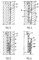
- Figures 3 to 5 schematically show these various operations: in Figure 3, the two jaws 20 and 21, with imprints, of the mold of the molding machine are closed and ready to receive the rigid material 30 to make the body 10 of the piston 16, and, firstly, the body 10 is molded; secondly, as shown in FIG.
- couples of rigid and elastic materials compound couples, for example of polyolefin, polyester, polystyrene or polyamide, for the body 10 of the piston 16 and of a mixture of polyolefins or other polyolefins for the joint 17: these couples can be, for example polypropylene-EPDM, polypropylene-polyethylene, polypropylene-styrenics, polypropylene-EPDM / polypropylene copolymer, nylon-polyethylene ...
- the products commonly used in this type of dispensing assembly have a viscosity of 10 to 50 poises; it can be an oil in water emulsion (or water in oil), whose viscosity is of the order of 12 poises, a gel, whose viscosity is l 'order of 50 poises, of a thickened liquid, the viscosity of which is of the order of 30 poises, see products of viscosity greater than 50 poises, being able for example to go up to 70 poises; the present invention makes it possible to distribute, with such a type of distribution assembly, a product of even lower viscosity, which can even drop below 1 poise: it suffices, if necessary, to provide a seal having two or more semi portions toric, which is easily achievable and inexpensive thanks to the invention; FIG. 6 shows such a seal 27 secured to the body 26 of the piston, the seal 27 comprising, in addition to the lip 29, two semi-toric portions 28A, 28B.
- the container 2 has been described in extruded or injected thermoplastic material; as a variant, it is made of a single piece of aluminum, and the piston has been introduced there before the neck is shaped for fixing the dispensing member.
- the distribution member of the distribution assembly described in connection with FIG. 1 comprises a distribution pump; of course, the dispensing member could be a dispensing valve and the piston pushed by a pressurized gas propellant provided in the volume between the bottom of the container and the piston, in which case, the bottom of the container is provided with a non-return valve for filling with a gas propellant or any other known filling system; the dispensing member could also be constituted by the piston itself on which one would act directly manually, the dispensing assembly therefore being constituted by a syringe.
- the method of producing the piston according to the invention described with regard to the variant of piston 16 according to FIG. 1 is applicable to the production of the variant of piston 46 shown in FIG. 7;
- the piston 46 comprises a body 40 made of a relatively rigid material and a seal 47 made of a flexible material obtained by partially overmolding the body 40 in situ; more specifically, according to this variant of Figure 7, the body 40 of the hollow piston 46 successively has three cylindrical portions 41, 42, 44 of successively increasing diameters, the portion 44 ending in an edge 45 of frustoconical shape; from the junction between the portions 42 and 44, extends a lip 49 whose section decreases to its free end and which partially surrounds the portion 42; the lip 49 has come from molding at the same time as the body 40 of the piston 46 and is similar to the lip 57 described with regard to the piston 50 of FIG.
- the seal 47 has a section, through a plane passing through the longitudinal axis of the piston 46, of general shape in parallelogram, as visible in FIG. 7, and has a semi-toric portion 48; the seal 47 is secured to the body 40 by in situ molding of its rim 45.
- a piston 46 of simple construction, has the same advantages as those described with respect to the piston 16 of FIG. 1.
- the piston 46 is preferably used in a distribution assembly, the distribution member of which is a distribution valve and the piston pushed by a pressurized gas propellant, which pressure advantageously presses the seal 47, placed at the open end of the piston 46, against the internal wall of the container 2; but excellent results have also been obtained by using the piston 46 in a distribution assembly, the distribution member of which is a distribution pump, as described in connection with the figure 1 ; advantageously, the body 40 of the piston 46 is made of polypropylene and the seal 47 is made of EPDM / polypropylene copolymer.
Landscapes
- Engineering & Computer Science (AREA)
- Mechanical Engineering (AREA)
- Chemical & Material Sciences (AREA)
- Dispersion Chemistry (AREA)
- Manufacturing & Machinery (AREA)
- Containers And Packaging Bodies Having A Special Means To Remove Contents (AREA)
Claims (11)
- Abgabevorrichtung mit einem Behälter (2) und einem Abgabemittel zur Abgabe des in dem Behälter (2) enthaltenen Produktes, wobei der Behälter (2) zylindrisch ist und einen Kolben (16, 26, 46) aufweist, der aus einem Körper (10, 40) aus starrem Material (30) gebildet ist, welcher einen zylindrischen Teil besitzt, der eine Dichtung (17, 27, 47) aus elastischem Material (31) trägt, dadurch gekennzeichnet, daß die Dichtung (17, 27, 47) durch Aufformen auf den Körper (10, 40) des Kolbens (16, 26, 46) aus starrrem Material (30) erhältlich ist, wobei das elastische Material (31) und das starre Material (30) chemisch kompatibel sind, um die Verbindung der Dichtung (17, 27, 47) und des Körpers (10, 40) des Kolbens (16, 26, 46) zu gewährleisten, wobei die Dichtung (17, 27, 47) wenigstens einen halbtorus-förmigen Abschnitt (18, 48) und eine Dichtlippe (19, 29) aufweist.
- Abgabevorrichtung gemäß Anspruch 1, dadurch gekennzeichnet, daß die Dichtung (27) wenigstens zwei halbtorus-förmige Abschnitte (28A, 28B) aufweist.
- Abgabevorrichtung gemäß einem der Ansprüche 1 oder 2, dadurch gekennzeichnet, daß die Dichtung (17, 27) gegenüber einem Zwischenabschnitt (25) des Körpers (10) des Kolbens (16, 26) angeordnet ist.
- Abgabevorrichtung gemäß einem der Ansprüche 1 oder 2, dadurch gekennzeichnet, daß die Dichtung (47) gegenüber dem Rand (45) des offenen Endes des Körpers (40) des Kolbens (46) angeordnet ist.
- Abgabevorrichtung gemäß einem der Ansprüche 1-4, dadurch gekennzeichnet, daß die Dichtung (17, 27, 47) aus elastischem Material (31) eine Shore-A-Härte zwischen 30 und 120 besitzt.
- Abgabevorrichtung gemäß einem der Ansprüche 1-5, dadurch gekennzeichnet, daß das Paar aus starrem Material (30) und elastischem Material (31) ein thermoplastisches Materialpaar ist, das ausgewählt ist aus der Gruppe bestehend aus den Paaren Polypropylen-EPDM, Polypropylen-Polyethylen, Polypropylen-Styrol, Polypropylen-EPDM/Polypropylen-Copolymerisat, Polyamid-Polyethylen, Polyester-EPDM, Polystyrol-Polyethylen.
- Abgabevorrichtung gemäß einem der Ansprüche 1-6, dadurch gekennzeichnet, daß das abzugebende Produkt eine Viskosität zwischen einem Wert um 1 Poise und einem Wert um 70 Poise besitzt.
- Abgabevorrichtung gemäß einem der Ansprüche 1-7, dadurch gekennzeichnet, daß das Abgabemittel eine Pumpe (12) ist, die keine Luft ansaugt, wobei der Boden (5) des Behälters (2) eine Öffnung (4) aufweist.
- Abgabevorrichtung gemäß einem der Ansprüche 1-7, dadurch gekennzeichnet, daß das Abgabemittel ein Abgabeventil ist, wobei der Kolben (16, 26, 46) durch ein unter Druck stehendes Treibgas angetrieben wird, welches in dem zwischen dem Boden des Behälters (2) und dem Kolben (16, 26, 46) befindlichen Volumen vorgesehen ist.
- Abgabevorrichtung gemäß Anspruch 9, dadurch gekennzeichnet, daß der Boden des Behälters mit einem Nachfüllsystem zum Auffüllen mit Treibgas versehen ist.
- Abgabevorrichtung gemäß einem der Ansprüche 1-7, dadurch gekennzeichnet, daß das Abgabemittel der manuell betätigbare Kolben (16, 26, 46) selbst ist, wobei die Abgabevorrichtung (1) eine Spitze bildet.
Applications Claiming Priority (3)
| Application Number | Priority Date | Filing Date | Title |
|---|---|---|---|
| FR9306704 | 1993-06-04 | ||
| FR9306704A FR2705951B1 (fr) | 1993-06-04 | 1993-06-04 | Ensemble de distribution comprenant un récipient cylindrique comportant un piston. |
| PCT/FR1994/000639 WO1994029190A1 (fr) | 1993-06-04 | 1994-06-01 | Ensemble de distribution comprenant un recipient cylindrique comportant un piston |
Publications (2)
| Publication Number | Publication Date |
|---|---|
| EP0652842A1 EP0652842A1 (de) | 1995-05-17 |
| EP0652842B1 true EP0652842B1 (de) | 1997-03-05 |
Family
ID=9447766
Family Applications (1)
| Application Number | Title | Priority Date | Filing Date |
|---|---|---|---|
| EP94917700A Expired - Lifetime EP0652842B1 (de) | 1993-06-04 | 1994-06-01 | Abgabevorrichtung mit einem zylindrischen behälter und einem kolben |
Country Status (6)
| Country | Link |
|---|---|
| US (1) | US5577641A (de) |
| EP (1) | EP0652842B1 (de) |
| DE (1) | DE69401895T2 (de) |
| ES (1) | ES2099614T3 (de) |
| FR (1) | FR2705951B1 (de) |
| WO (1) | WO1994029190A1 (de) |
Families Citing this family (30)
| Publication number | Priority date | Publication date | Assignee | Title |
|---|---|---|---|---|
| DE4422842C1 (de) * | 1994-06-30 | 1995-08-17 | Sidler Gmbh & Co | Vorrichtung mit einem Gehäuse |
| GB9513084D0 (en) | 1995-06-27 | 1995-08-30 | Bespak Plc | Dispensing apparatus |
| CA2202944A1 (en) * | 1996-05-06 | 1997-11-06 | Douglas M. Mclelland | Closure plug with bonded gasket |
| US5779107A (en) * | 1997-01-24 | 1998-07-14 | Clayton Corporation | Pressurizable container assembly and piston member therefor |
| EP0867403A1 (de) * | 1997-03-24 | 1998-09-30 | Sicpa Holding S.A. | Abstreifvorrichtung, Kolben und Anordnung zum Leeren eines eine pastöse Flüssigkeit enthaltenden Beutels |
| FR2780123B1 (fr) * | 1998-06-19 | 2003-05-23 | Valeo | Dispositif de debrayage a commande hydraulique |
| FR2780122B1 (fr) * | 1998-06-19 | 2000-12-29 | Valeo | Dispositif de debrayage a commande hydraulique |
| FR2781210B3 (fr) * | 1998-07-17 | 2000-08-18 | Cebal | Distributeur de produits cremeux sous pression muni d'un piston etanche |
| FR2781209B1 (fr) * | 1998-07-17 | 2000-08-25 | Cebal | Distributeur de produits cremeux sous pression muni d'un piston etanche |
| DE19915022B4 (de) * | 1999-04-01 | 2007-01-18 | Dichtungstechnik G. Bruss Gmbh & Co. Kg | Elastomerdichtung zwischen einem Kolben und einem Zylinder und/oder einem Schaft eines automatischen Kraftfahrzeuggetriebes |
| US6244475B1 (en) * | 1999-06-21 | 2001-06-12 | David K. Walz | Hair treatment dispensing container |
| US6490964B2 (en) * | 2000-01-24 | 2002-12-10 | Delphi Technologies, Inc. | Master brake cylinders having overmolded seals |
| JP4773440B2 (ja) * | 2004-07-30 | 2011-09-14 | ジーエル ツール アンド マニュファクチュアリング カンパニー インコーポレイテッド | 弁 |
| US8091864B2 (en) | 2005-12-20 | 2012-01-10 | Ds Smith Plastics Limited | Valve for a fluid flow connector having an overmolded plunger |
| US7891528B2 (en) * | 2006-07-03 | 2011-02-22 | Nordson Corporation | Dispenser and piston for dispensing a liquid material |
| US8245888B2 (en) * | 2008-10-24 | 2012-08-21 | S.C. Johnson & Son, Inc. | Barrier piston with seal |
| US8561762B2 (en) * | 2009-09-03 | 2013-10-22 | Honda Motor Co., Ltd. | Brake piston with steel core and phenolic outer layer |
| FR2956098B1 (fr) * | 2010-02-11 | 2012-03-30 | Airlessystems | Distributeur de produit fluide. |
| JP5690548B2 (ja) * | 2010-10-14 | 2015-03-25 | リューベ株式会社 | 潤滑剤用カートリッジ容器 |
| US20150109380A1 (en) * | 2010-12-27 | 2015-04-23 | North America Wales Group International Ltd. | Vacuum piston device |
| FR3005890B1 (fr) * | 2013-05-24 | 2015-10-16 | Georges David Ets | Procede de moulage de pots de fleurs bicolores et pot fabrique selon ce procede |
| US9798275B2 (en) * | 2014-06-05 | 2017-10-24 | Clover Technologies Group, Llc | System and method for applying lubricant onto a surface |
| FR3052446B1 (fr) * | 2016-06-10 | 2018-07-13 | Karine Courtin | Dispositif de distribution de produit fluide |
| WO2018094740A1 (en) * | 2016-11-28 | 2018-05-31 | L'oreal | Device for packaging and dispensing a product comprising a moveable piston |
| IT201700056483A1 (it) * | 2017-05-24 | 2018-11-24 | Lumson Spa | Contenitore di sostanze fluide a fondello mobile, con sistema di chiusura ermetica e metodo di utilizzo |
| EP3489171A1 (de) * | 2017-11-23 | 2019-05-29 | The Procter & Gamble Company | Kolben mit flexiblem verschluss für aerosolbehälter |
| EP3513880B1 (de) | 2018-01-23 | 2021-08-25 | The Procter & Gamble Company | Abgabevorrichtung, die für schäumende produkte geeignet ist |
| US11267644B2 (en) | 2018-11-08 | 2022-03-08 | The Procter And Gamble Company | Aerosol foam dispenser and methods for delivering a textured foam product |
| US10850914B2 (en) | 2018-11-08 | 2020-12-01 | The Procter And Gamble Company | Dip tube aerosol dispenser with upright actuator |
| EP4410706A1 (de) * | 2023-02-06 | 2024-08-07 | Kao Germany GmbH | Kolben für einen verpackungsbehälter, verpackungsbehälter und verfahren zur herstellung davon |
Family Cites Families (18)
| Publication number | Priority date | Publication date | Assignee | Title |
|---|---|---|---|---|
| US2310917A (en) * | 1940-07-10 | 1943-02-16 | Daly Le Grand | Self-packing piston |
| US2777741A (en) * | 1953-06-22 | 1957-01-15 | Bosch Gmbh Robert | Device for providing a slidable seal between a piston and cylinder |
| US2815994A (en) * | 1955-03-07 | 1957-12-10 | Aaron H Lippman | Self-adjusting piston for soap dispenser |
| FR1200293A (fr) * | 1958-03-27 | 1959-12-21 | Distributeur doseur | |
| US3052194A (en) * | 1961-09-22 | 1962-09-04 | Chace D Gilmore | Cutter disks for reciprocating doughnut formers |
| US3282469A (en) * | 1965-04-16 | 1966-11-01 | Albert W Skonberg | Heated dispensing apparatus |
| FR2045559B2 (de) * | 1968-12-10 | 1975-08-22 | Oreal | |
| US4027810A (en) * | 1976-01-27 | 1977-06-07 | Voplex Corporation | Sealing plunger for cartridge |
| AU3950678A (en) * | 1977-10-11 | 1980-03-13 | Population Res Inc | Ampule |
| DE3148490C2 (de) * | 1981-12-08 | 1986-02-13 | Alfred Fischbach Kg Kunststoff-Spritzgusswerk, 5250 Engelskirchen | Bodenverschluß für einen hohlzylindrischen Strangpreßbehälter |
| HU189198B (en) * | 1982-12-10 | 1986-06-30 | Adorjan,Andras,Hu | Plastic syringe for single use as well as plastic piston particularly for plastic syringes |
| DE3405547A1 (de) * | 1984-02-16 | 1985-08-14 | Hilti Ag, Schaan | Auspresskolben fuer behaelter |
| GB2192577B (en) * | 1986-07-18 | 1990-01-10 | Wavin Bv | Channel conduit couplings |
| US4703875A (en) * | 1986-07-24 | 1987-11-03 | S. C. Johnson & Son, Inc. | Low mass piston for aerosol container |
| DE3731158A1 (de) * | 1987-09-17 | 1989-03-30 | Festo Kg | Kolben-zylinder-aggregat |
| US4907727A (en) * | 1988-10-31 | 1990-03-13 | Illinois Tool Works, Inc. | Dispensing device having improved plunger assemblies |
| CA2027786C (en) * | 1989-10-31 | 1997-01-28 | Koichi Sugita | Combination container and pump |
| FR2671540B1 (fr) * | 1991-01-16 | 1994-09-16 | Cebal | Piston coulissant pour distributeur. |
-
1993
- 1993-06-04 FR FR9306704A patent/FR2705951B1/fr not_active Expired - Fee Related
-
1994
- 1994-06-01 WO PCT/FR1994/000639 patent/WO1994029190A1/fr active IP Right Grant
- 1994-06-01 DE DE69401895T patent/DE69401895T2/de not_active Expired - Fee Related
- 1994-06-01 EP EP94917700A patent/EP0652842B1/de not_active Expired - Lifetime
- 1994-06-01 ES ES94917700T patent/ES2099614T3/es not_active Expired - Lifetime
- 1994-06-01 US US08/374,718 patent/US5577641A/en not_active Expired - Fee Related
Also Published As
| Publication number | Publication date |
|---|---|
| FR2705951B1 (fr) | 1995-08-11 |
| DE69401895T2 (de) | 1997-10-09 |
| US5577641A (en) | 1996-11-26 |
| ES2099614T3 (es) | 1997-05-16 |
| WO1994029190A1 (fr) | 1994-12-22 |
| FR2705951A1 (fr) | 1994-12-09 |
| DE69401895D1 (de) | 1997-04-10 |
| EP0652842A1 (de) | 1995-05-17 |
Similar Documents
| Publication | Publication Date | Title |
|---|---|---|
| EP0652842B1 (de) | Abgabevorrichtung mit einem zylindrischen behälter und einem kolben | |
| EP0899213B1 (de) | Mit einer Pumpe versehene Verpackungseinheit für ein flüssiges oder halbflüssiges Produktes | |
| EP1671705B1 (de) | Mit einer Pumpe ausgestatteter Kunststoffspender | |
| EP0549050B1 (de) | Abgabevorrichtung für wenigstens ein flüssiges Produkt, insbesondere kosmetischer oder pharmazeutischer Art | |
| EP1193186B1 (de) | Vorrichtung für die reversible Befestigung eines Behälters auf einer Halterung und mit einer derartigen Vorrichtung ausgestatteter Behälter | |
| EP1814672B1 (de) | Ein auslassventil und eine rückstellfeder für eine abgabevorrichtung bildendes flexibles teil | |
| EP0628355B1 (de) | Sprühkopf für pastose Produkte und damit ausgestattete Abgabevorrichtung | |
| FR2776628A1 (fr) | Ensemble de conditionnement et de distribution d'un produit liquide | |
| EP0905052B1 (de) | Aufbewahrungs- und Ausgabevorrichtung für flüssige oder halbflüssige Produkte | |
| EP1171367B1 (de) | Befestigungselement für flüssigkeitsabgabevorrichtungen und abgabevorrichtung die ein solches element enthält | |
| EP0939039A1 (de) | Ausgabekopf zur Ausgabe eines Stoffs sowie eine mit einem solchen Ausgabekopf versehene Ausgabevorrichtung | |
| EP0821775B1 (de) | Konstruktion eines einlassventils | |
| EP1004523B1 (de) | Ventil für die Abgabe von Fluid unter Druck | |
| EP1472007B1 (de) | Spender für fliessfähige medien mit einer pumpe | |
| EP0850851B1 (de) | Ventil für die Abgabe von unter Druck stehenden Fluiden | |
| FR2779205A1 (fr) | Valve et ensemble de conditionnement et de distribution equipe d'une telle valve | |
| FR2791328A1 (fr) | Ensemble de conditionnement et de distribution pressurisee, de type a piston et procede de montage d'un tel ensemble | |
| EP0385896A1 (de) | Dosenkörper einer Abgabevorrichtung, Abgabevorrichtung mit einem solchen Dosenkörper und dessen Haube | |
| EP3256261B1 (de) | Befestigung für eine austragsvorrichtung | |
| EP2308604B1 (de) | Spender für ein fluides Produkt | |
| FR2708314A1 (fr) | Perfectionnements aux pompes doseuses. | |
| FR2516899A1 (fr) | Dispositif pour prelever des substances pateuses dans des recipients remplis avec un gaz propulseur | |
| FR2772010A1 (fr) | Tete de distribution a obturateur mobile, procede de fabrication et dispositif de conditionnement ainsi equipe | |
| FR2753178A1 (fr) | Coupelle de reception, dispositif de distribution equipe d'une telle coupelle et procede de montage et de remplissage d'un tel dispositif de distribution | |
| EP1499449A1 (de) | Fluidproduktabgabepumpe |
Legal Events
| Date | Code | Title | Description |
|---|---|---|---|
| PUAI | Public reference made under article 153(3) epc to a published international application that has entered the european phase |
Free format text: ORIGINAL CODE: 0009012 |
|
| 17P | Request for examination filed |
Effective date: 19950124 |
|
| AK | Designated contracting states |
Kind code of ref document: A1 Designated state(s): DE ES FR GB IT |
|
| 17Q | First examination report despatched |
Effective date: 19960423 |
|
| GRAG | Despatch of communication of intention to grant |
Free format text: ORIGINAL CODE: EPIDOS AGRA |
|
| GRAH | Despatch of communication of intention to grant a patent |
Free format text: ORIGINAL CODE: EPIDOS IGRA |
|
| GRAH | Despatch of communication of intention to grant a patent |
Free format text: ORIGINAL CODE: EPIDOS IGRA |
|
| GRAA | (expected) grant |
Free format text: ORIGINAL CODE: 0009210 |
|
| AK | Designated contracting states |
Kind code of ref document: B1 Designated state(s): DE ES FR GB IT |
|
| ITF | It: translation for a ep patent filed | ||
| GBT | Gb: translation of ep patent filed (gb section 77(6)(a)/1977) |
Effective date: 19970305 |
|
| REF | Corresponds to: |
Ref document number: 69401895 Country of ref document: DE Date of ref document: 19970410 |
|
| REG | Reference to a national code |
Ref country code: ES Ref legal event code: FG2A Ref document number: 2099614 Country of ref document: ES Kind code of ref document: T3 |
|
| PLBE | No opposition filed within time limit |
Free format text: ORIGINAL CODE: 0009261 |
|
| STAA | Information on the status of an ep patent application or granted ep patent |
Free format text: STATUS: NO OPPOSITION FILED WITHIN TIME LIMIT |
|
| 26N | No opposition filed | ||
| PGFP | Annual fee paid to national office [announced via postgrant information from national office to epo] |
Ref country code: DE Payment date: 20000529 Year of fee payment: 7 |
|
| PGFP | Annual fee paid to national office [announced via postgrant information from national office to epo] |
Ref country code: GB Payment date: 20000531 Year of fee payment: 7 |
|
| PGFP | Annual fee paid to national office [announced via postgrant information from national office to epo] |
Ref country code: FR Payment date: 20000612 Year of fee payment: 7 |
|
| PGFP | Annual fee paid to national office [announced via postgrant information from national office to epo] |
Ref country code: ES Payment date: 20000623 Year of fee payment: 7 |
|
| PG25 | Lapsed in a contracting state [announced via postgrant information from national office to epo] |
Ref country code: GB Free format text: LAPSE BECAUSE OF NON-PAYMENT OF DUE FEES Effective date: 20010601 |
|
| PG25 | Lapsed in a contracting state [announced via postgrant information from national office to epo] |
Ref country code: ES Free format text: LAPSE BECAUSE OF NON-PAYMENT OF DUE FEES Effective date: 20010602 |
|
| GBPC | Gb: european patent ceased through non-payment of renewal fee |
Effective date: 20010601 |
|
| PG25 | Lapsed in a contracting state [announced via postgrant information from national office to epo] |
Ref country code: FR Free format text: LAPSE BECAUSE OF NON-PAYMENT OF DUE FEES Effective date: 20020228 |
|
| PG25 | Lapsed in a contracting state [announced via postgrant information from national office to epo] |
Ref country code: DE Free format text: LAPSE BECAUSE OF NON-PAYMENT OF DUE FEES Effective date: 20020403 |
|
| REG | Reference to a national code |
Ref country code: ES Ref legal event code: FD2A Effective date: 20030203 |
|
| PG25 | Lapsed in a contracting state [announced via postgrant information from national office to epo] |
Ref country code: IT Free format text: LAPSE BECAUSE OF NON-PAYMENT OF DUE FEES;WARNING: LAPSES OF ITALIAN PATENTS WITH EFFECTIVE DATE BEFORE 2007 MAY HAVE OCCURRED AT ANY TIME BEFORE 2007. THE CORRECT EFFECTIVE DATE MAY BE DIFFERENT FROM THE ONE RECORDED. Effective date: 20050601 |