EP1193126A2 - Leuchte für Fahrzeuge - Google Patents
Leuchte für Fahrzeuge Download PDFInfo
- Publication number
- EP1193126A2 EP1193126A2 EP01121959A EP01121959A EP1193126A2 EP 1193126 A2 EP1193126 A2 EP 1193126A2 EP 01121959 A EP01121959 A EP 01121959A EP 01121959 A EP01121959 A EP 01121959A EP 1193126 A2 EP1193126 A2 EP 1193126A2
- Authority
- EP
- European Patent Office
- Prior art keywords
- attachment
- ball
- luminaire according
- vertical direction
- tab
- Prior art date
- Legal status (The legal status is an assumption and is not a legal conclusion. Google has not performed a legal analysis and makes no representation as to the accuracy of the status listed.)
- Granted
Links
- 230000007423 decrease Effects 0.000 claims 1
- 230000001154 acute effect Effects 0.000 description 1
- 230000008021 deposition Effects 0.000 description 1
- 230000005484 gravity Effects 0.000 description 1
- 238000004519 manufacturing process Methods 0.000 description 1
Images


Classifications
-
- B—PERFORMING OPERATIONS; TRANSPORTING
- B60—VEHICLES IN GENERAL
- B60Q—ARRANGEMENT OF SIGNALLING OR LIGHTING DEVICES, THE MOUNTING OR SUPPORTING THEREOF OR CIRCUITS THEREFOR, FOR VEHICLES IN GENERAL
- B60Q1/00—Arrangement of optical signalling or lighting devices, the mounting or supporting thereof or circuits therefor
- B60Q1/26—Arrangement of optical signalling or lighting devices, the mounting or supporting thereof or circuits therefor the devices being primarily intended to indicate the vehicle, or parts thereof, or to give signals, to other traffic
-
- B—PERFORMING OPERATIONS; TRANSPORTING
- B60—VEHICLES IN GENERAL
- B60Q—ARRANGEMENT OF SIGNALLING OR LIGHTING DEVICES, THE MOUNTING OR SUPPORTING THEREOF OR CIRCUITS THEREFOR, FOR VEHICLES IN GENERAL
- B60Q1/00—Arrangement of optical signalling or lighting devices, the mounting or supporting thereof or circuits therefor
- B60Q1/26—Arrangement of optical signalling or lighting devices, the mounting or supporting thereof or circuits therefor the devices being primarily intended to indicate the vehicle, or parts thereof, or to give signals, to other traffic
- B60Q1/2619—Arrangement of optical signalling or lighting devices, the mounting or supporting thereof or circuits therefor the devices being primarily intended to indicate the vehicle, or parts thereof, or to give signals, to other traffic built in the vehicle body
- B60Q1/2623—Details of the fastening means
- B60Q1/263—Snap-in fasteners
-
- B—PERFORMING OPERATIONS; TRANSPORTING
- B60—VEHICLES IN GENERAL
- B60Q—ARRANGEMENT OF SIGNALLING OR LIGHTING DEVICES, THE MOUNTING OR SUPPORTING THEREOF OR CIRCUITS THEREFOR, FOR VEHICLES IN GENERAL
- B60Q2200/00—Special features or arrangements of vehicle headlamps
- B60Q2200/30—Special arrangements for adjusting headlamps, e.g. means for transmitting the movements for adjusting the lamps
- B60Q2200/32—Ball-joints
Definitions
- the invention relates to a lamp, in particular a rear lamp for motor vehicles, with a bracket to be fastened to a body, which with at least a tab attachable to a mounting part arranged on the body and that has at least one attachment part that is connected to the body is connectable.
- a lamp which has a holding part which has tabs and can be fastened to the body via locking parts.
- the locking parts are included formed as locking pins, which are arranged on the body with appropriate Snap in the locking openings.
- the mandrels are on the back of the provided as an aperture bracket part, so that they are in the installed position are not visible.
- the tabs have openings through which on the body arranged screw elements protrude with which the mounting part the body can be screwed tight.
- the longitudinal axes of the screw elements and the longitudinal axes of the locking openings are like the corresponding tabs and locking pins, arranged approximately at right angles to each other.
- the object of the present invention is therefore to so the known lights improve that their assembly and disassembly inexpensive and easy is to be carried out.
- the elongated hole is the Tab arranged in the vertical direction and the spherical shell in the vertical direction opened downwards.
- the bracket Threaded bolt In an upper mounting position of the bracket Threaded bolt in a lower region of the elongated holes in the vertical direction Arranged tabs, and the attachment parts with the ball bolts are not in the Intervention.
- the threaded bolts In a lower fixing position of the holder, the threaded bolts are in an upper region of the elongated holes arranged in a vertical direction and the attachment parts with the ball pins are slidably mounted in the ball socket.
- the bracket part By arranging the elongated holes in the vertical direction, the bracket part bring it into its fixation position in the direction of gravity and an unwanted one Deposition before final fixation by screwing avoid reliably.
- the longitudinal axes are of fastening part and ball pin approximately parallel to each other in a horizontal Direction arranged.
- the attachment part has an attachment longitudinal axis, which can be arranged approximately in the direction of the longitudinal axis of the ball pin.
- the attachment part at its free end facing away from the mounting part an end face Opening through which, when assembled, the ball pin with its pin body is passed through.
- the lateral opening of the attachment part extends with a reduction and subsequent expansion in the radial direction to the outside.
- the protruding Ends of the attachment part are preferably designed to be flexible. at the same time can over the bolt body of the ball pin fit inaccuracies certain flexibility of the bolt body can be compensated.
- the holder part three straps and the body three corresponding to the straps Fasteners on.
- the bracket part also has three attachment parts and the Body three ball pins corresponding to the spherical shells of the attachment parts on.
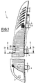
- a lamp 1 essentially consists of a mounting part 2, a mounting part 3 and a tab 4.
- the mounting part 2 is a housing part on a body 5 of a Vehicle rear light 1 to be trained.
- the tabs 4 are with their elongated holes 7 via fastening parts 8 arranged on the body 5 pluggable.
- the fastening parts 8 are designed as threaded bolts 9 which are attached at one end to the body 5 and at their free ends Have threads. The free ends of the threaded bolt 9 each protrude assembled state through the tabs 4.
- an outer wall 10 of the holding part 2 arranged opposite each other.
- On one of the walls 6, 10 connecting Rear wall 11 on the body 5 facing inside 12 three attachment parts 3 arranged.
- the attachment parts 3 each have an attachment longitudinal axis 13, which correspond approximately to them in the direction of the longitudinal axes 14 Ball bolts 15 are arranged.
- the ball pins 15 have one end attached to the body 5 cylindrical bolt body 16 on whose end facing away from the body 5 a ball head 17 is arranged.
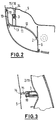
- the attachment part 3 points in the direction of expansion of the elongated hole 7, which is arranged in the vertical direction, one by one lateral opening 18 open ball socket 19 into which the ball head 17 of the Ball pin 15 can be engaged.
- the longitudinal axes 20 of the fastening parts 8 and the longitudinal axes 14 of the ball bolts 15 are approximately parallel to each other in the horizontal direction and in the direction arranged a vehicle longitudinal or body longitudinal axis, not shown.
- the attachment longitudinal axis 13 is approximately in the direction of the longitudinal axis 14 of the ball pin 15 arranged.
- the attachment part 3 has the holder part 2 on it facing away free end on an end opening 21 through which in the assembled State of the ball pin 15 with its bolt body 16 is passed.
- the front opening 21 has a clear width 22 which is larger than that Diameter of the bolt body 16 on the one hand and which is larger than the diameter the ball head 17 on the other hand.
- the front is in the vertical direction Opening 21 is formed much longer than the diameter of the ball head 17, so that a larger undercut is formed.
- the longitudinal axes also in the vertical direction or at an acute angle to the vehicle's longitudinal axis be arranged.
- the bracket part 2 is in an upper assembly position with its Tabs 4 inserted over the fasteners 8.
- the threaded bolts are located here 9 in a lower region of the elongated holes 7 and protrude with their free ends from the tabs 4 or the elongated holes 7.
- Move to a lower fixing position by moving the holder part 2 the tabs 4 in the vertical direction downwards so that the threaded bolts are located in an upper region of the elongated holes 7.
- the ball heads 17 are mounted with play in the ball socket 19.
- the tabs 4 are secured by nuts 23, which are attached to the threaded bolts 9 be screwed, screwed to the body. Disassembly is without Reverse problems possible. Alternatively, the shift of the holding part 2 also take place in the horizontal direction or obliquely, wherein the openings 18 of the spherical shells 19 are aligned accordingly.
- the front opening 21 can have an internal width 22 that is larger is than the diameter of the bolt body 16 on the one hand and which is smaller than the diameter of the ball head 17 on the other hand. This results in a Snap connection between the ball head 17 and the ball socket 19, which Attachment part 3 is designed as a locking part ..
- the mounting part 2 can also be attached to two attachment parts or only have a single attachment part which can be connected to the ball pin 15, so fewer parts are needed.
- the mounting direction can be horizontal or inclined to one Run vertical plane, the longitudinal axes of the fastening part 8 and Ball pins 15 run approximately parallel.
- the ball head 17 is slidable in the spherical shell 19 mounted, an automatic loosening due to the narrowing the lateral opening 21 in the transverse direction to the attachment longitudinal axis prevented becomes.
- the ball head 17 engages behind the attachment part 3.
Landscapes
- Engineering & Computer Science (AREA)
- Mechanical Engineering (AREA)
- Lighting Device Outwards From Vehicle And Optical Signal (AREA)
- Clamps And Clips (AREA)
- Pivots And Pivotal Connections (AREA)
- Connection Of Plates (AREA)
Abstract
Description
- Figur 1:
- Eine Vorderansicht einer Heckleuchte in verkleinerter Darstellung,
- Figur 2:
- eine Draufsicht auf die Leuchte von Figur 1 in einem entlang der Linie II - II geschnittenen Horizontalschnitt,
- Figur 3:
- einen Vertikalschnitt der Leuchte von Figur 1 entlang der Linie III - III geschnitten,
- Figur 4:
- einen Horizontalschnitt der Leuchte von Figur 1 entlang der Linie IV-IV geschnitten,
- Figur 5:
- eine Rückansicht der Leuchte von Figur 1 in räumlicher Darstellung,
- Figur 6:
- eine räumliche vergrößerte Darstellung eines Aufsetzteiles und eines Kugelbolzens und
- Figur 7:
- einen Vertikalschnitt durch ein Aufsetzteil in vergrößerter Darstellung.
Claims (10)
- Leuchte, insbesondere Heckleuchte für Kraftfahrzeuge, mit einem an einer Karosserie zu befestigenden Halterungsteil, das mit mindestens einer Lasche auf ein an der Karosserie angeordnetes Befestigungsteil aufsteckbar ist und das mindestens ein Aufsetzteil aufweist, das mit der Karosserie verbindbar ist, dadurch gekennzeichnet, dass die Lasche (4) ein Langloch (7) aufweist und dass das Aufsetzteil (3) eine in Ausdehnungsrichtung des Langloches (7) durch eine seitliche Öffnung (18) geöffnete Kugelschale (19) aufweist, in der ein an der Karosserie (3) angeordneter Kugelkopf (17) eines Kugelbolzens (16) hintergreifbar oder verrastbar angeordnet ist.
- Leuchte nach Anspruch 1, dadurch gekennzeichnet, dass das Langloch (7) der Lasche (4) in vertikaler Richtung angeordnet und die Kugelschale (19) in vertikaler Richtung nach unten geöffnet ist.
- Leuchte nach Anspruch 1 oder 2, dadurch gekennzeichnet, dass die Längsachsen (20, 14) vom Befestigungsteil (8) und vom Kugelbolzen (15) etwa parallel zueinander in horizontaler Richtung angeordnet sind.
- Leuchte nach Anspruch 3, dadurch gekennzeichnet, dass das Aufsetzteil (3) eine Aufsetzteillängsachse (13) aufweist, die etwa in Richtung der Längsachse (20) des Kugelbolzens (15) anordenbar ist.
- Leuchte nach einem der Anspruche 1 bis 4, dadurch gekennzeichnet, dass das Aufsetzteil (3) an seinem dem Halterungsteil (2) abgewandten freien Ende eine stirnseitige Öffnung (21) aufweist, durch die im montierten Zustand der Kugelbolzen (15) mit seinem Bolzenkörper (16) hindurchgeführt ist.
- Leuchte nach einem der Ansprüche 1 bis 5, dadurch gekennzeichnet, dass sich die Quererstreckung der seitlichen Öffnung (18) des Aufsetzteiles (3) in Richtung nach außen hin verringert.
- Leuchte nach einem der Ansprüche 1 bis 6, dadurch gekennzeichnet, dass das Halterungsteil (2) drei Laschen (4) und die Karosserie (5) drei mit den Laschen (4) korrespondierende Befestigungsteile (8) aufweist.
- Leuchte nach einem der Ansprüche 1 bis 7, dadurch gekennzeichnet, dass das Halterungsteil (2) drei Aufsetzteile (3) und die Karosserie (5) drei mit den Kugelschalen (19) der Aufsetzteile (3) korrespondierenden Kugelbolzen (15) aufweist.
- Leuchte nach einem der Ansprüche 1 bis 8, dadurch gekennzeichnet, dass das Befestigungsteil (8) als ein Gewindebolzen (9) ausgebildet ist, auf dem die Lasche (4) mit ihrem Langloch (7) aufsteckbar und durch eine Mutter (23) fixierbar ist.
- Leuchte nach einem der Ansprüche 1 bis 9, dadurch gekennzeichnet, dass in einer oberen Montagestellung des Halterungsteiles (2) die Gewindebolzen (9) in einem in vertikaler Richtung unteren Bereich der Langlöcher (7) der Laschen (4) angeordnet und die Aufsetzteile (3) mit den Kugelbolzen (15) nicht im Eingriff sind, und dass in einer unteren Fixierstellung der Halterung (2) die Gewindebolzen (9) in einem in vertikaler Richtung oberen Bereich der Langlöcher (7) angeordnet und die Aufsetzteile (3) mit den Kugelbolzen (15) verrastet sind.
Applications Claiming Priority (2)
| Application Number | Priority Date | Filing Date | Title |
|---|---|---|---|
| DE10045828A DE10045828B4 (de) | 2000-09-14 | 2000-09-14 | Leuchte für Fahrzeuge |
| DE10045828 | 2000-09-14 |
Publications (3)
| Publication Number | Publication Date |
|---|---|
| EP1193126A2 true EP1193126A2 (de) | 2002-04-03 |
| EP1193126A3 EP1193126A3 (de) | 2004-01-14 |
| EP1193126B1 EP1193126B1 (de) | 2004-12-22 |
Family
ID=7656431
Family Applications (1)
| Application Number | Title | Priority Date | Filing Date |
|---|---|---|---|
| EP01121959A Expired - Lifetime EP1193126B1 (de) | 2000-09-14 | 2001-09-12 | Leuchte für Fahrzeuge |
Country Status (3)
| Country | Link |
|---|---|
| EP (1) | EP1193126B1 (de) |
| DE (2) | DE10045828B4 (de) |
| ES (1) | ES2232554T3 (de) |
Families Citing this family (9)
| Publication number | Priority date | Publication date | Assignee | Title |
|---|---|---|---|---|
| DE20213362U1 (de) | 2002-08-30 | 2002-10-24 | Boellhoff Gmbh | Befestigungsanordnung für eine Heckleuchte |
| DE10306867B4 (de) * | 2003-02-19 | 2007-05-24 | Daimlerchrysler Ag | Heckleuchte eines Kraftfahrzeuges |
| DE102004030731B4 (de) * | 2004-06-25 | 2008-01-31 | Hella Kgaa Hueck & Co. | Vorrichtung zur Befestigung einer Leuchteneinheit an der Karosserie eines Fahrzeugs |
| DE102009011708B4 (de) * | 2009-03-09 | 2017-10-26 | Hella Kgaa Hueck & Co. | Fahrzeugleuchte |
| DE102012004748A1 (de) | 2012-03-08 | 2013-09-12 | GM Global Technology Operations LLC (n. d. Gesetzen des Staates Delaware) | Vorrichtung zum Befestigen einer Leuchteeines Kraftfahrzeuges an dessen Karosserie |
| DE102013001284A1 (de) * | 2013-01-25 | 2014-07-31 | GM Global Technology Operations LLC (n. d. Ges. d. Staates Delaware) | Vorrichtung zum Befestigen einer Leuchte an einer Fahrzeugkarosserie sowie Fahrzeugleuchte |
| DE102013102835B4 (de) * | 2013-03-20 | 2022-12-29 | HELLA GmbH & Co. KGaA | Beleuchtungsvorrichtung |
| DE102015213885B4 (de) | 2015-07-23 | 2022-12-01 | Volkswagen Aktiengesellschaft | Befestigungsanordnung für eine Beleuchtungsvorrichtung an einem Kraftfahrzeug |
| DE102015013622A1 (de) | 2015-10-20 | 2016-04-14 | Daimler Ag | Leuchte, insbesondere Heckleuchte, für einen Kraftwagen |
Citations (1)
| Publication number | Priority date | Publication date | Assignee | Title |
|---|---|---|---|---|
| DE19721596A1 (de) | 1997-05-23 | 1998-12-03 | Reitter & Schefenacker Gmbh | Leuchte, insbesondere Heckleuchte, für Fahrzeuge, vorzugsweise Kraftfahrzeuge |
Family Cites Families (8)
| Publication number | Priority date | Publication date | Assignee | Title |
|---|---|---|---|---|
| DE2250537C2 (de) * | 1972-10-14 | 1984-02-23 | Reitter & Schefenacker Kg, 7300 Esslingen | Kraftfahrzeug-Leuchtenfenster, insbesondere für Rückleuchten |
| DE2939595C2 (de) * | 1979-09-29 | 1983-12-08 | Adam Opel AG, 6090 Rüsselsheim | Kraftfahrzeugleuchte, insbesondere Blinkleuchte |
| JPS62139736A (ja) * | 1985-12-14 | 1987-06-23 | Ichikoh Ind Ltd | 車両用灯具 |
| US5269640A (en) * | 1991-06-03 | 1993-12-14 | Aoyama Seisakusho Co., Ltd. | Holding device for use in assembling mechanical members |
| FR2746728B1 (fr) * | 1996-03-28 | 1998-06-19 | Valeo Vision | Boitier pour dispositif d'eclairage ou de signalisation a moyens d'encliquetage, et dispositif ainsi equipe |
| DE19824051A1 (de) * | 1998-05-29 | 1999-12-02 | Hella Kg Hueck & Co | Tragelement |
| JP2000052852A (ja) * | 1998-08-04 | 2000-02-22 | Mitsubishi Motors Corp | ランプ取付構造 |
| JP3690133B2 (ja) * | 1998-08-28 | 2005-08-31 | 三菱自動車工業株式会社 | 自動車用ランプの取付構造 |
-
2000
- 2000-09-14 DE DE10045828A patent/DE10045828B4/de not_active Expired - Fee Related
-
2001
- 2001-09-12 ES ES01121959T patent/ES2232554T3/es not_active Expired - Lifetime
- 2001-09-12 EP EP01121959A patent/EP1193126B1/de not_active Expired - Lifetime
- 2001-09-12 DE DE50104869T patent/DE50104869D1/de not_active Expired - Lifetime
Patent Citations (1)
| Publication number | Priority date | Publication date | Assignee | Title |
|---|---|---|---|---|
| DE19721596A1 (de) | 1997-05-23 | 1998-12-03 | Reitter & Schefenacker Gmbh | Leuchte, insbesondere Heckleuchte, für Fahrzeuge, vorzugsweise Kraftfahrzeuge |
Also Published As
| Publication number | Publication date |
|---|---|
| DE50104869D1 (de) | 2005-01-27 |
| DE10045828B4 (de) | 2004-07-22 |
| EP1193126A3 (de) | 2004-01-14 |
| ES2232554T3 (es) | 2005-06-01 |
| DE10045828A1 (de) | 2002-04-04 |
| EP1193126B1 (de) | 2004-12-22 |
Similar Documents
| Publication | Publication Date | Title |
|---|---|---|
| DE69312795T2 (de) | Einbauelement für Beleuchtungs- oder Signaleinrichtung eines Kraftfahrzeugs | |
| DE4413635C2 (de) | Befestigungsvorrichtung für eine Scheibenwischeranlage | |
| DE102006004678B4 (de) | Montageeinheit für die Befestigungsöse eines Gurtschlosses | |
| DE102009016755B4 (de) | Verfahren und Befestigungsvorrichtungen zum Befestigen eines Fahrzeugteils | |
| DE69300045T2 (de) | Befestigung eines Wärmetauschers mit rohrförmiger Endkammer. | |
| DE102005044064A1 (de) | Schraubenverbindung mit Toleranzausgleich | |
| EP0639485A1 (de) | Befestigung für einen Sicherheitsgurt und die ihm zugehörigen Komponenten | |
| DE19900267A1 (de) | Vorrichtung zum Befestigen eines ersten Teils an einem feststehenden zweiten Teil | |
| EP2019765B1 (de) | Vorrichtung und verfahren zur befestigung eines wischermotors an ein wischergestänge | |
| EP1193126B1 (de) | Leuchte für Fahrzeuge | |
| DE69301453T2 (de) | Rohrbefestigungsanordnung | |
| DE69117867T2 (de) | Endauschlussstück | |
| EP4257832B1 (de) | Justageelement zum positionieren eines anbauteils | |
| EP1653555A2 (de) | Vorrichtung zum Kuppeln von Kabelsträngen mit einer Antenne | |
| DE102014009257B4 (de) | Exzenterelement und Verfahren zum Einstellen einer Relativposition eines Anbauteils | |
| DE69609675T2 (de) | Verbesserte Befestigungseinrichtung für Signalleuchte eines Fahrzeuges | |
| DE10029414B4 (de) | Instrumententafeleinbaukonstruktion | |
| DE10239740B4 (de) | Gehäuseinnenteil für eine Sicherheitsgurtaufrolleinrichtung | |
| DE4335042C2 (de) | Elektrische Lampenfassung aus Kunststoff | |
| DE4017701A1 (de) | Scheinwerfer fuer kraftfahrzeuge | |
| DE19735731A1 (de) | Kraftfahrzeugleuchte für den Einbau von außen | |
| EP0437211A1 (de) | Halterung zur Anbringung eines Anbauteils an einem Trägerstab | |
| DE60109676T2 (de) | Verriegelungsvorrichtung für eine Fahrzeugtür | |
| EP1384622B1 (de) | Leuchteinheit und Verfahren zum Befestigen einer Leuchteinheit | |
| DE102015226051A1 (de) | Anordnung eines Scheinwerfers gegenüber einem rohbauseitig festgelegten Trägerelement sowie Verfahren zur Feinjustierung eines lösbar befestigten Scheinwerfers gegenüber einem rohbauseitig festgelegten Trägerelement eines Kraftfahrzeugs |
Legal Events
| Date | Code | Title | Description |
|---|---|---|---|
| PUAI | Public reference made under article 153(3) epc to a published international application that has entered the european phase |
Free format text: ORIGINAL CODE: 0009012 |
|
| AK | Designated contracting states |
Kind code of ref document: A2 Designated state(s): AT BE CH CY DE DK ES FI FR GB GR IE IT LI LU MC NL PT SE TR |
|
| AX | Request for extension of the european patent |
Free format text: AL;LT;LV;MK;RO;SI |
|
| PUAL | Search report despatched |
Free format text: ORIGINAL CODE: 0009013 |
|
| AK | Designated contracting states |
Kind code of ref document: A3 Designated state(s): AT BE CH CY DE DK ES FI FR GB GR IE IT LI LU MC NL PT SE TR |
|
| AX | Request for extension of the european patent |
Extension state: AL LT LV MK RO SI |
|
| GRAP | Despatch of communication of intention to grant a patent |
Free format text: ORIGINAL CODE: EPIDOSNIGR1 |
|
| 17P | Request for examination filed |
Effective date: 20040210 |
|
| GRAS | Grant fee paid |
Free format text: ORIGINAL CODE: EPIDOSNIGR3 |
|
| AKX | Designation fees paid |
Designated state(s): DE ES FR IT |
|
| GRAA | (expected) grant |
Free format text: ORIGINAL CODE: 0009210 |
|
| RAP1 | Party data changed (applicant data changed or rights of an application transferred) |
Owner name: DAIMLERCHRYSLER AG Owner name: HELLA KGAA HUECK & CO. |
|
| AK | Designated contracting states |
Kind code of ref document: B1 Designated state(s): DE ES FR IT |
|
| REG | Reference to a national code |
Ref country code: IE Ref legal event code: FG4D Free format text: GERMAN |
|
| REF | Corresponds to: |
Ref document number: 50104869 Country of ref document: DE Date of ref document: 20050127 Kind code of ref document: P |
|
| REG | Reference to a national code |
Ref country code: ES Ref legal event code: FG2A Ref document number: 2232554 Country of ref document: ES Kind code of ref document: T3 |
|
| ET | Fr: translation filed | ||
| PGFP | Annual fee paid to national office [announced via postgrant information from national office to epo] |
Ref country code: ES Payment date: 20050927 Year of fee payment: 5 |
|
| PLBE | No opposition filed within time limit |
Free format text: ORIGINAL CODE: 0009261 |
|
| STAA | Information on the status of an ep patent application or granted ep patent |
Free format text: STATUS: NO OPPOSITION FILED WITHIN TIME LIMIT |
|
| 26N | No opposition filed |
Effective date: 20050923 |
|
| REG | Reference to a national code |
Ref country code: FR Ref legal event code: TQ |
|
| REG | Reference to a national code |
Ref country code: ES Ref legal event code: FD2A Effective date: 20060913 |
|
| PG25 | Lapsed in a contracting state [announced via postgrant information from national office to epo] |
Ref country code: ES Free format text: LAPSE BECAUSE OF NON-PAYMENT OF DUE FEES Effective date: 20060913 |
|
| PGFP | Annual fee paid to national office [announced via postgrant information from national office to epo] |
Ref country code: IT Payment date: 20070927 Year of fee payment: 7 |
|
| PGFP | Annual fee paid to national office [announced via postgrant information from national office to epo] |
Ref country code: FR Payment date: 20070926 Year of fee payment: 7 |
|
| REG | Reference to a national code |
Ref country code: FR Ref legal event code: ST Effective date: 20090529 |
|
| PG25 | Lapsed in a contracting state [announced via postgrant information from national office to epo] |
Ref country code: IT Free format text: LAPSE BECAUSE OF NON-PAYMENT OF DUE FEES Effective date: 20080912 |
|
| PG25 | Lapsed in a contracting state [announced via postgrant information from national office to epo] |
Ref country code: FR Free format text: LAPSE BECAUSE OF NON-PAYMENT OF DUE FEES Effective date: 20080930 |
|
| PGFP | Annual fee paid to national office [announced via postgrant information from national office to epo] |
Ref country code: DE Payment date: 20101103 Year of fee payment: 10 |
|
| PG25 | Lapsed in a contracting state [announced via postgrant information from national office to epo] |
Ref country code: DE Free format text: LAPSE BECAUSE OF NON-PAYMENT OF DUE FEES Effective date: 20130403 |
|
| REG | Reference to a national code |
Ref country code: DE Ref legal event code: R119 Ref document number: 50104869 Country of ref document: DE Effective date: 20130403 |