EP1192705B1 - Multi-resolution drive for actuators - Google Patents
Multi-resolution drive for actuators Download PDFInfo
- Publication number
- EP1192705B1 EP1192705B1 EP00944941A EP00944941A EP1192705B1 EP 1192705 B1 EP1192705 B1 EP 1192705B1 EP 00944941 A EP00944941 A EP 00944941A EP 00944941 A EP00944941 A EP 00944941A EP 1192705 B1 EP1192705 B1 EP 1192705B1
- Authority
- EP
- European Patent Office
- Prior art keywords
- signal
- control signal
- actuator
- magnitude
- armature
- Prior art date
- Legal status (The legal status is an assumption and is not a legal conclusion. Google has not performed a legal analysis and makes no representation as to the accuracy of the status listed.)
- Expired - Lifetime
Links
- 239000004020 conductor Substances 0.000 claims description 10
- 230000001419 dependent effect Effects 0.000 claims description 8
- 238000000034 method Methods 0.000 claims description 6
- 238000001914 filtration Methods 0.000 claims description 2
- 239000000654 additive Substances 0.000 abstract 1
- 230000000996 additive effect Effects 0.000 abstract 1
- 230000000694 effects Effects 0.000 description 4
- 238000010586 diagram Methods 0.000 description 2
- 230000003213 activating effect Effects 0.000 description 1
- 230000005291 magnetic effect Effects 0.000 description 1
- 238000004804 winding Methods 0.000 description 1
Images
Classifications
-
- H—ELECTRICITY
- H02—GENERATION; CONVERSION OR DISTRIBUTION OF ELECTRIC POWER
- H02K—DYNAMO-ELECTRIC MACHINES
- H02K41/00—Propulsion systems in which a rigid body is moved along a path due to dynamo-electric interaction between the body and a magnetic field travelling along the path
- H02K41/02—Linear motors; Sectional motors
- H02K41/035—DC motors; Unipolar motors
- H02K41/0352—Unipolar motors
- H02K41/0354—Lorentz force motors, e.g. voice coil motors
- H02K41/0356—Lorentz force motors, e.g. voice coil motors moving along a straight path
-
- H—ELECTRICITY
- H02—GENERATION; CONVERSION OR DISTRIBUTION OF ELECTRIC POWER
- H02K—DYNAMO-ELECTRIC MACHINES
- H02K33/00—Motors with reciprocating, oscillating or vibrating magnet, armature or coil system
- H02K33/18—Motors with reciprocating, oscillating or vibrating magnet, armature or coil system with coil systems moving upon intermittent or reversed energisation thereof by interaction with a fixed field system, e.g. permanent magnets
-
- H—ELECTRICITY
- H02—GENERATION; CONVERSION OR DISTRIBUTION OF ELECTRIC POWER
- H02P—CONTROL OR REGULATION OF ELECTRIC MOTORS, ELECTRIC GENERATORS OR DYNAMO-ELECTRIC CONVERTERS; CONTROLLING TRANSFORMERS, REACTORS OR CHOKE COILS
- H02P25/00—Arrangements or methods for the control of AC motors characterised by the kind of AC motor or by structural details
- H02P25/02—Arrangements or methods for the control of AC motors characterised by the kind of AC motor or by structural details characterised by the kind of motor
- H02P25/032—Reciprocating, oscillating or vibrating motors
- H02P25/034—Voice coil motors
Definitions
- the present invention relates to actuators, and more particularly to the drive for actuators, which may contain two or more inputs, one of which may be many times larger than the other.
- Actuators which may be used, for example, to position a device in a desired attitude are well-known in the art.
- the device is positioned by a first signal, herein called the coarse signal, usually from a computer through an amplifier to the actuator.
- the device being positioned may also be subject to undesirable changes of position due to, for example, vibration.
- an additional actuator has been heretofore employed to provide a second positioning signal, herein called the fine signal, to counteract the vibration (see WO95/16986).
- the fine signals may be several orders of magnitude smaller than the coarse, and so the problem of noise in the coarse signal presents a special problem since it may be in the same general magnitude as the fine signals.
- the noise in the coarse signal may swamp the fine signal so that the fine signals are lost. If the noise is filtered out by a low pass filter, then the fine signals may very well be filtered out also. Using a separate actuator for the fine signals is expensive, heavy and often nearly impossible without adding a second platform or stage for the device being positioned.
- the present invention overcomes the problems in the prior art by providing a multi-resolution drive having an actuator, a first and a second control signal source, a first and a second conductor coil and a filter.
- the actuator includes at least a stator and a movable armature, and the movable armature is operable to produce a force F having at least a first portion and a second portion.
- the first control signal source is configured to supply a first control signal representative of a first desired movement of the armature and includes noise therein.
- the second control signal source is configured to supply a second control signal representative of a second movement of the armature.
- the noise in the first control signal is of a magnitude at least as great as a magnitude of the second control signal.
- the first conductor coil is wrapped around the armature and connected to receive the first control signal, to thereby cause the armature to produce the first portion of the force, while the second conductor coil wrapped around the armature and connected to receive the second control signal, to thereby cause the armature to produce the second portion of the force, wherein the first portion of the force is at least an order of magnitude greater than the second portion of the force.
- the filter is connected between the first control signal source and the first conductor coil and operable to filter the noise therefrom.
- the present invention also provides a method of controlling the motion ofan actuator with two signals, the first of which would contain noise that would mask the second.
- the steps of the method include separately filtering the noise from the first signal, connecting the filtered first signal to the actuator, and independently connecting the second signal to the actuator so that the motion of the actuator has a first potion dependent on the magnitude of the filtered first signal and has a second; smaller portion dependent on the magnitude of the second signal.
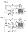
- a device to be controlled which, for purposes of this description will be considered to be a camera 10 is positioned by an actuator 14, in the form of a voice coil having an stator 16 and a movable armature 18, which operates to position camera 10 through a mechanical connection shown as dashed line 20.
- Amplifier 26 provides an output current, i coarse , at two output terminals 30 and 32 which are connected to a wire 34 wrapped a number of times, N, around the armature of the voice coil 14.
- Amplifier 26 preferably has an associated low pass filter, 35, which filters out the noise, and the output current, i coarse , acting through N turns, causes the armature 18 to exert a force F, on camera 10 through the mechanical connection 20.
- a position feedback shown by box 40 returns a signal via line 42 to controller 22 so that the motion caused by force, F, controls the camera 10 to the desired position.
- a sensor shown by box 46 which may be an accelerometer, produces a signal on a line 48 to controller 22 informing the computer of the vibration which the camera 10 maybe experiencing. Since the vibration effect is at least an order of magnitude smaller than the position effect, if the two signals were added directly, the noise in the position signal would be of the same magnitude as the vibration signal and would tend to mask it out. To avoid this, controller 22 produces an antivibration signal on an output line 50 which generally will be smaller in magnitude than the position signal on line 24.
- the signal on line 50 is presented to an amplifier 52 which produces an output current, i fine , at output terminals 54 and 56 connected to a wire 58 which is wrapped a number of times, n, around the armature of the voice coil 14.
- the output of amplifier 52 is of the same general order of magnitude as the output of amplifier 26 and accordingly, the number of turns, N, is made to be much larger than the number of turns, n.
- amplifier 52 may have a very small output compared to the output of amplifier 26 in which case, the number of turns, N, need not be so very much larger than n.
- the important feature is that the force produced by the anivibration signal be proportionately smaller than the force produced by the position control signal. This would normally be at least one order of magnitude. This is most easily accomplished by adjusting the number of turns N, to the number of turns n.
- Amplifier 52 may have an associated low pass filter, 59, therein to filter out any noise but the magnitude of this noise is so small that filter 59 is probably not necessary.
- the output current i fine adds a small force to the positioning force F which operates to null the vibration.
- B is a constant of magnitude which depends on the size and geometry of the magnetics in voice coil actuator, 14.
- a single actuator with two coils activating the armature, one coil having many turns and exerting a large influence on the movement of the armature and the other coil having few turns and exerting a proportionately smaller influence on the movement of the armature, a single actuator may be used.
- a third correction could be added in cases where a third and yet smaller variable is desired to be added to the force F.
- a third output, 65, from controller 22 would feed a third amplifier, 67, to produce a third, and yet smaller, current into a third winding, 70, around armature 18 to produce a third factor into the force F of considerably less effect than the position signal and the antivibration signal.
- the second output would be seperateldy filtered, as shown, and the third output independentldy connected to the coil 70, as shown, to provide protection in the same manner as the first and second outputs avoind the second output from being swamped by the first output.
Landscapes
- Engineering & Computer Science (AREA)
- Power Engineering (AREA)
- Physics & Mathematics (AREA)
- Chemical & Material Sciences (AREA)
- Combustion & Propulsion (AREA)
- Electromagnetism (AREA)
- Reciprocating, Oscillating Or Vibrating Motors (AREA)
- Control Of Position Or Direction (AREA)
- Ultra Sonic Daignosis Equipment (AREA)
- Investigating Or Analyzing Materials By The Use Of Ultrasonic Waves (AREA)
- Measurement Of Velocity Or Position Using Acoustic Or Ultrasonic Waves (AREA)
- Variable-Direction Aerials And Aerial Arrays (AREA)
- Vehicle Body Suspensions (AREA)
- Accessories Of Cameras (AREA)
- Studio Devices (AREA)
- Control Of Linear Motors (AREA)
Applications Claiming Priority (3)
| Application Number | Priority Date | Filing Date | Title |
|---|---|---|---|
| US342074 | 1999-06-28 | ||
| US09/342,074 US6278247B1 (en) | 1999-06-28 | 1999-06-28 | Multi-resolution drive for actuators |
| PCT/US2000/017749 WO2001001557A1 (en) | 1999-06-28 | 2000-06-28 | Multi-resolution drive for actuators |
Publications (2)
| Publication Number | Publication Date |
|---|---|
| EP1192705A1 EP1192705A1 (en) | 2002-04-03 |
| EP1192705B1 true EP1192705B1 (en) | 2005-11-16 |
Family
ID=23340221
Family Applications (1)
| Application Number | Title | Priority Date | Filing Date |
|---|---|---|---|
| EP00944941A Expired - Lifetime EP1192705B1 (en) | 1999-06-28 | 2000-06-28 | Multi-resolution drive for actuators |
Country Status (7)
| Country | Link |
|---|---|
| US (1) | US6278247B1 (enExample) |
| EP (1) | EP1192705B1 (enExample) |
| JP (1) | JP2003504002A (enExample) |
| AT (1) | ATE310334T1 (enExample) |
| AU (1) | AU5895800A (enExample) |
| DE (1) | DE60024089T2 (enExample) |
| WO (1) | WO2001001557A1 (enExample) |
Families Citing this family (1)
| Publication number | Priority date | Publication date | Assignee | Title |
|---|---|---|---|---|
| JP2003269692A (ja) * | 2002-03-12 | 2003-09-25 | Alps Electric Co Ltd | アクチュエータ及びこれを用いた光学装置 |
Family Cites Families (19)
| Publication number | Priority date | Publication date | Assignee | Title |
|---|---|---|---|---|
| US3984706A (en) * | 1971-12-27 | 1976-10-05 | Fujitsu Ltd. | Electromagnetic actuator for voice coil |
| US4075517A (en) * | 1976-04-02 | 1978-02-21 | Sperry Rand Corporation | Linear actuator |
| US4318038A (en) * | 1978-11-15 | 1982-03-02 | Nippon Electric Co., Ltd. | Moving-coil linear motor |
| US4612592A (en) * | 1979-12-26 | 1986-09-16 | Burroughs Corporation | Dual coil/dual magnet actuator |
| JPS5748103A (en) * | 1980-09-03 | 1982-03-19 | Hitachi Ltd | Servo-circuit system |
| US4669013A (en) * | 1985-04-02 | 1987-05-26 | International Business Machines Corporation | Multiple coils for reduction of stray magnetic fields in disk file actuators |
| US4751437A (en) * | 1986-03-26 | 1988-06-14 | Varian Associates, Inc. | Wide bandwidth linear motor system |
| JPS62254681A (ja) * | 1986-04-25 | 1987-11-06 | Hitachi Ltd | Xyステ−ジ |
| JPH01162279A (ja) * | 1987-12-18 | 1989-06-26 | Hitachi Ltd | 磁気デイスク装置の制御回路 |
| GB8920013D0 (en) * | 1989-09-05 | 1989-10-18 | Kelly H P G | Improvements in or relating to the control of linear motors |
| JPH0520812A (ja) * | 1991-07-12 | 1993-01-29 | Nec Corp | 磁気デイスク装置の磁気ヘツド位置決め装置 |
| JP3387173B2 (ja) * | 1993-10-27 | 2003-03-17 | ソニー株式会社 | 電磁駆動装置 |
| AU1339195A (en) * | 1993-12-15 | 1995-07-03 | Conner Peripherals, Inc | Voice coil driven positioner for coarse and fine positioning of magnetic head in multi-track tape drive |
| JPH0870567A (ja) * | 1994-08-26 | 1996-03-12 | Olympus Optical Co Ltd | ボイスコイルモータの制御装置 |
| JP3224489B2 (ja) * | 1995-03-28 | 2001-10-29 | キヤノン株式会社 | 空気バネ式除振装置 |
| JPH09121589A (ja) * | 1995-10-27 | 1997-05-06 | Hitachi Metals Ltd | リニアモータ |
| JP3825869B2 (ja) * | 1997-03-19 | 2006-09-27 | キヤノン株式会社 | 能動除振装置 |
| US5923487A (en) * | 1997-06-05 | 1999-07-13 | Maxtor Corporation | Integrated shock sensing device |
| JPH11102858A (ja) * | 1997-09-29 | 1999-04-13 | Canon Inc | ステージ位置決め制御装置および能動的除振装置 |
-
1999
- 1999-06-28 US US09/342,074 patent/US6278247B1/en not_active Expired - Lifetime
-
2000
- 2000-06-28 JP JP2001506671A patent/JP2003504002A/ja active Pending
- 2000-06-28 AT AT00944941T patent/ATE310334T1/de not_active IP Right Cessation
- 2000-06-28 DE DE60024089T patent/DE60024089T2/de not_active Expired - Fee Related
- 2000-06-28 AU AU58958/00A patent/AU5895800A/en not_active Abandoned
- 2000-06-28 EP EP00944941A patent/EP1192705B1/en not_active Expired - Lifetime
- 2000-06-28 WO PCT/US2000/017749 patent/WO2001001557A1/en not_active Ceased
Also Published As
| Publication number | Publication date |
|---|---|
| WO2001001557A1 (en) | 2001-01-04 |
| JP2003504002A (ja) | 2003-01-28 |
| US6278247B1 (en) | 2001-08-21 |
| ATE310334T1 (de) | 2005-12-15 |
| AU5895800A (en) | 2001-01-31 |
| DE60024089D1 (de) | 2005-12-22 |
| DE60024089T2 (de) | 2006-08-10 |
| EP1192705A1 (en) | 2002-04-03 |
Similar Documents
| Publication | Publication Date | Title |
|---|---|---|
| DE69627612T2 (de) | Frequenzselektiver aktiver adaptiver Steuerungsanordnung | |
| JP5166253B2 (ja) | 能動的に振動を減衰するためのシステムとその方法 | |
| US5459383A (en) | Robust active damping control system | |
| CN102245348B (zh) | 定位系统和方法 | |
| EP0767320A2 (en) | Vibration damping apparatus | |
| EP1026818B1 (en) | Motor speed controller and gain setting method of the controller | |
| JPH08234847A (ja) | 振動減衰装置 | |
| KR102248547B1 (ko) | 1차 데드비트 관측기를 이용한 위치 제어 시스템 및 제어방법 | |
| CN103547967A (zh) | 用于致动微光刻投影曝光设备中的元件的装置 | |
| EP1192705B1 (en) | Multi-resolution drive for actuators | |
| JP7108451B2 (ja) | 駆動制御装置、デバイス、光学モジュール、駆動制御方法、およびプログラム | |
| US20150066161A1 (en) | Controller for actuating a micromechanical actuator, actuating system for actuating a micromechanical actuator, micro-mirror system and method for actuating a micromechanical actuator | |
| KR20110135829A (ko) | 모터 구동 회로 | |
| JPH09121112A (ja) | 宇宙機搭載用光アンテナの指向角制御装置 | |
| DE102004033828A1 (de) | Verfahren und Vorrichtung zum Speichern von Daten auf Magnetband | |
| CA2472217A1 (en) | An active dynamic beater | |
| US11700488B2 (en) | Planar coil linear actuator and transducer | |
| GB2201262A (en) | Servo-valve control | |
| KR102276198B1 (ko) | 서보 시스템의 난제성 진동 제어 장치 및 방법 | |
| DE2420689A1 (de) | Verfahren und anordnung zur verbesserung der eigenschaften elektrodynamischer schwinger durch bewegungsgegenkopplung | |
| JPH06301948A (ja) | ヘッド駆動装置 | |
| JPH08241850A (ja) | 微動位置決め制御装置 | |
| SU1509841A1 (ru) | Регул тор дл виброзащитного устройства | |
| JPH11193847A (ja) | 除振制御方法および装置 | |
| JP7352281B2 (ja) | 動吸振器 |
Legal Events
| Date | Code | Title | Description |
|---|---|---|---|
| PUAI | Public reference made under article 153(3) epc to a published international application that has entered the european phase |
Free format text: ORIGINAL CODE: 0009012 |
|
| 17P | Request for examination filed |
Effective date: 20011218 |
|
| AK | Designated contracting states |
Kind code of ref document: A1 Designated state(s): AT BE CH CY DE DK ES FI FR GB GR IE IT LI LU MC NL PT SE |
|
| AX | Request for extension of the european patent |
Free format text: AL;LT;LV;MK;RO;SI |
|
| 17Q | First examination report despatched |
Effective date: 20030718 |
|
| GRAP | Despatch of communication of intention to grant a patent |
Free format text: ORIGINAL CODE: EPIDOSNIGR1 |
|
| GRAS | Grant fee paid |
Free format text: ORIGINAL CODE: EPIDOSNIGR3 |
|
| GRAA | (expected) grant |
Free format text: ORIGINAL CODE: 0009210 |
|
| AK | Designated contracting states |
Kind code of ref document: B1 Designated state(s): AT BE CH CY DE DK ES FI FR GB GR IE IT LI LU MC NL PT SE |
|
| PG25 | Lapsed in a contracting state [announced via postgrant information from national office to epo] |
Ref country code: IT Free format text: LAPSE BECAUSE OF FAILURE TO SUBMIT A TRANSLATION OF THE DESCRIPTION OR TO PAY THE FEE WITHIN THE PRESCRIBED TIME-LIMIT;WARNING: LAPSES OF ITALIAN PATENTS WITH EFFECTIVE DATE BEFORE 2007 MAY HAVE OCCURRED AT ANY TIME BEFORE 2007. THE CORRECT EFFECTIVE DATE MAY BE DIFFERENT FROM THE ONE RECORDED. Effective date: 20051116 Ref country code: NL Free format text: LAPSE BECAUSE OF FAILURE TO SUBMIT A TRANSLATION OF THE DESCRIPTION OR TO PAY THE FEE WITHIN THE PRESCRIBED TIME-LIMIT Effective date: 20051116 Ref country code: AT Free format text: LAPSE BECAUSE OF FAILURE TO SUBMIT A TRANSLATION OF THE DESCRIPTION OR TO PAY THE FEE WITHIN THE PRESCRIBED TIME-LIMIT Effective date: 20051116 Ref country code: BE Free format text: LAPSE BECAUSE OF FAILURE TO SUBMIT A TRANSLATION OF THE DESCRIPTION OR TO PAY THE FEE WITHIN THE PRESCRIBED TIME-LIMIT Effective date: 20051116 Ref country code: CH Free format text: LAPSE BECAUSE OF FAILURE TO SUBMIT A TRANSLATION OF THE DESCRIPTION OR TO PAY THE FEE WITHIN THE PRESCRIBED TIME-LIMIT Effective date: 20051116 Ref country code: FI Free format text: LAPSE BECAUSE OF FAILURE TO SUBMIT A TRANSLATION OF THE DESCRIPTION OR TO PAY THE FEE WITHIN THE PRESCRIBED TIME-LIMIT Effective date: 20051116 Ref country code: LI Free format text: LAPSE BECAUSE OF FAILURE TO SUBMIT A TRANSLATION OF THE DESCRIPTION OR TO PAY THE FEE WITHIN THE PRESCRIBED TIME-LIMIT Effective date: 20051116 |
|
| REG | Reference to a national code |
Ref country code: GB Ref legal event code: FG4D |
|
| REG | Reference to a national code |
Ref country code: CH Ref legal event code: EP |
|
| REG | Reference to a national code |
Ref country code: IE Ref legal event code: FG4D |
|
| REF | Corresponds to: |
Ref document number: 60024089 Country of ref document: DE Date of ref document: 20051222 Kind code of ref document: P |
|
| PG25 | Lapsed in a contracting state [announced via postgrant information from national office to epo] |
Ref country code: DK Free format text: LAPSE BECAUSE OF FAILURE TO SUBMIT A TRANSLATION OF THE DESCRIPTION OR TO PAY THE FEE WITHIN THE PRESCRIBED TIME-LIMIT Effective date: 20060216 Ref country code: SE Free format text: LAPSE BECAUSE OF FAILURE TO SUBMIT A TRANSLATION OF THE DESCRIPTION OR TO PAY THE FEE WITHIN THE PRESCRIBED TIME-LIMIT Effective date: 20060216 Ref country code: GR Free format text: LAPSE BECAUSE OF FAILURE TO SUBMIT A TRANSLATION OF THE DESCRIPTION OR TO PAY THE FEE WITHIN THE PRESCRIBED TIME-LIMIT Effective date: 20060216 |
|
| PG25 | Lapsed in a contracting state [announced via postgrant information from national office to epo] |
Ref country code: ES Free format text: LAPSE BECAUSE OF FAILURE TO SUBMIT A TRANSLATION OF THE DESCRIPTION OR TO PAY THE FEE WITHIN THE PRESCRIBED TIME-LIMIT Effective date: 20060227 |
|
| PG25 | Lapsed in a contracting state [announced via postgrant information from national office to epo] |
Ref country code: PT Free format text: LAPSE BECAUSE OF FAILURE TO SUBMIT A TRANSLATION OF THE DESCRIPTION OR TO PAY THE FEE WITHIN THE PRESCRIBED TIME-LIMIT Effective date: 20060417 |
|
| NLV1 | Nl: lapsed or annulled due to failure to fulfill the requirements of art. 29p and 29m of the patents act | ||
| REG | Reference to a national code |
Ref country code: CH Ref legal event code: PL |
|
| ET | Fr: translation filed | ||
| PG25 | Lapsed in a contracting state [announced via postgrant information from national office to epo] |
Ref country code: IE Free format text: LAPSE BECAUSE OF NON-PAYMENT OF DUE FEES Effective date: 20060628 |
|
| PG25 | Lapsed in a contracting state [announced via postgrant information from national office to epo] |
Ref country code: MC Free format text: LAPSE BECAUSE OF NON-PAYMENT OF DUE FEES Effective date: 20060630 |
|
| PLBE | No opposition filed within time limit |
Free format text: ORIGINAL CODE: 0009261 |
|
| STAA | Information on the status of an ep patent application or granted ep patent |
Free format text: STATUS: NO OPPOSITION FILED WITHIN TIME LIMIT |
|
| 26N | No opposition filed |
Effective date: 20060817 |
|
| REG | Reference to a national code |
Ref country code: IE Ref legal event code: MM4A |
|
| PG25 | Lapsed in a contracting state [announced via postgrant information from national office to epo] |
Ref country code: LU Free format text: LAPSE BECAUSE OF NON-PAYMENT OF DUE FEES Effective date: 20060628 |
|
| PG25 | Lapsed in a contracting state [announced via postgrant information from national office to epo] |
Ref country code: CY Free format text: LAPSE BECAUSE OF FAILURE TO SUBMIT A TRANSLATION OF THE DESCRIPTION OR TO PAY THE FEE WITHIN THE PRESCRIBED TIME-LIMIT Effective date: 20051116 |
|
| PGFP | Annual fee paid to national office [announced via postgrant information from national office to epo] |
Ref country code: FR Payment date: 20090605 Year of fee payment: 10 |
|
| PGFP | Annual fee paid to national office [announced via postgrant information from national office to epo] |
Ref country code: DE Payment date: 20090630 Year of fee payment: 10 |
|
| PGFP | Annual fee paid to national office [announced via postgrant information from national office to epo] |
Ref country code: GB Payment date: 20100401 Year of fee payment: 11 |
|
| REG | Reference to a national code |
Ref country code: FR Ref legal event code: ST Effective date: 20110228 |
|
| PG25 | Lapsed in a contracting state [announced via postgrant information from national office to epo] |
Ref country code: DE Free format text: LAPSE BECAUSE OF NON-PAYMENT OF DUE FEES Effective date: 20110101 |
|
| PG25 | Lapsed in a contracting state [announced via postgrant information from national office to epo] |
Ref country code: FR Free format text: LAPSE BECAUSE OF NON-PAYMENT OF DUE FEES Effective date: 20100630 |
|
| GBPC | Gb: european patent ceased through non-payment of renewal fee |
Effective date: 20110628 |
|
| PG25 | Lapsed in a contracting state [announced via postgrant information from national office to epo] |
Ref country code: GB Free format text: LAPSE BECAUSE OF NON-PAYMENT OF DUE FEES Effective date: 20110628 |
|
| P01 | Opt-out of the competence of the unified patent court (upc) registered |
Effective date: 20230525 |