EP1191832A2 - Automatic electronic parts mounting apparatus - Google Patents
Automatic electronic parts mounting apparatus Download PDFInfo
- Publication number
- EP1191832A2 EP1191832A2 EP01116540A EP01116540A EP1191832A2 EP 1191832 A2 EP1191832 A2 EP 1191832A2 EP 01116540 A EP01116540 A EP 01116540A EP 01116540 A EP01116540 A EP 01116540A EP 1191832 A2 EP1191832 A2 EP 1191832A2
- Authority
- EP
- European Patent Office
- Prior art keywords
- parts
- board
- mounting
- printed circuit
- circuit board
- Prior art date
- Legal status (The legal status is an assumption and is not a legal conclusion. Google has not performed a legal analysis and makes no representation as to the accuracy of the status listed.)
- Withdrawn
Links
Images





Classifications
-
- H—ELECTRICITY
- H05—ELECTRIC TECHNIQUES NOT OTHERWISE PROVIDED FOR
- H05K—PRINTED CIRCUITS; CASINGS OR CONSTRUCTIONAL DETAILS OF ELECTRIC APPARATUS; MANUFACTURE OF ASSEMBLAGES OF ELECTRICAL COMPONENTS
- H05K13/00—Apparatus or processes specially adapted for manufacturing or adjusting assemblages of electric components
- H05K13/0061—Tools for holding the circuit boards during processing; handling transport of printed circuit boards
- H05K13/0069—Holders for printed circuit boards
-
- Y—GENERAL TAGGING OF NEW TECHNOLOGICAL DEVELOPMENTS; GENERAL TAGGING OF CROSS-SECTIONAL TECHNOLOGIES SPANNING OVER SEVERAL SECTIONS OF THE IPC; TECHNICAL SUBJECTS COVERED BY FORMER USPC CROSS-REFERENCE ART COLLECTIONS [XRACs] AND DIGESTS
- Y10—TECHNICAL SUBJECTS COVERED BY FORMER USPC
- Y10T—TECHNICAL SUBJECTS COVERED BY FORMER US CLASSIFICATION
- Y10T29/00—Metal working
- Y10T29/53—Means to assemble or disassemble
- Y10T29/5313—Means to assemble electrical device
- Y10T29/53174—Means to fasten electrical component to wiring board, base, or substrate
-
- Y—GENERAL TAGGING OF NEW TECHNOLOGICAL DEVELOPMENTS; GENERAL TAGGING OF CROSS-SECTIONAL TECHNOLOGIES SPANNING OVER SEVERAL SECTIONS OF THE IPC; TECHNICAL SUBJECTS COVERED BY FORMER USPC CROSS-REFERENCE ART COLLECTIONS [XRACs] AND DIGESTS
- Y10—TECHNICAL SUBJECTS COVERED BY FORMER USPC
- Y10T—TECHNICAL SUBJECTS COVERED BY FORMER US CLASSIFICATION
- Y10T29/00—Metal working
- Y10T29/53—Means to assemble or disassemble
- Y10T29/5313—Means to assemble electrical device
- Y10T29/53174—Means to fasten electrical component to wiring board, base, or substrate
- Y10T29/53178—Chip component
Definitions
- the board holder is moved vertically by an electronic motor through a mechanism linkage.
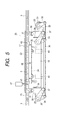
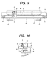
- the board holder includes an upper and a lower rail and a first urging member.
- One of the upper and lower rails has a vertically elongated hole into which a pin is inserted through the other of the upper and lower rails.
- the first urging member is disposed between the upper and lower rails to urge the upper and lower rails vertically in opposite directions.
- the board holding mechanism has a supporting member carried on a second urging member below the lower rail.
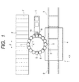
- a high-speed automatic parts mounting apparatus is provided which is designed to move pick-up nozzles vertically to mount electronic parts on a printed circuit board in sequence.
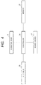
- the parts mounting apparatus reads data on height of each of the electronic parts out of a memory to determine a target level of the printed circuit when the electronic parts are mounted on the printed circuit board and moves an X-Y table on which the printed circuit board is held vertically to the target level.
- the level of the printed circuit board is adjusted based on the height of the electronic parts without changing a vertical stroke of the vacuum nozzles. This minimizes the vibration of the vacuum nozzles, thus avoiding a shift in orientation or mounted position of the electronic parts.
Landscapes
- Engineering & Computer Science (AREA)
- Manufacturing & Machinery (AREA)
- Microelectronics & Electronic Packaging (AREA)
- Supply And Installment Of Electrical Components (AREA)
Abstract
Description
Connected to the other ends of the
Claims (5)
- A parts mounting apparatus comprising:a parts feeder feeding parts;a board holding mechanism including a board holder which holds a board on which the parts are to be mounted at a parts mounting station, said board holder being designed to be moved vertically to hold the board at a given level;a parts mounting mechanism including a mounting unit, the mounting unit working to pick up one of the parts supplied from said parts feeder and move vertically along a vertical constant stoke to mount the picked up part on the board held by the board holder of said board holding mechanism;a storage storing therein parts data on height of each of the parts; anda controller determining a target level at which the board is to be held by the board holder of said board holding mechanism at the parts mounting station based on the parts data on the height of the part held by the mounting unit of said parts mounting mechanism and controlling an operation of said board holding mechanism to move the board holder vertically so that the board holder holds the board at the target level for mounting the part on the board at the parts mounting station.
- A parts mounting apparatus as set forth in claim 1, wherein said board holder is moved vertically by an electronic motor through a mechanism linkage.
- A parts mounting apparatus as set forth in claim 2, wherein the mechanical linkage is implemented by a lever linkage connecting at one end with an output shaft of the electronic motor and at the other end with said board holder.
- A parts mounting apparatus as set forth in claim 1, wherein said board holder includes an upper and a lower rail and a first urging member, one of the upper and lower rails having a vertically elongated hole into which a pin is inserted through the other of the upper and lower rails, the first urging member being disposed between the upper and lower rails to urge the upper and lower rails vertically in opposite directions, wherein said board holding mechanism has a supporting member carried on a second urging member below the lower rail, and wherein said controller moves the upper rail downward along with the lower rail with aid of urging pressure of the first urging member until the lower rail hits on the supporting member, lowers the upper rail further relative to the lower rail to nip the board between the upper rail and the lower rail, and lowers the upper rail further along with the lower rail against urging pressure of the second urging member to bring the board to the target level.
- A parts mounting apparatus as set forth in claim 1, wherein when it is required to mount parts of different height, the controller controls said mounting unit so as to mount the parts in order of having shorter height.
Applications Claiming Priority (2)
| Application Number | Priority Date | Filing Date | Title |
|---|---|---|---|
| JP2000290378 | 2000-09-25 | ||
| JP2000290378A JP2002100896A (en) | 2000-09-25 | 2000-09-25 | Component mounting machine |
Publications (2)
| Publication Number | Publication Date |
|---|---|
| EP1191832A2 true EP1191832A2 (en) | 2002-03-27 |
| EP1191832A3 EP1191832A3 (en) | 2003-07-09 |
Family
ID=18773616
Family Applications (1)
| Application Number | Title | Priority Date | Filing Date |
|---|---|---|---|
| EP01116540A Withdrawn EP1191832A3 (en) | 2000-09-25 | 2001-07-09 | Automatic electronic parts mounting apparatus |
Country Status (5)
| Country | Link |
|---|---|
| US (1) | US20020035781A1 (en) |
| EP (1) | EP1191832A3 (en) |
| JP (1) | JP2002100896A (en) |
| CN (2) | CN2513327Y (en) |
| DE (1) | DE20112150U1 (en) |
Cited By (1)
| Publication number | Priority date | Publication date | Assignee | Title |
|---|---|---|---|---|
| CN104053352A (en) * | 2013-03-15 | 2014-09-17 | 先进装配系统有限责任两合公司 | Component carrier for recognizing vibrations during component assembly |
Families Citing this family (6)
| Publication number | Priority date | Publication date | Assignee | Title |
|---|---|---|---|---|
| JP4384439B2 (en) * | 2002-11-21 | 2009-12-16 | 富士機械製造株式会社 | Anti-substrate work machine, anti-substrate work system, and work head use preparation processing program for anti-substrate work machine |
| CN100551221C (en) * | 2003-04-22 | 2009-10-14 | 松下电器产业株式会社 | Devices for installing components |
| JP5670725B2 (en) * | 2010-12-28 | 2015-02-18 | 富士機械製造株式会社 | Electronic component allocation method and electronic component mounting method |
| CN107690273A (en) * | 2017-09-20 | 2018-02-13 | 广东腾山机器人有限公司 | Automate inserter |
| CN109362218B (en) * | 2018-11-30 | 2020-04-28 | 长安大学 | Spiral large-scale feeding system of compact chip mounter |
| JP7550670B2 (en) | 2021-02-03 | 2024-09-13 | 株式会社Fuji | Work machine and interference avoidance method |
Family Cites Families (5)
| Publication number | Priority date | Publication date | Assignee | Title |
|---|---|---|---|---|
| JPS63300600A (en) * | 1987-05-29 | 1988-12-07 | Fuji Kikai Seizo Kk | Method and apparatus for mounting electronic component |
| US5208975A (en) * | 1990-07-06 | 1993-05-11 | Matsushita Electric Industrial Co., Ltd. | Method and apparatus for mounting electronic parts |
| KR100329586B1 (en) * | 1993-10-29 | 2002-09-19 | 산요 덴키 가부시키가이샤 | Electronic parts auto-mounting apparatus and mounting method thereof |
| JPH09326595A (en) * | 1996-06-06 | 1997-12-16 | Matsushita Electric Ind Co Ltd | Component mounting method |
| US5964031A (en) * | 1997-09-09 | 1999-10-12 | Mcms, Inc. | Method for supporting printed circuit board assemblies |
-
2000
- 2000-09-25 JP JP2000290378A patent/JP2002100896A/en active Pending
-
2001
- 2001-07-09 DE DE20112150U patent/DE20112150U1/en not_active Expired - Lifetime
- 2001-07-09 EP EP01116540A patent/EP1191832A3/en not_active Withdrawn
- 2001-09-25 CN CN01263663.0U patent/CN2513327Y/en not_active Expired - Fee Related
- 2001-09-25 CN CN01140972.XA patent/CN1347282A/en active Pending
- 2001-09-25 US US09/961,243 patent/US20020035781A1/en not_active Abandoned
Cited By (2)
| Publication number | Priority date | Publication date | Assignee | Title |
|---|---|---|---|---|
| CN104053352A (en) * | 2013-03-15 | 2014-09-17 | 先进装配系统有限责任两合公司 | Component carrier for recognizing vibrations during component assembly |
| CN104053352B (en) * | 2013-03-15 | 2017-04-12 | 先进装配系统有限责任两合公司 | Component carrier for recognizing vibrations during component assembly |
Also Published As
| Publication number | Publication date |
|---|---|
| DE20112150U1 (en) | 2002-01-17 |
| CN1347282A (en) | 2002-05-01 |
| US20020035781A1 (en) | 2002-03-28 |
| EP1191832A3 (en) | 2003-07-09 |
| JP2002100896A (en) | 2002-04-05 |
| CN2513327Y (en) | 2002-09-25 |
Similar Documents
| Publication | Publication Date | Title |
|---|---|---|
| JP3149782B2 (en) | Die bonding apparatus and die bonding method | |
| US6000123A (en) | Electronic-parts mounting apparatus | |
| US7100506B2 (en) | Plate supplying apparatus | |
| CA1116646A (en) | Tilting endless belt conveyor service by moving means | |
| CN1112590C (en) | Picking up and putting on device of mechanic finger system for testing semiconductor device | |
| JPH08118005A (en) | Solder ball mounting device and solder ball mounting method | |
| EP0779777A1 (en) | Automatic electronic parts mounting apparatus | |
| KR101056141B1 (en) | PCB Laser Marking Device | |
| US5682675A (en) | Apparatus and method of mounting electronic components | |
| EP1191832A2 (en) | Automatic electronic parts mounting apparatus | |
| JP2005175459A (en) | Tray feeder | |
| KR20140091486A (en) | Electronic component mounting apparatus | |
| JPH083035Y2 (en) | Substrate support device | |
| CN115159019B (en) | An automatic magnetizing laser engraving device | |
| CN216968828U (en) | Sticker device | |
| KR100631222B1 (en) | Component placement device | |
| JPH0985695A (en) | Parts supply device | |
| CN114228249A (en) | Sticker device, control method of sticker device | |
| JP3240746B2 (en) | Printed circuit board holding method and apparatus | |
| JP2002106558A (en) | Linear guide and electronic component mounting device | |
| CN119057461B (en) | Automatic assembly mechanism for buffer pulley, slider and oil cylinder | |
| JPH1032399A (en) | Electronic component mounting device | |
| KR0143000B1 (en) | Control apparatus of chip mounter | |
| KR200142977Y1 (en) | Pick-up and transfer apparatus of lead frame | |
| WO2026018425A1 (en) | Substrate work machine |
Legal Events
| Date | Code | Title | Description |
|---|---|---|---|
| PUAI | Public reference made under article 153(3) epc to a published international application that has entered the european phase |
Free format text: ORIGINAL CODE: 0009012 |
|
| AK | Designated contracting states |
Kind code of ref document: A2 Designated state(s): AT BE CH CY DE DK ES FI FR GB GR IE IT LI LU MC NL PT SE TR |
|
| AX | Request for extension of the european patent |
Free format text: AL;LT;LV;MK;RO;SI |
|
| PUAL | Search report despatched |
Free format text: ORIGINAL CODE: 0009013 |
|
| AK | Designated contracting states |
Designated state(s): AT BE CH CY DE DK ES FI FR GB GR IE IT LI LU MC NL PT SE TR |
|
| AX | Request for extension of the european patent |
Extension state: AL LT LV MK RO SI |
|
| RIC1 | Information provided on ipc code assigned before grant |
Ipc: 7H 05K 13/00 B Ipc: 7H 05K 13/04 A |
|
| 17P | Request for examination filed |
Effective date: 20030822 |
|
| AKX | Designation fees paid |
Designated state(s): DE FR GB |
|
| 17Q | First examination report despatched |
Effective date: 20071019 |
|
| STAA | Information on the status of an ep patent application or granted ep patent |
Free format text: STATUS: THE APPLICATION IS DEEMED TO BE WITHDRAWN |
|
| 18D | Application deemed to be withdrawn |
Effective date: 20080301 |