EP1191324B1 - Apparatus for measuring surface particulate contamination - Google Patents
Apparatus for measuring surface particulate contamination Download PDFInfo
- Publication number
- EP1191324B1 EP1191324B1 EP01307969A EP01307969A EP1191324B1 EP 1191324 B1 EP1191324 B1 EP 1191324B1 EP 01307969 A EP01307969 A EP 01307969A EP 01307969 A EP01307969 A EP 01307969A EP 1191324 B1 EP1191324 B1 EP 1191324B1
- Authority
- EP
- European Patent Office
- Prior art keywords
- smear
- diameter section
- contamination
- spool
- reflectivity
- Prior art date
- Legal status (The legal status is an assumption and is not a legal conclusion. Google has not performed a legal analysis and makes no representation as to the accuracy of the status listed.)
- Expired - Lifetime
Links
- 238000011109 contamination Methods 0.000 title claims description 38
- 239000006260 foam Substances 0.000 claims description 8
- 239000004744 fabric Substances 0.000 claims description 5
- 239000012858 resilient material Substances 0.000 claims description 5
- 239000004821 Contact adhesive Substances 0.000 claims description 3
- 238000002310 reflectometry Methods 0.000 description 35
- 238000005259 measurement Methods 0.000 description 23
- 238000000034 method Methods 0.000 description 18
- 239000000523 sample Substances 0.000 description 14
- 238000005070 sampling Methods 0.000 description 13
- 238000012360 testing method Methods 0.000 description 11
- 238000013459 approach Methods 0.000 description 8
- 239000000356 contaminant Substances 0.000 description 8
- 239000000463 material Substances 0.000 description 8
- 230000003749 cleanliness Effects 0.000 description 6
- 238000005299 abrasion Methods 0.000 description 4
- 230000000694 effects Effects 0.000 description 4
- 239000012530 fluid Substances 0.000 description 4
- 239000002245 particle Substances 0.000 description 4
- 238000004458 analytical method Methods 0.000 description 3
- 230000008901 benefit Effects 0.000 description 3
- 239000000126 substance Substances 0.000 description 3
- 238000012951 Remeasurement Methods 0.000 description 2
- 239000011248 coating agent Substances 0.000 description 2
- 238000000576 coating method Methods 0.000 description 2
- 238000004519 manufacturing process Methods 0.000 description 2
- 239000002184 metal Substances 0.000 description 2
- 229910052751 metal Inorganic materials 0.000 description 2
- 230000003746 surface roughness Effects 0.000 description 2
- 238000012546 transfer Methods 0.000 description 2
- 229920000742 Cotton Polymers 0.000 description 1
- LFQSCWFLJHTTHZ-UHFFFAOYSA-N Ethanol Chemical compound CCO LFQSCWFLJHTTHZ-UHFFFAOYSA-N 0.000 description 1
- 241001085205 Prenanthella exigua Species 0.000 description 1
- 239000004809 Teflon Substances 0.000 description 1
- 229920006362 Teflon® Polymers 0.000 description 1
- 239000000853 adhesive Substances 0.000 description 1
- 230000001070 adhesive effect Effects 0.000 description 1
- 239000002390 adhesive tape Substances 0.000 description 1
- 230000002411 adverse Effects 0.000 description 1
- 230000032683 aging Effects 0.000 description 1
- 230000003321 amplification Effects 0.000 description 1
- 230000009286 beneficial effect Effects 0.000 description 1
- 238000013461 design Methods 0.000 description 1
- 239000000428 dust Substances 0.000 description 1
- 239000007788 liquid Substances 0.000 description 1
- 150000002739 metals Chemical class 0.000 description 1
- 239000000203 mixture Substances 0.000 description 1
- 238000003199 nucleic acid amplification method Methods 0.000 description 1
- 230000003287 optical effect Effects 0.000 description 1
- 239000004033 plastic Substances 0.000 description 1
- 229920000642 polymer Polymers 0.000 description 1
- 238000003825 pressing Methods 0.000 description 1
- 238000011002 quantification Methods 0.000 description 1
- 230000003014 reinforcing effect Effects 0.000 description 1
- 230000000717 retained effect Effects 0.000 description 1
- 238000002791 soaking Methods 0.000 description 1
- 239000007921 spray Substances 0.000 description 1
- BFKJFAAPBSQJPD-UHFFFAOYSA-N tetrafluoroethene Chemical compound FC(F)=C(F)F BFKJFAAPBSQJPD-UHFFFAOYSA-N 0.000 description 1
- 238000012876 topography Methods 0.000 description 1
- 238000012549 training Methods 0.000 description 1
- 239000002023 wood Substances 0.000 description 1
Images
Classifications
-
- G—PHYSICS
- G01—MEASURING; TESTING
- G01N—INVESTIGATING OR ANALYSING MATERIALS BY DETERMINING THEIR CHEMICAL OR PHYSICAL PROPERTIES
- G01N15/00—Investigating characteristics of particles; Investigating permeability, pore-volume or surface-area of porous materials
- G01N15/06—Investigating concentration of particle suspensions
-
- G—PHYSICS
- G01—MEASURING; TESTING
- G01N—INVESTIGATING OR ANALYSING MATERIALS BY DETERMINING THEIR CHEMICAL OR PHYSICAL PROPERTIES
- G01N1/00—Sampling; Preparing specimens for investigation
- G01N1/02—Devices for withdrawing samples
-
- G—PHYSICS
- G01—MEASURING; TESTING
- G01N—INVESTIGATING OR ANALYSING MATERIALS BY DETERMINING THEIR CHEMICAL OR PHYSICAL PROPERTIES
- G01N1/00—Sampling; Preparing specimens for investigation
- G01N1/02—Devices for withdrawing samples
- G01N2001/028—Sampling from a surface, swabbing, vaporising
Definitions
- This invention relates generally to cleanliness measurement and more particularly to a quantitative measurement of surface particulate contamination of mechanical system components.
- a number of approaches to verify surface cleanliness of mechanical system components has been proposed.
- One such approach is the well known "white glove test” in which an inspector wipes a gloved finger across the surface of the component for some distance, and then observes the resultant stain on the finger. The inspector is then required to make an arbitrary decision as to the amount of contamination removed based on the darkness of the stain.
- This approach is highly subjective and varies greatly from test-to-test and from inspector-to-inspector.
- a more objective approach involves measuring particulate concentrations in the fluids used to wash the components. The fluid concentrations are typically determined using light attenuation or refraction, often with laser beams. However, this approach does not lend itself to practical, economic use on a mechanical assembly floor.
- the present invention defined in claim 1 consists of an apparatus for collecting a contamination sample for measuring surface particulate contamination, said apparatus comprising a tool for collecting a contamination sample from a target surface, a mask having an opening of known area formed therein for defining the target surface, and a flexible connector connecting the tool to the mask.
- the tool includes a body portion having a large diameter section defining a spherically convex surface and a small diameter section extending from the large diameter section.
- a particulate collector is removably mounted on the surface of the large diameter section for collecting the contaminants. Further aspects of the invention are defined in claims 2-6.
- the tool further includes a spindle extending from the small diameter section and a spool slidingly mounted on the spindle.
- a spring is disposed between the small diameter section and the spool for biasing the spool away from the small diameter section.
- An indicator is provided on the spindle so as to be revealed when the spool is pressed downward to compress the spring.
- the present invention involves determining the cleanliness of a component surface by measuring the surface particulate contamination. This is accomplished by a procedure that is a quantification of the well-known "white glove” test often used by inspectors.
- a bright, white cloth swatch (referred to herein as a "smear") is first rubbed in a prescribed manner over a test surface, which is a known clean surface similar in surface roughness to the target surface on the component to be sampled.
- the purpose of rubbing a clean test surface is to precondition the smear for reflectivity loss that is solely attributable to abrasion effects.
- the roughened but still clean smear is then measured for its reflectivity using a reflectivity measuring instrument.
- the smear is rubbed in a prescribed manner over the target surface to obtain a sample of the contamination on the target surface.
- the reflectivity of the smear is then measured again and compared to the first reflectivity measurement to determine the loss of reflectivity that is attributable to the contamination on the target surface.
- the loss of reflectivity is then related, through empirical calibration, to the amount of contamination that was transferred to the smear in the rubbing of the target surface.
- the procedure provides a quantified measurement of the surface contamination of the component that can be used as an objective "go/no go" indication for assembly. In other words, if the measured level of contamination is below a maximum acceptable level, then the component can go on to assembly. But if the measured contamination is above the acceptable level, then the component will need to be re-cleaned and re-checked prior to assembly.
- US 5 373 748 A discloses a portable sampler having a dust pick-up element and a corresponding template having an aperture which exposes a testing surface of predetermined area.
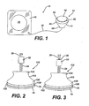
- Figure 1 shows an exemplary apparatus 10 according to the invention for collecting the contamination sample.
- the apparatus 10 includes a hand tool 12 on which a particulate collector such as a white cloth smear 14 can be mounted and a mask 16 for delineating the area of the target surface to be sampled.
- the tool 12 and mask 16 are connected by a flexible connector 18 such as a string, cord or the like to insure that neither piece is inadvertently left behind after the measurement is completed.
- the tool 12 includes a mushroom-shaped body portion 13 having a large diameter section 20 defining a spherically convex surface 22 and a small diameter section 24 extending from the large diameter section 20.
- the body portion 13 can comprise a commercially available knob of the type commonly used as a drawer pull or a handle for a cupboard door and typically made of wood, plastic, metal or the like.
- the smear 14 is mounted onto the spherically convex surface 22 so that the tool 12 can be used by grasping the small diameter section 24 and wiping the smear 14 over the target surface.
- the convex configuration of the smear 14 allows control of the leading interface of the smear 14 with the target surface during wiping.
- a thin layer 26 of a resilient material such as foam is interposed between the convex surface 22 and the smear 14.
- a resilient material refers to materials that are compressible under the mentioned load and are also elastic.
- the foam layer 26, which can be approximately 1/8 inches (3.2mm) thick, is fixedly secured to the convex surface 22 by any suitable means such as adhesive.
- the resilient foam 26 more uniformly distributes the pressure with which the tool 12 is applied to the target surface, thereby diffusing the load over a larger area so as to increase the contact area between the smear 14 and the target surface.
- the foam 26 is also elastic so as to retain its original shape after the compressive force is relieved.
- the mask 16 comprises a thin sheet of a relatively stiff material that is thin enough (approximately 1/16 inch (1.6mm)) to be somewhat flexible.
- a relatively stiff material is thin enough (approximately 1/16 inch (1.6mm)) to be somewhat flexible.
- One suitable material is a polytetrafluoroethlene polymer, such as that commercially available under the trademark TEFLON.
- An opening 28 of known area is formed in the mask 16 for limiting the area of the target surface that is to be sampled.
- the opening 28 is preferably, but not necessarily, circular in shape.
- the edge of the opening 28 is chamfered on the top side to prevent contamination from being caught therein.
- the mask 16 can be used on both flat surfaces and non-flat surfaces such as the interior of large pipes.
- the smear 14 is a circular, white cloth swatch sized to fit onto the convex surface 22.
- One suitable smear is commercially available from D. A. Services, Inc. of Windsor, Connecticut. These smears are bright white cloth disks 1 3/4 inches (44 ⁇ 45 mm) in diameter and come stored in a waxed paper folder that can be labeled for archiving.
- the smears also have a multi-use contact adhesive backing (not shown in Figure 1 ) that allows them to be removably mounted on the foam layer 26.
- the large diameter section of the hand tool 12 preferably has a 2 inch (50 ⁇ 8mm) diameter and the mask opening 28 is preferably a 6 inch (152mm) diameter circle.
- the first step is to select a new smear for the measurement and measure its reflectivity to simply verify that the smear is new and unused. This is done by opening the smear folder and measuring the smear reflectivity once or twice with a reflectivity measuring instrument. The actual reflectivity value is recorded. Any suitable instrument can be used for this purpose.
- One suitable commercially available device is the Photovolt Model 577 from UMM Electronics of Indianapolis, Indiana. This device includes a reflectivity meter and sensor set up to operate with a blue filter where the smear is pressed against the face of the sensor head.
- the sensor head has a 3/4 inch (19mm) hole in its distal end and contains both a light source and a photomultiplier, which illuminate and measure reflectance from objects placed against the hole.
- the next step is to remove the smear 14 from its paper folder and place it in position on the convex surface 22 of the tool 12. This is preferably done using tweezers so as to avoid contaminating the smear 14 prior to the measurement.
- the smear 14 is wiped in a prescribed manner over a test surface to precondition the smear 14 for reflectivity loss that is solely attributable to abrasion effects.
- the test surface is a known clean surface similar in surface roughness to the target surface to be sampled.
- One preferred test surface is a small portion of the component surface being measured that has been sufficiently cleaned so that all contamination is known to have been removed.
- test surface should be a non-sampled section of the surface that has been wiped clean using an alcohol-based cleaner and a laboratory paper towel. If the component surface has been cleaned but not subjected to oil removal processes, the test surface should be a non-sampled section of the component surface that has been wiped clean twice with a clean, dry cotton rag, wiping hard (approximately 2 lbf (0.91 kgf)).
- the smear 14 is transferred back to its folder, again using tweezers.
- the reflectivity of the roughened but still clean smear is then measured using the reflectivity measuring instrument while the smear 14 is mounted in its folder.
- a 5-point measurement of reflectivity is obtained, taking the measurements 1/4 inch (0 ⁇ 635cm) off the smear center in each direction, with each measurement representing a substantially different area of the smear 14.
- the results of the five measurements are then averaged to obtain a single reflectivity value for the smear 145. All of the measurements are recorded on the folder.
- the smear 14 is then removed from the folder again and remounted on the tool 12 for a target surface sampling wipe.
- the mask 16 is placed on the component surface so as to define the target surface within the mask opening 28. This forces the sampling wipe to be conducted on a controlled region of known area.
- the smear 14 is wiped over the target surface in a prescribed manner to obtain a sample of the contamination on the component surface.
- the preconditioning wipe and the sampling wipe are preferably conducted in identical manners. In one preferred wiping procedure, the smear 14 is wiped over the target surface in a spiral motion, starting at the center of the masked opening 28 and moving outward to the edge of the opening 28 in gradually increasing circles.
- the tool 12 is held with its axis tilted so that the forward edge of the smear 14 is lifted as it passes over the target surface.
- the smear 14 is rotated into the direction of motion so as to continually provide a fresh surface of the smear 14 to pick up contamination.
- the wiping path approaches the chamfered edge of the mask opening 28, the tool 12 is further tilted so that the smear 14 rides up slightly over the mask 16 while the wiping motion is tangential to the edge.
- This overlap enables any contaminates that have been inadvertently rubbed onto the mask to be captured.
- the tangential motion minimizes the tendency to rub contamination from the target area out under the mask 16.
- each pass should be done with a relatively constant force and in a prescribed time period such as 5 seconds.
- a single wiping procedure will comprise two passes.
- the second pass not only collects residue contamination missed in the first pass, but will also further smudge the contamination around the smear 14 to provide a more uniform darkening thereof.
- Using more than two passes in a single wipe would only tend to have an adverse effect on the reflectivity measurement. For example, additional passes would tend to push the contamination from the surface of the smear 14 into its interior and degrade the smear surface with excessive abrasion.
- the smear 14 is removed from the tool 12 and returned to its folder with tweezers.
- the smear reflectivity after sampling is measured using the reflectivity measuring instrument as described above.
- the reflectivity measurement is preferably made a short time after the sampling, although it can be made at any time since the smear reflectivity value is not a sensitive function of aging.
- the reflectivity measurements, date and time of sampling, technician, component and target surface area are recorded on the folder.
- the amount of contamination collected from the target surface is determined by calculating the change in reflectivity of the smear as measured before and after the sampling and comparing that to a previous calibration using a similar contamination. As mentioned above, if the measured level of contamination is below a maximum acceptable level, then the component can go on to assembly. But if the measured contamination is above the acceptable level, then the component will need to be re-cleaned and re-checked prior to assembly.
- the smear 14 can be stored in its folder for later examination and comparisons. If the need arises, the smear 14 can be submitted for metals analysis by scanning electron microprobe. Moreover, wet chemical analyses can be done at a later time if desired to determine the exact chemical composition and contaminant loading. An unused smear should be retained with the archived smears on a regular basis (such as once per week or one per a 500 smear box). These unused smears serve as controls for later remeasurements of smear reflectivity or of contaminant concentrations.
- the calibration for determining the amount of contamination collected on the smear 14 can be performed as follows.
- a sample of representative contaminant material is collected from component surfaces or special specimens located in the assembly areas that contribute contamination. This sample contaminant material is carefully placed on a weigh paper and weighed in a laboratory balance to obtain the gross weight.
- a mask 16 is placed on a calibration surface, and the sample is distributed on the calibration target surface within the mask opening 28.
- the calibration surface is a flat plate of a material having the same roughness as the component surface to be sampled. The empty weigh paper is then reweighed to obtain the tare weight such that the net weight of the sample material can be determined.
- a clear, somewhat tacky coating to enable it to collect and hold large amounts of loose particles.
- a coating can be applied before the first pass of a sampling wipe, before the second pass of a sampling wipe, or before both passes.
- the presence of any remnant oil films on the target surface may dictate that the calibration surface be provided with the same level of oil film, since the oil (even without particles) will likely reduce the smear reflectivity.
- the presence of oil films could be dealt with by soaking the smear for a long time to vaporize the organics, leaving only the particulate contamination to affect the smear reflectivity.
- the tool 112 includes a mushroom-shaped body portion 113 having a large diameter section 120 defining a spherically convex surface 122 and a small diameter section 124 extending from the large diameter section 120.
- a smear 14 is mounted onto the spherically convex surface 122 with a thin layer 126 of a resilient material such as foam interposed between the convex surface 122 and the smear 14.
- the smear 14 includes a multi-use contact adhesive backing 15 for repeated and removable mounting to the foam layer 26.
- a spindle 30 extends axially from the end of the small diameter section 124.
- a spool 32 having a bore formed therein along its longitudinal axis is slidingly mounted on the spindle 30, and a spring 34 is disposed between the end of the small diameter section 124 and the spool 32 for biasing the spool 32 away from the small diameter section 124.
- a color band 36 or a similar indicator is formed on the spindle 30 at a location such that it is covered by the spool 32 when the spool 32 is in its normal position such that the spring 34 is in an uncompressed state ( Figure 2 ). Pressing the spool 32 downward along the spindle 30 to expose the color band 36 ( Figure 3 ) will cause the spring 34 to be compressed.
- a wiping procedure be it a preconditioning wipe, a sampling wipe or a calibration wipe
- the operator will hold the sliding spool 32 and press it downward to expose the color band 36. This will allow the operator to press the tool and smear 14 against the surface with a known amount of force (about 170-210g), so as to insure uniform application of the tool 112 during each procedure.
- the foregoing has described a method and apparatus for measuring surface particulate contamination.
- the present invention has several benefits for use on the factory floor. For example, because the stain on the smear is very visible to the operator, the technique is intuitive and readily understood by the technician, even without technical training.
- the reflectivity measurement can be made on the factory floor within minutes of the smear being wiped on the target surface. This is very helpful in getting broad acceptance of the technique given the time pressures of a major manufacturing and assembly operation.
- the ability of the technician to conduct both the sampling and the reflectivity measurements improves the likelihood that the process will be consistently used, thereby continually reinforcing the need to work cleanly.
- the sample improvement will realize an order of magnitude improvement over using replicas, even if the smear collection was only 90% effective.
- Another advantage is that the smears can be easily archived in their folders for later remeasurement of reflectivity or for physical and/or chemical analysis of the contaminant material.
Landscapes
- Chemical & Material Sciences (AREA)
- Physics & Mathematics (AREA)
- Health & Medical Sciences (AREA)
- Life Sciences & Earth Sciences (AREA)
- Analytical Chemistry (AREA)
- Biochemistry (AREA)
- General Health & Medical Sciences (AREA)
- General Physics & Mathematics (AREA)
- Immunology (AREA)
- Pathology (AREA)
- Dispersion Chemistry (AREA)
- Sampling And Sample Adjustment (AREA)
Applications Claiming Priority (2)
| Application Number | Priority Date | Filing Date | Title |
|---|---|---|---|
| US09/670,452 US6382036B1 (en) | 2000-09-26 | 2000-09-26 | Apparatus for measuring surface particulate contamination |
| US670452 | 2003-09-24 |
Publications (3)
| Publication Number | Publication Date |
|---|---|
| EP1191324A2 EP1191324A2 (en) | 2002-03-27 |
| EP1191324A3 EP1191324A3 (en) | 2003-10-22 |
| EP1191324B1 true EP1191324B1 (en) | 2010-12-08 |
Family
ID=24690451
Family Applications (1)
| Application Number | Title | Priority Date | Filing Date |
|---|---|---|---|
| EP01307969A Expired - Lifetime EP1191324B1 (en) | 2000-09-26 | 2001-09-19 | Apparatus for measuring surface particulate contamination |
Country Status (5)
| Country | Link |
|---|---|
| US (1) | US6382036B1 (enExample) |
| EP (1) | EP1191324B1 (enExample) |
| JP (1) | JP2002131196A (enExample) |
| KR (1) | KR100659802B1 (enExample) |
| CZ (1) | CZ20012839A3 (enExample) |
Families Citing this family (23)
| Publication number | Priority date | Publication date | Assignee | Title |
|---|---|---|---|---|
| US6397690B1 (en) * | 2000-09-26 | 2002-06-04 | General Electric Company | Tools for measuring surface cleanliness |
| US8011258B2 (en) * | 2003-08-28 | 2011-09-06 | L-3 Communications Cyterra Corporation | Explosive residue sampling |
| KR100910906B1 (ko) | 2008-11-05 | 2009-08-05 | (주)코스코텍 | 방사능 표면오염 측정을 위한 균일압력기 |
| DE102008059112A1 (de) * | 2008-11-26 | 2010-06-17 | Eads Deutschland Gmbh | Probensammler und Probensammeleinrichtung für eine Analyseeinrichtung sowie Verfahren zu dessen Betrieb |
| CA2696647A1 (en) * | 2009-03-17 | 2010-09-17 | The Procter & Gamble Company | Demonstrative methods for paper towel products |
| EP2410317A1 (de) * | 2010-07-13 | 2012-01-25 | Krämer AG Bassersdorf | Verfahren zum Beurteilen von an einem Körper anhaftenden Partikeln |
| KR101289473B1 (ko) | 2013-01-22 | 2013-07-24 | 한국생산기술연구원 | 불균염 정량 시스템 및 이를 이용한 불균염 정량 방법 |
| US10082452B2 (en) | 2013-02-05 | 2018-09-25 | Pocared Diagnostics Ltd. | Filter arrangement and method for using the same |
| JP5924390B2 (ja) * | 2014-10-01 | 2016-05-25 | 三浦工業株式会社 | 試料採取ペン |
| DE102016119628A1 (de) * | 2016-10-14 | 2018-04-19 | Minebea Intec GmbH | Probensammler mit integriertem Kraftmesser |
| DE102016012369B3 (de) * | 2016-10-15 | 2017-02-23 | Bundesrepublik Deutschland, vertreten durch das Bundesministerium der Verteidigung, vertreten durch das Bundesamt für Ausrüstung, Informationstechnik und Nutzung der Bundeswehr | Probennahmekit für eine CBRN-Probe |
| EP3684944B1 (en) | 2017-09-21 | 2025-01-01 | Becton, Dickinson and Company | Hazardous contaminant collection kit and rapid testing |
| ES3037747T3 (en) | 2017-09-21 | 2025-10-06 | Becton Dickinson Co | Augmented reality devices for hazardous contaminant testing |
| AU2018337027B2 (en) | 2017-09-21 | 2024-06-06 | Becton, Dickinson And Company | Hazardous contaminant collection kit and rapid testing |
| CN209559735U (zh) | 2017-09-21 | 2019-10-29 | 贝克顿·迪金森公司 | 用于引导收集有害污染物样本的系统 |
| CN111107939B (zh) | 2017-09-21 | 2022-04-12 | 贝克顿·迪金森公司 | 引导有害污染物样品的收集的系统和模板及使用其的方法 |
| CN209400423U (zh) | 2017-09-21 | 2019-09-17 | 贝克顿·迪金森公司 | 横向流测定物、测定物读取器装置和包括其的系统 |
| CN111278987B (zh) | 2017-09-21 | 2024-02-23 | 贝克顿·迪金森公司 | 以高拾取和脱落效率收集有害污染物的采样系统和技术 |
| CN108827686B (zh) * | 2018-07-31 | 2023-07-25 | 河南师范大学 | 一种用于手掌灰尘样品采集以用于真皮暴露评估的手套 |
| CN113383222A (zh) | 2019-01-28 | 2021-09-10 | 贝克顿·迪金森公司 | 具有集成的拭子和测试装置的有害污染物收集装置 |
| CN109946109A (zh) * | 2019-03-20 | 2019-06-28 | 西安热工研究院有限公司 | 一种汽轮机叶片微量水溶性沉积物的取样和检测方法 |
| CZ309251B6 (cs) * | 2020-10-23 | 2022-06-22 | Univerzita Karlova | Způsob čištění a nedestruktivního sledování procesu čištění křemenných ampulí pro polovodičové technologie |
| JP7815782B2 (ja) * | 2022-01-19 | 2026-02-18 | 株式会社豊田中央研究所 | 生物由来核酸回収方法、および、生物由来核酸回収装置 |
Family Cites Families (16)
| Publication number | Priority date | Publication date | Assignee | Title |
|---|---|---|---|---|
| US3074276A (en) * | 1959-04-20 | 1963-01-22 | Walter S Moos | Radioactivity smear sampler |
| US3091967A (en) * | 1960-05-13 | 1963-06-04 | William R Hurdlow | Swipe sampler |
| FR1535675A (fr) * | 1967-06-28 | 1968-08-09 | Commissariat Energie Atomique | Dispositif de prélèvement, par frottement sur une surface, de traces de substances susceptibles d'être radioactives |
| JPS618388Y2 (enExample) * | 1980-08-11 | 1986-03-14 | ||
| JPS618389Y2 (enExample) * | 1980-08-11 | 1986-03-14 | ||
| JPS586290U (ja) * | 1981-07-03 | 1983-01-14 | 株式会社東芝 | 放射性物質の試料採取装置 |
| JPH0449595Y2 (enExample) * | 1985-08-07 | 1992-11-20 | ||
| JPS6235275U (enExample) * | 1985-08-20 | 1987-03-02 | ||
| JPS62143278U (enExample) * | 1986-03-05 | 1987-09-09 | ||
| JPS636375U (enExample) * | 1986-06-26 | 1988-01-16 | ||
| FR2622972B1 (fr) * | 1987-11-09 | 1990-03-16 | Inhni | Procede de controle de proprete d'une surface et dispositif pour la mise en oeuvre dudit procede |
| US5373748A (en) * | 1992-09-22 | 1994-12-20 | University Of Medicine And Dentistry Of New Jersey | Wipe template sampler |
| JPH075264A (ja) * | 1993-06-16 | 1995-01-10 | Fuji Electric Co Ltd | 表面汚染検査装置、該検査装置のスミヤパッド及び該スミヤパッドのスミヤろ紙自動交換装置 |
| CA2137604A1 (en) * | 1994-12-08 | 1996-06-09 | Gerald Drolet | Apparatus and method for collecting samples for ims(ion mobility spectrometers) analyzers and the like |
| US5939647A (en) * | 1996-01-16 | 1999-08-17 | Applied Materials, Inc. | Surface particle sampling head having a rotatable probe |
| US5859375A (en) * | 1996-04-03 | 1999-01-12 | Barringer Research Limited | Apparatus for and method of collecting trace samples for analysis |
-
2000
- 2000-09-26 US US09/670,452 patent/US6382036B1/en not_active Expired - Fee Related
-
2001
- 2001-08-03 CZ CZ20012839A patent/CZ20012839A3/cs unknown
- 2001-09-19 EP EP01307969A patent/EP1191324B1/en not_active Expired - Lifetime
- 2001-09-25 KR KR1020010059396A patent/KR100659802B1/ko not_active Expired - Fee Related
- 2001-09-25 JP JP2001290338A patent/JP2002131196A/ja not_active Ceased
Also Published As
| Publication number | Publication date |
|---|---|
| JP2002131196A (ja) | 2002-05-09 |
| KR100659802B1 (ko) | 2006-12-19 |
| EP1191324A3 (en) | 2003-10-22 |
| CZ20012839A3 (cs) | 2002-05-15 |
| EP1191324A2 (en) | 2002-03-27 |
| US6382036B1 (en) | 2002-05-07 |
| KR20020024799A (ko) | 2002-04-01 |
Similar Documents
| Publication | Publication Date | Title |
|---|---|---|
| EP1191324B1 (en) | Apparatus for measuring surface particulate contamination | |
| US6378386B1 (en) | Surface cleanliness measurement procedure | |
| JP5361391B2 (ja) | サンプリング装置 | |
| US6507393B2 (en) | Surface cleaning and particle counting | |
| US5373748A (en) | Wipe template sampler | |
| Campbell et al. | Measurement of aerosol absorption coefficient from Teflon filters using integrating plate and integrating sphere techniques | |
| US5649447A (en) | Non destructive paint and bonding adhesion prediction meter (APM) for metal surfaces | |
| US20020101584A1 (en) | Surface cleaning and particle counting | |
| EP1896810A2 (en) | Verification apparatus and methods for optical inspection machine | |
| US20110293151A1 (en) | Method and device for quantifying surface particulate contaminants by improved analysis | |
| WO2002065054A1 (en) | Method and device for measuring inner diameter dimension of work | |
| JPH09257788A (ja) | CrMoV鋼材におけるクリープ損傷の非破壊的判定方法 | |
| CN115413332A (zh) | 测试表面粒子污染的粒子测试系统、采样条、投射曝光设备和方法 | |
| Pecault et al. | Performance assessment of probes dedicated to the monitoring of surface particle contamination | |
| Chawla | 1 How Clean Is Clean? Measuring Surface Cleanliness and Defining Acceptable Level of Cleanliness | |
| JP7248334B2 (ja) | 微小試料用保持具 | |
| JPH0915170A (ja) | 粉末状物質付着量測定方法 | |
| JP4124599B2 (ja) | 埃付着性評価方法 | |
| CN118603787A (zh) | 一种维氏硬度试验的操作方法 | |
| Chawla | Optically stimulated electron emission: a powerful tool for surface cleanliness monitoring | |
| JP2000009607A (ja) | 清浄試料採取装置及びこれを使用する設備表面の清浄値測定方法 | |
| Leviten et al. | P2 technology review: Cleanliness measurement technologies | |
| Farella et al. | The Development of Analytical Techniques for Quantitatively Comparing the Performance of Alternative Metal Cleaning Products | |
| CN121026890A (zh) | 一种微小混合污染物的检测方法 | |
| DE NORMALISATION | NORME EUROPÉENNE EUROPAISCHE NORM August 2017 |
Legal Events
| Date | Code | Title | Description |
|---|---|---|---|
| PUAI | Public reference made under article 153(3) epc to a published international application that has entered the european phase |
Free format text: ORIGINAL CODE: 0009012 |
|
| AK | Designated contracting states |
Kind code of ref document: A2 Designated state(s): AT BE CH CY DE DK ES FI FR GB GR IE IT LI LU MC NL PT SE TR |
|
| AX | Request for extension of the european patent |
Free format text: AL;LT;LV;MK;RO;SI |
|
| RIN1 | Information on inventor provided before grant (corrected) |
Inventor name: WOODMANSEE, DONALD ERNEST |
|
| PUAL | Search report despatched |
Free format text: ORIGINAL CODE: 0009013 |
|
| AK | Designated contracting states |
Kind code of ref document: A3 Designated state(s): AT BE CH CY DE DK ES FI FR GB GR IE IT LI LU MC NL PT SE TR |
|
| AX | Request for extension of the european patent |
Extension state: AL LT LV MK RO SI |
|
| RIC1 | Information provided on ipc code assigned before grant |
Ipc: 7G 01T 7/02 B Ipc: 7G 01N 1/02 A |
|
| 17P | Request for examination filed |
Effective date: 20040422 |
|
| AKX | Designation fees paid |
Designated state(s): CH FR GB IT LI SE |
|
| REG | Reference to a national code |
Ref country code: DE Ref legal event code: 8566 |
|
| 17Q | First examination report despatched |
Effective date: 20081212 |
|
| GRAP | Despatch of communication of intention to grant a patent |
Free format text: ORIGINAL CODE: EPIDOSNIGR1 |
|
| GRAS | Grant fee paid |
Free format text: ORIGINAL CODE: EPIDOSNIGR3 |
|
| GRAA | (expected) grant |
Free format text: ORIGINAL CODE: 0009210 |
|
| AK | Designated contracting states |
Kind code of ref document: B1 Designated state(s): CH FR GB IT LI SE |
|
| REG | Reference to a national code |
Ref country code: GB Ref legal event code: FG4D |
|
| REG | Reference to a national code |
Ref country code: CH Ref legal event code: EP |
|
| REG | Reference to a national code |
Ref country code: CH Ref legal event code: NV Representative=s name: SERVOPATENT GMBH |
|
| REG | Reference to a national code |
Ref country code: SE Ref legal event code: TRGR |
|
| PLBE | No opposition filed within time limit |
Free format text: ORIGINAL CODE: 0009261 |
|
| STAA | Information on the status of an ep patent application or granted ep patent |
Free format text: STATUS: NO OPPOSITION FILED WITHIN TIME LIMIT |
|
| PGFP | Annual fee paid to national office [announced via postgrant information from national office to epo] |
Ref country code: CH Payment date: 20110926 Year of fee payment: 11 |
|
| 26N | No opposition filed |
Effective date: 20110909 |
|
| PGFP | Annual fee paid to national office [announced via postgrant information from national office to epo] |
Ref country code: GB Payment date: 20120925 Year of fee payment: 12 Ref country code: SE Payment date: 20120927 Year of fee payment: 12 |
|
| PGFP | Annual fee paid to national office [announced via postgrant information from national office to epo] |
Ref country code: FR Payment date: 20121001 Year of fee payment: 12 Ref country code: IT Payment date: 20120924 Year of fee payment: 12 |
|
| REG | Reference to a national code |
Ref country code: SE Ref legal event code: EUG |
|
| PG25 | Lapsed in a contracting state [announced via postgrant information from national office to epo] |
Ref country code: SE Free format text: LAPSE BECAUSE OF NON-PAYMENT OF DUE FEES Effective date: 20130920 |
|
| REG | Reference to a national code |
Ref country code: CH Ref legal event code: PL |
|
| GBPC | Gb: european patent ceased through non-payment of renewal fee |
Effective date: 20130919 |
|
| REG | Reference to a national code |
Ref country code: FR Ref legal event code: ST Effective date: 20140530 |
|
| PG25 | Lapsed in a contracting state [announced via postgrant information from national office to epo] |
Ref country code: GB Free format text: LAPSE BECAUSE OF NON-PAYMENT OF DUE FEES Effective date: 20130919 Ref country code: CH Free format text: LAPSE BECAUSE OF NON-PAYMENT OF DUE FEES Effective date: 20130930 Ref country code: LI Free format text: LAPSE BECAUSE OF NON-PAYMENT OF DUE FEES Effective date: 20130930 |
|
| PG25 | Lapsed in a contracting state [announced via postgrant information from national office to epo] |
Ref country code: IT Free format text: LAPSE BECAUSE OF NON-PAYMENT OF DUE FEES Effective date: 20130919 Ref country code: FR Free format text: LAPSE BECAUSE OF NON-PAYMENT OF DUE FEES Effective date: 20130930 |