EP1191171A2 - Kupplungsvorrichtung für Türverriegelungsanlagen - Google Patents
Kupplungsvorrichtung für Türverriegelungsanlagen Download PDFInfo
- Publication number
- EP1191171A2 EP1191171A2 EP01122311A EP01122311A EP1191171A2 EP 1191171 A2 EP1191171 A2 EP 1191171A2 EP 01122311 A EP01122311 A EP 01122311A EP 01122311 A EP01122311 A EP 01122311A EP 1191171 A2 EP1191171 A2 EP 1191171A2
- Authority
- EP
- European Patent Office
- Prior art keywords
- coupling
- coupling device
- actuating
- driver
- elements
- Prior art date
- Legal status (The legal status is an assumption and is not a legal conclusion. Google has not performed a legal analysis and makes no representation as to the accuracy of the status listed.)
- Withdrawn
Links
Images


Classifications
-
- E—FIXED CONSTRUCTIONS
- E05—LOCKS; KEYS; WINDOW OR DOOR FITTINGS; SAFES
- E05B—LOCKS; ACCESSORIES THEREFOR; HANDCUFFS
- E05B77/00—Vehicle locks characterised by special functions or purposes
- E05B77/22—Functions related to actuation of locks from the passenger compartment of the vehicle
- E05B77/24—Functions related to actuation of locks from the passenger compartment of the vehicle preventing use of an inner door handle, sill button, lock knob or the like
- E05B77/26—Functions related to actuation of locks from the passenger compartment of the vehicle preventing use of an inner door handle, sill button, lock knob or the like specially adapted for child safety
-
- E—FIXED CONSTRUCTIONS
- E05—LOCKS; KEYS; WINDOW OR DOOR FITTINGS; SAFES
- E05B—LOCKS; ACCESSORIES THEREFOR; HANDCUFFS
- E05B81/00—Power-actuated vehicle locks
-
- E—FIXED CONSTRUCTIONS
- E05—LOCKS; KEYS; WINDOW OR DOOR FITTINGS; SAFES
- E05B—LOCKS; ACCESSORIES THEREFOR; HANDCUFFS
- E05B81/00—Power-actuated vehicle locks
- E05B81/02—Power-actuated vehicle locks characterised by the type of actuators used
- E05B81/04—Electrical
-
- E—FIXED CONSTRUCTIONS
- E05—LOCKS; KEYS; WINDOW OR DOOR FITTINGS; SAFES
- E05B—LOCKS; ACCESSORIES THEREFOR; HANDCUFFS
- E05B77/00—Vehicle locks characterised by special functions or purposes
- E05B77/22—Functions related to actuation of locks from the passenger compartment of the vehicle
- E05B77/30—Functions related to actuation of locks from the passenger compartment of the vehicle allowing opening by means of an inner door handle, even if the door is locked
-
- Y—GENERAL TAGGING OF NEW TECHNOLOGICAL DEVELOPMENTS; GENERAL TAGGING OF CROSS-SECTIONAL TECHNOLOGIES SPANNING OVER SEVERAL SECTIONS OF THE IPC; TECHNICAL SUBJECTS COVERED BY FORMER USPC CROSS-REFERENCE ART COLLECTIONS [XRACs] AND DIGESTS
- Y10—TECHNICAL SUBJECTS COVERED BY FORMER USPC
- Y10T—TECHNICAL SUBJECTS COVERED BY FORMER US CLASSIFICATION
- Y10T292/00—Closure fasteners
- Y10T292/08—Bolts
- Y10T292/1043—Swinging
- Y10T292/1044—Multiple head
- Y10T292/1045—Operating means
- Y10T292/1047—Closure
Definitions
- the invention relates to a coupling device for Door locking systems for the positive transmission of Operating forces of at least two door handles on one Pawl of a door lock, each with a connecting element for an outside door handle or inside door handle Driver element for connection with the pawl and a Coupling element is provided which is in a first position, in which there is the positive connection between the two connecting elements and the driver element, and in one second position is movable, in which the positive engagement between the connecting elements and the driver element canceled is.
- Coupling devices of this type in which the positive connection when locked, the door can be lifted for locking are preferred over such devices that block the mechanism because it is pulled by force extremely high loads on the door handles exposed to damage the mechanism.
- the object of the present invention is a to create simplified coupling device that another Lock function enabled with the least possible effort.
- the object is achieved by a coupling device of the type described above, in which the Coupling element is movable into a third position, in which only form-fitting the connecting element of a door handle cooperates with the driver element during the Connection lever of the other door handle from the driver element is decoupled.
- the coupling device according to the invention enables by the additional approachable position of the coupling element further locking function, without a separate coupling device to have to provide.
- the additional mechanical effort leaves minimize themselves, requiring only a small amount of space is what is beneficial in many installation situations is.
- the outer door handle is preferably via its connecting element in the third position with the driver element connected so that the on the rear doors of Vehicles most desired child lock can be realized.
- the coupling device according to the invention can also be used with linearly moving elements, it is provided in a preferred development of the invention that the connecting elements and the driver element are rotatably mounted on an axis and the coupling element can be moved essentially radially between its positions. With this type of construction, the forces that occur can be easily controlled with very little installation space and the friction losses in the deflection mechanism are particularly low.
- connecting elements and the Arrange sheet metal carrier element in layers.
- the coupling element has a bolt-like element that is in a radial Free space between the connecting elements and the driver element is movable, a connecting element of a radially into the area of the first position of the bolt-like Elements extending driver and the other Connecting element one in the area of the third Position of the bolt-like element extending driver having.
- the design of the coupling element as a short bolt, Pen, paragraph, molded projection or the like leads to a particularly high rigidity, which the transmission of Forces between the positions of the connecting elements and the Driver element enables.
- everyone is in the first position three elements are positively connected in the third middle position just a connecting element and that Driver element and in the second position, in which the Coupling element occupies its radially outermost position the connecting elements are decoupled from the driver element, d. H. the door is locked.
- the coupling element is further using a Spring element biased towards its first position, a movement when the coupling element is released from the second position to the middle third position in the first position takes place.
- At least one actuator for Coupling element is provided with play that the coupling element a certain relative movement to the at least one Actuator allows a memory function to reach. This will ensure that at temporary blocked coupling element, for example as a result a pulled door handle, a switching process under the Effect of the spring element after releasing the relevant one Door handle goes off without repeated operation for example, the central locking would be necessary.
- Two separate actuating elements are preferably provided, wherein a first actuator for moving the Coupling element between the first and the second position and the second actuator for moving the coupling member is provided in the third position.
- the first operating lever is used to lock and unlock the Door while the second operating lever turns on the Parental controls enabled.
- the connecting elements and the driver element can also be made of sheet metal be, the two actuators preferably around a common pivot axis are adjustable.
- At least one actuating lever to be driven by a motor, preferably the first actuating lever via an electric or pneumatic drive has the usual central locking function today to realize.
- connection between the actuators and the Coupling element is preferably achieved in that the Coupling element at least via a pin-like element has so that entrainment by the two actuators is possible.
- At least one pin element is preferably seated in an elongated hole of an actuating element, the Location and size is such that the actuating element in question taking the coupling element into the desired one Position enables and thereby ensures that the two actuators via the coupling element not hinder each other and the coupling element the desired Has freedom of movement for the memory function.
- a safety ejection Active connection between the connecting element of the inside door handle and the first actuator is accessible, so that in an emergency unlocking by pressing the inside door handle by moving the coupling element radially into it innermost position is enabled.
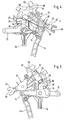
- a coupling device 10 is shown, the between the door handles (not shown) and the pawl (also not shown) of a door lock, in particular a motor vehicle door or flap is switched and the various locking functions required.
- the coupling device 10 has a first connecting lever 12, which is connected to the inside door handle, a second connecting lever 14, which with the outside door handle communicates, and a driver lever 16, which with a Pawl (not shown) cooperates and this in If it pivots, it opens.
- the pawl and the Driver levers can also be formed in one piece.
- the two connecting elements 12, 14 and the driver element 16 each consist of sheet metal one for the transfer of the required Forces suitable strength and are about a common, axis pivotally supported by a pin 18.
- return springs 20, 22, 24 provided around the two connecting levers 12, 14 and the driving lever To secure 16 in their rest position.
- the two connecting elements 12, 14 and the driver element 16 are designed such that between themselves there is no positive connection.
- This form fit for transmission the operating forces from the door handles to the pawl is by a coupling element 26 with a bolt-like Projection 28 accessible, the radial in an intermediate space 30 is movable by a first driving flank 32 of the first Connecting lever 12 and a second driving flank 34 of the second connecting lever 14 on one side and one Following flank 36 of the driving lever 16 on the other side is limited.
- the first driving flank 32 has the smallest the second driving flank 34 is a middle flank and the following flank 36 the largest radial extension.
- a retaining spring 38 which is connected to the coupling element 26 via a pin 40 acts, strives to do this in its radially innermost position to hold, in which the bolt-like projection 28, the Length of course over the depth of the two connecting elements 12, 14 and the driver element 16 is sufficient positive connection between the two connecting levers 12, 14 and the driver lever 16. In this is the first position of the coupling element 26 Door lock unlocked through the existing form closure Position.
- the coupling device 10 also has a first one Actuation lever 42 and a second actuation lever 44, which is common around a defined by a further bolt 46 Are pivotable.
- the bolt 46, the on the lever 42 can be molded or welded offers also the retaining spring 38 of the coupling element 26 stop.
- On one Lever arm 48 of the first actuating lever 42 is in one area covering the coupling element 26 in the circumferential direction about the axis of rotation of the first actuating lever 42 formed elongated hole 50 is provided, in which a pin 52 connected to coupling element 26 projects (see FIG. 2).
- the unlocked door lock position shown in FIGS. 1 and 2 is also the operating lever 42 in its rest position and the pin 52 is in plant or near the end of the space 30 facing Slot 50.
- a claw 56 is formed, in which a driver element a preferably electrically driven central locking drive intervenes.
- a driver element a preferably electrically driven central locking drive intervenes.
- the second actuating lever 44 serves the coupling element 26 and thus the bolt-like projection 28 in one middle radial position (see Fig. 3) between the two to hold radial positions shown in Fig. 1 and Fig. 4.
- the second actuating lever 44 can be actuated via an actuating arm 58 for this purpose in the child lock position shown in FIG. 3 be pivoted, for example by a bistable Spring element is locked.
- This also makes a holding arm 60 of the second operating lever 44 in one of the axis of rotation the two connecting levers 12, 14 are pivoted further away, one cooperating with a child safety bolt 62 Contact edge (not visible) ensures that the coupling element is not in its when the door lock is unlocked radially innermost position, as shown in FIGS.
- the retaining spring 38 also ensures a storage function of Closed positions. For example, there is the coupling element in the radially outer shown in Figs. 4 and 5 Position and is subsequently pulled, for example Outside door handle unlocks the door lock, d. H. the first Operating lever 42 in the position shown in Figs. 1 and 2 pivoted, the coupling member 26 because of the second driver flank 34 not blocked space 30 get into its radially inner position. The swivel movement of the first operating lever 42 is sufficient, however long trained slot 50 does not hinder, wherein the pin 52 of the blocked coupling element 26 accordingly moved in the slot 50.
- Another conceivable function that in the illustrated embodiment is not implemented concerns a security ejection, who unlocked the door lock Allow actuation of the inside door handle when locked should.
- a suitable operative connection between the first link lever 12 and the first operating lever 42 can be provided with the childproof lock switched on even without opening the pawl immediately for switching the door lock to the unlocked state can worry, so that a subsequent opening of the door from the outside or, with the childproof lock switched off, from the inside and outside is possible.
Landscapes
- Health & Medical Sciences (AREA)
- Child & Adolescent Psychology (AREA)
- Lock And Its Accessories (AREA)
Abstract
Description
Bei dieser Bauform lassen sich die auftretenden Kräfte bei sehr geringem Bauraum gut beherrschen und die Reibungsverluste in dem Umlenkmechanismus sind besonders gering.
- Fig. 1
- eine Kupplungsvorrichtung eines Türschlosses im Entriegelungszustand;
- Fig. 2
- eine Rückansicht der Kupplungsvorrichtung gemäß Fig. 1;
- Fig. 3
- eine Frontansicht der Kupplungsvorrichtung gemäß Fig. 1 bei in der Stellung "Kindersicherung" befindlichem Türschloß;
- Fig. 4
- eine Ansicht der Kupplungsvorrichtung gemäß Fig. 1 bei verriegeltem Türschloß;
- Fig. 5
- eine Rückansicht der Kupplungsvorrichtung in der Stellung gemäß Fig. 4.
Claims (15)
- Kupplungsvorrichtung für Türverriegelungsanlagen zur formschlüssigen Übertragung von Betätigungskräften von wenigstens zwei Türgriffen auf eine Schloßfalle eines Türschlosses, wobei jeweils ein Verbindungselement (12, 14) für einen Türaußengriff bzw. Türinnengriff, ein Mitnehmerelement (16) zur Verbindung mit der Schloßfalle und ein Kupplungselement (26, 28) vorgesehen ist, das in eine erste Stellung, in welcher es den Formschluß zwischen den beiden Verbindungselementen (12, 14) und dem Mitnehmerelement (16) herstellt, und in eine zweite Stellung bewegbar ist, in welcher der Formschluß zwischen den Verbindungselementen (12, 14) und dem Mitnehmerelement (16) aufgehoben ist, dadurch gekennzeichnet, daß das Kupplungselement (26, 28) in eine dritte Stellung bewegbar ist, in welcher nur das Verbindungselement (14) eines Türgriffes formschlüssig mit dem Mitnehmerelement (16) zusammenwirkt, während der Verbindungshebel (12) des anderen Türgriffes von dem Mitnehmerelement (16) entkoppelt ist.
- Kupplungsvorrichtung nach Anspruch 1, dadurch gekennzeichnet, daß der Türaußengriff über sein Verbindungselement (14) in der dritten Stellung formschlüssig mit dem Mitnehmerelement (16) verbunden ist.
- Kupplungsvorrichtung nach Anspruch 1 oder 2, dadurch gekennzeichnet, daß die Verbindungselemente (12, 14) und das Mitnehmerelement (16) drehbar auf einer Achse gelagert sind und das Kupplungselement (26, 28) im wesentlichen radial zwischen seinen Stellungen bewegbar ist.
- Kupplungsvorrichtung nach einem der vorhergehenden Ansprüche, dadurch gekennzeichnet, daß die Verbindungselemente (12, 14) und das Mitnehmerelement (16) aus Blech bestehen und geschichtet angeordnet sind.
- Kupplungsvorrichtung nach Anspruch 3 oder 4, dadurch gekennzeichnet, daß das Kupplungselement (26) ein bolzenähnliches Element (28) aufweist, das in einem radialen Freiraum (30) zwischen den Verbindungselementen (12, 14, 32, 34) und dem Mitnehmerelement (16, 36) bewegbar ist, wobei ein Verbindungselement (12) einen sich radial bis in den Bereich der ersten Stellung des bolzenähnlichen Elements (28) erstreckenden Mitnehmer (32) und das andere Verbindungselement (14) einen sich bis in den Bereich der dritten Stellung des bolzenähnlichen Elements (28) erstreckenden Mitnehmer (34) aufweist.
- Kupplungsvorrichtung nach einem der vorhergehenden Ansprüche, dadurch gekennzeichnet, daß das Kupplungselement (26) mit Hilfe eines Federelements (38) in Richtung seiner ersten Stellung vorbelastet ist, wobei bei freigegebenem Kupplungselement (26) eine Bewegung aus der zweiten Stellung über die mittlere dritte Stellung in die erste Stellung erfolgt.
- Kupplungsvorrichtung nach einem der vorhergehenden Ansprüche, dadurch gekennzeichnet, daß zwei separate Betätigungselemente (42, 44) vorgesehen sind, wobei ein erstes Betätigungselement (42) zum Bewegen des Kupplungselements (26) zwischen der ersten und der zweiten Stellung und das zweite Betätigungselement (44) zum Bewegen des Kupplungselements in die dritte Stellung bzw. Halten in der dritten Stellung vorgesehen ist.
- Kupplungsvorrichtung nach einem der vorhergehenden Ansprüche, dadurch gekennzeichnet, daß wenigstens ein Betätigungselement (42, 44) für das Kupplungselement (26) mit Spiel versehen ist, das dem Kupplungselement eine bestimmte Relativbewegung zu dem wenigstens einen Betätigungselement (42, 44) ermöglicht.
- Kupplungsvorrichtung nach Anspruch 7 oder 8, dadurch gekennzeichnet, daß die Betätigungselemente (42, 44) aus Blech gefertigt sind.
- Kupplungsvorrichtung nach einem der Ansprüche 7 bis 9, dadurch gekennzeichnet, daß die beiden Betätigungselemente (42, 44) um eine gemeinsame Schwenkachse verstellbar sind.
- Kupplungsvorrichtung nach einem der Ansprüche 7 bis 10, dadurch gekennzeichnet, daß wenigstens ein Betätigungselement (42, 44) motorisch angetrieben ist.
- Kupplungsvorrichtung nach Anspruch 11, dadurch gekennzeichnet, daß der erste Betätigungshebel (42) über einen elektrischen oder pneumatischen Antrieb verfügt.
- Kupplungsvorrichtung nach einem der Ansprüche 7 bis 12, dadurch gekennzeichnet, daß das Kupplungselement (26) über wenigstens ein stiftähnliches Element (52, 62) verfügt, so daß eine Mitnahme durch die beiden Betätigungselemente (42, 44) ermöglicht ist.
- Kupplungsvorrichtung nach Anspruch 13, dadurch gekennzeichnet, daß wenigstens ein Stiftelement (52) des Kupplungselements (26) in einem Langloch (50) eines Betätigungselements (42) sitzt.
- Kupplungsvorrichtung nach einem der Ansprüche 7 bis 14, dadurch gekennzeichnet, daß ein Sicherungsauswurf vorgesehen ist, der aus einer Wirkverbindung zwischen dem Verbindungselement (12) des Türinnengriffes und dem ersten Betätigungselement besteht.
Applications Claiming Priority (2)
| Application Number | Priority Date | Filing Date | Title |
|---|---|---|---|
| DE10046731A DE10046731A1 (de) | 2000-09-21 | 2000-09-21 | Kupplungsvorrichtung für Türverriegelungsanlagen |
| DE10046731 | 2000-09-21 |
Publications (2)
| Publication Number | Publication Date |
|---|---|
| EP1191171A2 true EP1191171A2 (de) | 2002-03-27 |
| EP1191171A3 EP1191171A3 (de) | 2003-11-12 |
Family
ID=7657056
Family Applications (1)
| Application Number | Title | Priority Date | Filing Date |
|---|---|---|---|
| EP01122311A Withdrawn EP1191171A3 (de) | 2000-09-21 | 2001-09-18 | Kupplungsvorrichtung für Türverriegelungsanlagen |
Country Status (3)
| Country | Link |
|---|---|
| US (1) | US20020050720A1 (de) |
| EP (1) | EP1191171A3 (de) |
| DE (1) | DE10046731A1 (de) |
Cited By (1)
| Publication number | Priority date | Publication date | Assignee | Title |
|---|---|---|---|---|
| EP1770233A3 (de) * | 2005-09-30 | 2010-04-21 | Aisin Seiki Kabushiki Kaisha | Kraftfahrzeugtürschloss |
Families Citing this family (6)
| Publication number | Priority date | Publication date | Assignee | Title |
|---|---|---|---|---|
| DE10320448A1 (de) * | 2003-05-08 | 2004-12-16 | Kiekert Ag | Kraftfahrzeugtürverschluss |
| DE10331622A1 (de) * | 2003-07-12 | 2005-02-03 | Happich Fahrzeug- Und Industrieteile Gmbh | Verschlussvorrichtung |
| KR100957102B1 (ko) * | 2008-06-25 | 2010-05-13 | 현대자동차주식회사 | 차량용 도어래치기구 |
| US8376424B2 (en) | 2010-09-27 | 2013-02-19 | Ford Global Technologies | Door handle assembly for automotive vehicle |
| DE102011120188B4 (de) * | 2011-12-05 | 2013-08-29 | Audi Ag | Notentriegelungseinrichtung für einenFahrzeug-Kofferraum |
| JP6697367B2 (ja) | 2016-10-25 | 2020-05-20 | 三井金属アクト株式会社 | ドアロック装置 |
Family Cites Families (13)
| Publication number | Priority date | Publication date | Assignee | Title |
|---|---|---|---|---|
| CA1326502C (en) * | 1988-03-11 | 1994-01-25 | Wolfgang Thau | Latch mechanism, components thereof and process of manufacture for components thereof |
| DE8915994U1 (de) * | 1988-08-13 | 1992-11-05 | Bayerische Motoren Werke AG, 8000 München | Kraftfahrzeugtürverschluß mit einem Zentralverriegelungsantrieb |
| DE3908183C5 (de) * | 1989-03-14 | 2005-01-05 | Kiekert Ag | Kraftfahrzeug-Türverschluß |
| DE4036513A1 (de) * | 1989-12-16 | 1991-06-20 | Bocklenberg & Motte Bomoro | Kraftfahrzeug-tuerschloss, haubenschloss oder dergleichen |
| DE4222868A1 (de) * | 1992-07-11 | 1994-01-13 | Bosch Gmbh Robert | Sperrvorrichtung für Türen eines Kraftfahrzeugs |
| DE4313248C3 (de) * | 1993-04-23 | 2003-02-13 | Bosch Gmbh Robert | Kraftfahrzeug-Türschloß |
| FR2710677B1 (fr) * | 1993-09-28 | 1996-03-08 | Ymos France | Serrure pour porte de véhicule automobile. |
| DE19631869A1 (de) * | 1996-08-07 | 1998-02-12 | Bosch Gmbh Robert | Kraftfahrzeug-Türschloß oder dergleichen |
| DE19635414C2 (de) * | 1996-08-31 | 2001-07-12 | Mannesmann Vdo Ag | Schloß, insbesondere für Fahrzeugtüren oder dergleichen |
| DE19636464A1 (de) * | 1996-09-07 | 1998-03-12 | Mannesmann Vdo Ag | Schließeinrichtung, insbesondere für Fahrzeugtüren oder dergleichen |
| DE19702420C5 (de) * | 1997-01-24 | 2009-12-31 | Audi Ag | Steuervorrichtung für einen Verschluß, insbesondere von Kraftfahrzeugtüren |
| DE19806154C2 (de) * | 1998-01-20 | 2000-11-02 | Kiekert Ag | Kraftfahrzeugtürverschluß |
| GB9809640D0 (en) * | 1998-05-06 | 1998-07-01 | Meritor Light Vehicle Sys Ltd | Latch mechanism |
-
2000
- 2000-09-21 DE DE10046731A patent/DE10046731A1/de not_active Withdrawn
-
2001
- 2001-09-18 EP EP01122311A patent/EP1191171A3/de not_active Withdrawn
- 2001-09-19 US US09/957,675 patent/US20020050720A1/en not_active Abandoned
Cited By (2)
| Publication number | Priority date | Publication date | Assignee | Title |
|---|---|---|---|---|
| EP1770233A3 (de) * | 2005-09-30 | 2010-04-21 | Aisin Seiki Kabushiki Kaisha | Kraftfahrzeugtürschloss |
| US7798539B2 (en) | 2005-09-30 | 2010-09-21 | Aisin Seiki Kabushiki Kaisha | Door lock device for vehicle |
Also Published As
| Publication number | Publication date |
|---|---|
| DE10046731A1 (de) | 2002-04-11 |
| EP1191171A3 (de) | 2003-11-12 |
| US20020050720A1 (en) | 2002-05-02 |
Similar Documents
| Publication | Publication Date | Title |
|---|---|---|
| EP0722029B1 (de) | Kraftfahrzeug-Türschloss mit rotorischer Zentralverriegelung | |
| EP2916045A1 (de) | Parksperrenanordnung und Kraftfahrzeuggetriebe | |
| EP1394345A2 (de) | Kraftfahrzeugschloss | |
| DE102016109326A1 (de) | System mit Kraftfahrzeugschließvorrichtungen | |
| DE102021128302A1 (de) | Elektrisch betätigbares Kraftfahrzeugschloss mit Doppelhubfunktion | |
| EP4555163A1 (de) | Kraftfahrzeugschloss insbesondere kraftfahrzeug-türschloss | |
| DE10046731A1 (de) | Kupplungsvorrichtung für Türverriegelungsanlagen | |
| EP1617019B1 (de) | Elektromechanisches Türschloss | |
| EP4585778A1 (de) | Schloss | |
| DE60121495T2 (de) | Verriegelungsvorrichtung | |
| EP1617018B1 (de) | Elektromechanisches Türschloss | |
| DE102017108752A1 (de) | Schloss mit Zuzieheinrichtung für ein Kraftfahrzeug | |
| DE10339542B4 (de) | Kraftfahrzeugtürverschluss | |
| EP1947275B1 (de) | Schloss | |
| DE102023112035A1 (de) | Kraftfahrzeug-Schloss | |
| EP3899174B1 (de) | Schloss für ein kraftfahrzeug | |
| EP0942123A1 (de) | Vorrichtung zum Verriegeln einer Abdeckung nach Art einer Karosseriehaube eines Kraftfahrzeugs | |
| EP3438384A1 (de) | Schloss | |
| EP0826856B1 (de) | Kopplungseinrichtung für ein Schloss, insbesondere ein Türschloss eines Kraftfahrzeuges | |
| DE102005000078A1 (de) | Schloss | |
| EP1806468B1 (de) | Elektromechanisches Türschloss | |
| DE102019125947A1 (de) | Notbetätigungsvorrichtung zum manuellen öffnen einer fahrzeugtür | |
| DE69806080T2 (de) | Türschloss für Kraftfahrzeuge | |
| DE102024113350A1 (de) | Doppelhub-Schließsystem mit schneller Wiederfreigabe | |
| DE10002732C2 (de) | Türschloß mit Sicherungsauswurf |
Legal Events
| Date | Code | Title | Description |
|---|---|---|---|
| PUAI | Public reference made under article 153(3) epc to a published international application that has entered the european phase |
Free format text: ORIGINAL CODE: 0009012 |
|
| AK | Designated contracting states |
Kind code of ref document: A2 Designated state(s): AT BE CH CY DE DK ES FI FR GB GR IE IT LI LU MC NL PT SE TR |
|
| AX | Request for extension of the european patent |
Free format text: AL;LT;LV;MK;RO;SI |
|
| PUAL | Search report despatched |
Free format text: ORIGINAL CODE: 0009013 |
|
| AK | Designated contracting states |
Kind code of ref document: A3 Designated state(s): AT BE CH CY DE DK ES FI FR GB GR IE IT LI LU MC NL PT SE TR |
|
| AX | Request for extension of the european patent |
Extension state: AL LT LV MK RO SI |
|
| AKX | Designation fees paid |
Designated state(s): DE ES FR GB IT |
|
| STAA | Information on the status of an ep patent application or granted ep patent |
Free format text: STATUS: THE APPLICATION IS DEEMED TO BE WITHDRAWN |
|
| 18D | Application deemed to be withdrawn |
Effective date: 20040401 |