EP1189789B1 - Schliesssytem, insbesondere für ein kraftfahrzeug - Google Patents
Schliesssytem, insbesondere für ein kraftfahrzeug Download PDFInfo
- Publication number
- EP1189789B1 EP1189789B1 EP00945652A EP00945652A EP1189789B1 EP 1189789 B1 EP1189789 B1 EP 1189789B1 EP 00945652 A EP00945652 A EP 00945652A EP 00945652 A EP00945652 A EP 00945652A EP 1189789 B1 EP1189789 B1 EP 1189789B1
- Authority
- EP
- European Patent Office
- Prior art keywords
- range
- signal
- key
- control device
- transmitted
- Prior art date
- Legal status (The legal status is an assumption and is not a legal conclusion. Google has not performed a legal analysis and makes no representation as to the accuracy of the status listed.)
- Expired - Lifetime
Links
- 238000005259 measurement Methods 0.000 claims description 41
- 238000011156 evaluation Methods 0.000 claims description 6
- 238000001208 nuclear magnetic resonance pulse sequence Methods 0.000 claims description 6
- 230000010363 phase shift Effects 0.000 claims 1
- 230000008901 benefit Effects 0.000 description 3
- 230000005540 biological transmission Effects 0.000 description 2
- 238000010586 diagram Methods 0.000 description 2
- 230000007613 environmental effect Effects 0.000 description 2
- 238000012545 processing Methods 0.000 description 2
- 230000001960 triggered effect Effects 0.000 description 2
- 238000013475 authorization Methods 0.000 description 1
- 230000000052 comparative effect Effects 0.000 description 1
- 230000001419 dependent effect Effects 0.000 description 1
- 238000011161 development Methods 0.000 description 1
- 230000018109 developmental process Effects 0.000 description 1
- 230000007717 exclusion Effects 0.000 description 1
- 239000004615 ingredient Substances 0.000 description 1
- 230000007257 malfunction Effects 0.000 description 1
- 238000005457 optimization Methods 0.000 description 1
- 238000012549 training Methods 0.000 description 1
- 238000012546 transfer Methods 0.000 description 1
Images


Classifications
-
- B—PERFORMING OPERATIONS; TRANSPORTING
- B60—VEHICLES IN GENERAL
- B60R—VEHICLES, VEHICLE FITTINGS, OR VEHICLE PARTS, NOT OTHERWISE PROVIDED FOR
- B60R25/00—Fittings or systems for preventing or indicating unauthorised use or theft of vehicles
- B60R25/20—Means to switch the anti-theft system on or off
- B60R25/24—Means to switch the anti-theft system on or off using electronic identifiers containing a code not memorised by the user
-
- G—PHYSICS
- G07—CHECKING-DEVICES
- G07C—TIME OR ATTENDANCE REGISTERS; REGISTERING OR INDICATING THE WORKING OF MACHINES; GENERATING RANDOM NUMBERS; VOTING OR LOTTERY APPARATUS; ARRANGEMENTS, SYSTEMS OR APPARATUS FOR CHECKING NOT PROVIDED FOR ELSEWHERE
- G07C9/00—Individual registration on entry or exit
- G07C9/00174—Electronically operated locks; Circuits therefor; Nonmechanical keys therefor, e.g. passive or active electrical keys or other data carriers without mechanical keys
- G07C9/00309—Electronically operated locks; Circuits therefor; Nonmechanical keys therefor, e.g. passive or active electrical keys or other data carriers without mechanical keys operated with bidirectional data transmission between data carrier and locks
-
- G—PHYSICS
- G07—CHECKING-DEVICES
- G07C—TIME OR ATTENDANCE REGISTERS; REGISTERING OR INDICATING THE WORKING OF MACHINES; GENERATING RANDOM NUMBERS; VOTING OR LOTTERY APPARATUS; ARRANGEMENTS, SYSTEMS OR APPARATUS FOR CHECKING NOT PROVIDED FOR ELSEWHERE
- G07C9/00—Individual registration on entry or exit
- G07C9/00174—Electronically operated locks; Circuits therefor; Nonmechanical keys therefor, e.g. passive or active electrical keys or other data carriers without mechanical keys
- G07C9/00309—Electronically operated locks; Circuits therefor; Nonmechanical keys therefor, e.g. passive or active electrical keys or other data carriers without mechanical keys operated with bidirectional data transmission between data carrier and locks
- G07C2009/00555—Electronically operated locks; Circuits therefor; Nonmechanical keys therefor, e.g. passive or active electrical keys or other data carriers without mechanical keys operated with bidirectional data transmission between data carrier and locks comprising means to detect or avoid relay attacks
-
- G—PHYSICS
- G07—CHECKING-DEVICES
- G07C—TIME OR ATTENDANCE REGISTERS; REGISTERING OR INDICATING THE WORKING OF MACHINES; GENERATING RANDOM NUMBERS; VOTING OR LOTTERY APPARATUS; ARRANGEMENTS, SYSTEMS OR APPARATUS FOR CHECKING NOT PROVIDED FOR ELSEWHERE
- G07C9/00—Individual registration on entry or exit
- G07C9/00174—Electronically operated locks; Circuits therefor; Nonmechanical keys therefor, e.g. passive or active electrical keys or other data carriers without mechanical keys
- G07C2009/00753—Electronically operated locks; Circuits therefor; Nonmechanical keys therefor, e.g. passive or active electrical keys or other data carriers without mechanical keys operated by active electrical keys
- G07C2009/00769—Electronically operated locks; Circuits therefor; Nonmechanical keys therefor, e.g. passive or active electrical keys or other data carriers without mechanical keys operated by active electrical keys with data transmission performed by wireless means
- G07C2009/00793—Electronically operated locks; Circuits therefor; Nonmechanical keys therefor, e.g. passive or active electrical keys or other data carriers without mechanical keys operated by active electrical keys with data transmission performed by wireless means by Hertzian waves
-
- G—PHYSICS
- G07—CHECKING-DEVICES
- G07C—TIME OR ATTENDANCE REGISTERS; REGISTERING OR INDICATING THE WORKING OF MACHINES; GENERATING RANDOM NUMBERS; VOTING OR LOTTERY APPARATUS; ARRANGEMENTS, SYSTEMS OR APPARATUS FOR CHECKING NOT PROVIDED FOR ELSEWHERE
- G07C2209/00—Indexing scheme relating to groups G07C9/00 - G07C9/38
- G07C2209/60—Indexing scheme relating to groups G07C9/00174 - G07C9/00944
- G07C2209/63—Comprising locating means for detecting the position of the data carrier, i.e. within the vehicle or within a certain distance from the vehicle
Definitions
- the invention relates to a locking system according to the preamble of claim 1
- Enclosing system is known from EP 0 673 003 A1. Further locking systems are known from DE 43 40 260 A1 known.
- the locking system consists of at least two States owning control device for unlocking and / or Locking the car doors, the ignition, the Steering wheel lock o. The like., And an associated electronic key.
- the control device and the Keys have means for their intended operation for sending and / or receiving signals. in the Intended operation is between the key and the Control device at least one signal as coded Operating signal transferable, so that after positive evaluation the transmitted operating signal and thus legitimate Key a change in the state of the controller is feasible.
- Such locking systems are also known as "keyless Entry / Go functionality evolves, with a manual operation of the electronic key by the User is no longer necessary. It is enough that the User carries the key with him, with the Operating signal between the controller and the Key is automatically transferred when the user in, near and / or inside the motor vehicle resides active range.
- a locking system for a motor vehicle in which one of a user portable key card with a control device in the Motor vehicle communicates via radio signals. Also with this Locking system can be the distance between the key card and the motor vehicle by means of the duration of a radio wave be measured. This will change the position of the key card determined within a predetermined range. The Authorization to trigger an action of the locking system will then be checked if the key card is in the right one Is located area. Also this known locking system has the above-mentioned disadvantages.
- the invention is based on EP 0 673 003 A1 Task underlying the theft security of the locking system even further to improve.
- the invention is based on the idea that one of the Both facilities of the locking system, namely of the Control device in the vehicle and / or the key, a Range signal is sent.
- the range signal is after reception in the other facility substantially at the same time sent back from this. For this is the acting as a mirror for the range signal Return device in the manner of a transverter educated.
- the received with the transmitted range signal by means of a Comparison device for determining the distance between the two Facilities evaluated. Since no processing of Range signal in the other device takes place but the other device in the way of a mirror acts, can tolerances in the components of the key and / or the controller does not even affect. This results in the correct double runtime between the control device and the key or the distance traveled of the range signal.
- the comparator is one Phase comparator, in which the phase angle of the emitted signal with that of the returned Signal is compared.
- the evaluation of the phase offset For example, by means of a processor, logic o. The like., finally yields twice the duration and / or the distance traveled of the range signal.
- Range signals emitted by the one device
- the individual range signals follow one after the other by a specific pulse sequence for the range signals is strung together.
- the individual range signals can also with intervals follow each other by other signals, such as Parts of the operating signal to be transmitted in the intervals. Conveniently, then the mean of the Single measurements are calculated for distance determination, so that Distance measurement errors are minimized.
- certain Single measurements from the several single measurements of the Range are manipulated so that these education of the mean value are not used.
- the database, which of the individual measurements in this way are manupulated, are the same for both institutions or be the same way in both facilities determined and / or calculated. By this measure, the Manipulation security for distance determination continues elevated.
- an optimization with regard to Manipulation security of the range measurement can be continue by sprinkling a defined number of Range limitation measurements in the whole Data protocol that exists between the two facilities as Signal is transmitted. Appropriately, you will any or permanent change in the location of this Make measurements so that the respective measurement for a Manipulator is unpredictable. To mark for the Making a range measurement can do that Range signal emitting device in one for it switch operating mode provided, the switching the other facility within the data log for the transmitted signal is communicated. Finally, one leads Variation of the pulse sequence of the range measurement to a Exclusion of the ambiguity of the measurement results.
- the electrical and / or electronic components o. The like. may have tolerances, for example, too different delay times in the Signal processing can lead.
- Such system tolerances of Both devices can be in a calibration before the actual measurement sequence for distance determination determine. Subsequently, these system tolerances can then considered accordingly during the actual measurement whose consideration in the Comparative device offers. For example, the determined tolerance values of the through the components and the Air gap caused total running time of the range signal then be subtracted.
- the advantages achieved by the invention are In particular, that an unauthorized operation of the Locking system is detected with certainty and therefore can also effectively prevent. Just as well will be effective Protection against manipulation of the locking system, in particular against attacks by means of transparent electronics unauthorized persons. Besides, they are Incorrect operation of the locking system excluded.
- the locking system according to the invention therefore increases the Theft security continues.
- Another advantage is the fact that a limitation the range of the effective range for the locking system is given outside the motor vehicle. At the Keyless Entry / Go functionality is for security reasons required that the effective range to the immediate vicinity of the motor vehicle is limited. Owing to Environmental conditions, tolerances in the locking system itself, Inaccurate settings of the locking system o. The like. Can however, overreaches occur. Such overreaches can be with the help of the locking system of the invention limit effective values to acceptable levels without further effort.
- the motor vehicle 1 is with a Locking system 3 provided as a door closing system, the one as a control device 4 formed first device and one as an associated electronic key 5 trained second device includes.
- the electronic Key 5 is in the possession of the authorized User 2, whereby this within an effective range 8 Access to the motor vehicle 1 has.
- the control device 4 has at least two states, wherein in the first state, a lock and in the second Condition unlocking the car doors 6 is present.
- the Control device 4 and the key 5 have to their Proper operation means for sending and / or Receiving signals. At least one of these between the key 5 and the control device 4 transmitted Signals are an encoded operating signal 7.
- the transmitted operating signal 7 is a change of State of the control device 4 effected.
- the transfer the coded operating signal 7 can automatically without Participation of the user 2 take place as soon as this Effective range 8 enters. This will unlock the Car doors 6 according to the keyless entry functionality triggered. If the user leaves the effective range 8, then takes place an automatic locking of the car doors. 6
- Fig. 1 a situation is further shown, in which two unauthorized persons 9, 10 Access to the vehicle 1 after the authorized user 2 'wants to Effective range 8 has left.
- This is the first Person 9 with a prepared electronic key 11 near the motor vehicle 1, while the second Person 10 with a prepared control device 12 in the Near the authorized user 2 'stops, the prepared keys 11 and the prepared Controller 12, of course, the coded Do not know the operating signal 7.
- the prepared Control device 12 is the authorized user 2 ' worn key 5 is activated, so that a transmission of Operating signals 13 between the prepared Control device 12 and the key 5 takes place.
- the Operating signals 13 are now, if appropriate accordingly amplified, between the prepared controller 12 and the control device 4 in the motor vehicle 1 via the prepared key 11 forwarded so that the Change of state of the control device 4 takes place without this would be perceived by the user 2 '.
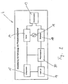
- the Control device 4 as means for sending one with a Oscillator 18 connected transmitter 16 for transmitting a Signal via an antenna system 19.
- the Control device 4 contains the Control device 4, a microprocessor 14 and a Logic circuit and a code generator 15, so that the from Transmitter 16 transmitted signal may optionally be encoded.
- One received by the key 5 via the antenna system 19 Signal is supplied to a receiver 17, wherein the Antenna system 19 and the receiver 17, the means for Receive form, and evaluated in the microprocessor 14.
- the key 5 also has one of an oscillator 24 and an antenna system 21 formed means for sending.
- Antenna system 19 also includes a part of the means for receiving in the key 5, but the other ingredients, such as Receiver, microprocessor o. The like., Not shown here are.
- signals that are coded Operating signal 7 can act by means of electromagnetic Waves transmitted.
- the means for sending and receiving in the control device 4 as well as in the key 5 are in addition for the Range measurement, i. for the determination of the distance between the control device 4 and the key 5, used by sending these as well as receiving a Range signal are suitable. Further includes the agent for determining distance, a shown in Fig. 2 Comparator for the sent and the received Range signal that is in one of the two facilities, and Although present in the control device 4 is located.
- the comparison device in the control device 4 is preferably designed as a phase comparator 20.
- the Phase comparator 20 is a determination of the phase position for the transmitted and received range signal, wherein a Phase offset in the phase comparator 20 results. From the Phase offset, in turn, the microprocessor 14 the double transit time between the controller 4 and the Determine key 5 for the range signal. Furthermore will not give you more details on this previously published German patent application DE 199 41 428 A1 of the applicant.
- Return device 22 located in the other of the two Facilities, in the present case in the key 5, is located.
- the return device 22 passes over the Antenna system 21 received range signal immediately back to the antenna system 21. If necessary, can still an implementation of the range signal in the key 5 via an amplifier 23. If desired, this can Signal or its code in the return device 22 yet changed by means of the oscillator 24 and a mixer 25 become. It is essential, however, that no further evaluation the signal takes place in the logic of the key 5 and the Returning device 22 together with the antenna system 21 in the Type of transverter works by the transverter like a mirror for that sent from the controller 4 Range signal acts.
- FIGS. 2 and 3 The operation of the control device 4 and the key. 5 for determining the distance is shown in FIGS. 2 and 3 now as follows. From one device, namely from the Control device 4 is a signal in the manner of a adjustable code sequence as range signal over the Antenna system 19 sent.
- the code sequence contains at least a transmit pulse, but can also be from a whole sequence consist of transmit pulses. That of the control device 4th sent range signal is then from the other Device, in the present case by means of the antenna system 21 of the key 5 received.
- the received Range signal is fed to the return device 22, implemented directly in the return device 22 and almost simultaneously returned to the antenna system 21. from Antenna system 21 in key 5 becomes the range signal essentially at the same time as the one institution, namely sent back to the control device 4.
- the control device 4 in the control device 4, takes place then the comparison between the sent and the received range signal by the phase offset of the transmitted and returned range signal to Runtime determination is evaluated in the phase comparator 20. If the determined distance is permissible, with which the key 5 within the effective range 8 shown in FIG. 1 is, then is after positive evaluation of the transmitted Operation signal 7, a state change of the control device 4 feasible. Is the determined distance, however inadmissible, whereby the key 5 is not in the effective range 8 is located, so even with a legitimate key 5 no change of state of the control device 4.
- Range signals to each other with or without distance following by the control device 4 are sent out. Conveniently, it offers one behind the other following sequence of a specific pulse sequence. Then then the mean of these Individual measurements are formed. This will make several Single measurements of the range carried out. As each Single measurement is subject to a measurement error can be at several individual measurements a statistical minimization of the Achieve distance measurement error. To the Tamperproof for the distance determination continues to can increase certain individual measurements from the series of several individual measurements to form the mean value not be used.
- Range signals in a defined number for Single measurements of the range be scattered. It offers It is about, any change in the location of this Range signals in the data log, causing the Security against unauthorized manipulation of the locking system 3 is also further increased.
- the Range signal emitting control device 4 in a switchover to the intended operating mode.
- the Switching is key 5 within the data protocol notified for the transmitted signal. Receives the key 5 Now a corresponding data protocol, it will immediate return of the range signal in the key 5 triggered.
- the distance determination by means of the range signal between the two devices 4 and 5 protects the Locking system 3 not only against manipulation unauthorized persons 9, 10, but also has one further benefits. This is that a possibly occurring overreach of the locking system 3 automatically limited in the outer area of the motor vehicle 1 becomes. As a result, otherwise possible Malfunction of the locking system 3 with security prevented.
- the invention is not on the described and illustrated embodiment limited. Rather, it also includes all expert training within the scope of the inventive concept.
Landscapes
- Engineering & Computer Science (AREA)
- Mechanical Engineering (AREA)
- Computer Networks & Wireless Communication (AREA)
- Physics & Mathematics (AREA)
- General Physics & Mathematics (AREA)
- Lock And Its Accessories (AREA)
Description
- Fig. 1
- ein mit einem Schließsystem ausgestattetes Kraftfahrzeug,
- Fig. 2
- ein Blockschaltbild für die Steuereinrichtung im Kraftfahrzeug und
- Fig. 3
- ein Blockschaltbild für den Schlüssel.
- 1:
- Kraftfahrzeug
- 2,2':
- (berechtigter) Benutzer
- 3:
- Schließsystem
- 4:
- Steuereinrichtung / erste Einrichtung
- 5:
- elektronischer Schlüssel / zweite Einrichtung
- 6:
- Autotüre
- 7:
- Betriebssignal
- 8:
- Wirkbereich
- 9,10:
- nichtberechtigter Benutzer
- 11:
- präparierter Schlüssel
- 12:
- präparierte Steuereinrichtung
- 13:
- Betriebssignal (Übertragung bei Nichtberechtigung)
- 14:
- Mikroprozessor
- 15:
- Codegenerator
- 16:
- Sender
- 17:
- Empfänger
- 18:
- Oszillator (in steuereinrichtung)
- 19:
- Antennensystem (in Steuereinrichtung)
- 20:
- Phasenvergleicher
- 21:
- Antennensysten (im Schlüssel)
- 22:
- Rücksendeeinrichtung
- 23:
- Verstärker
- 24:
- Oszillator (im schlüssel)
- 25:
- Mischer
Claims (8)
- Schließsystem, insbesondere für ein Kraftfahrzeug (1), mit einer wenigstens zwei Zustände besitzenden, als Steuereinrichtung (4) ausgebildeten ersten Einrichtung, wie einer Steuereinrichtung (4) zur Ent- und/oder Verriegelung der Autotüren (6), des Zündschlosses oder der Lenkradverriegelung, und mit einer zugehörigen, als elektronischen Schlüssel (5) ausgebildeten zweiten Einrichtung, wobei die Steuereinrichtung (4) und der Schlüssel (5) zu deren bestimmungsgemäßen Betrieb Mittel zum Senden und/oder Empfangen von Signalen besitzen, und wobei es sich insbesondere bei wenigstens einem der zwischen dem Schlüssel (5) und der Steuereinrichtung (4) übertragenen Signale um ein codiertes Betriebssignal (7) handelt, sowie mit einem Mittel zur Bestimmung des Abstandes zwischen dem Schlüssel (5) und der Steuereinrichtung (4), wobei von einer der beiden Einrichtungen (4, 5) ein Signal, das insbesondere wenigstens einen Sendepuls enthält, als Reichweitensignal gesendet wird, wobei in der anderen Einrichtung (5, 4) eine Rücksendeeinrichtung (22) für das Reichweitensignal befindlich ist, und wobei in wenigstens einer der beiden Einrichtungen (4, 5) sich eine Vergleichseinrichtung für das gesendete und das empfangene Reichweitensignal befindet, so daß nach positiver Auswertung des übertragenen Betriebssignals (7) bei berechtigtem Schlüssel (5) und zulässigem Abstand eine Änderung des Zustandes der Steuereinrichtung (4) bewirkbar ist, wobei die Rücksendeeinrichtung (22) in der Art eines Transverters ausgebildet ist, dadurch gekennzeichnet, daß der Transverter als Spiegel für das in der Art einer einstellbaren Codefolge ausgestaltete Reichweitensignal wirkt, derart daß das von der einen Einrichtung (4, 5) gesendete Reichweitensignal unmittelbar in der Rücksendeeinrichtung (22) der anderen Einrichtung (5, 4) umgesetzt und im wesentlichen zeitgleich zu der einen Einrichtung (4, 5) zurückgesendet wird und
daß es sich bei der Vergleichseinrichtung um einen Phasenvergleicher (20) zur Bestimmung der Phasenlage für das gesendete und empfangene Reichweitensignal handelt. - Schließsystem nach Anspruch 1, dadurch gekennzeichnet, daß ein Prozessor (14), eine Logikschaltung o. dgl. in wenigstens einer der beiden Einrichtungen (4, 5) aus dem Phasenversatz, der als Ergebnis im Phasenvergleicher (20) resultiert, die Reichweite als Abstand zwischen dem Schlüssel (5) und der Steuereinrichtung (4) ermittelt.
- Schließsystem nach Anspruch 1 oder 2, dadurch gekennzeichnet, daß mehrere Reichweitensignale einander folgend, insbesondere hintereinander durch Aneinanderreihung einer bestimmten Pulsfolge, ausgesendet werden, um mehrere Einzelmessungen der Reichweite durchzuführen, wobei vorzugsweise anschließend der Mittelwert der Einzelmessungen zur Minimierung der Entfernungs-Meßfehler gebildet wird.
- Schließsystem nach einem der Ansprüche 1 bis 3, dadurch gekennzeichnet, daß bestimmte Einzelmessungen aus den mehreren Einzelmessungen der Reichweite zur Bildung des Mittelwertes nicht herangezogen werden, derart daß die Manipulationssicherheit für die Bestimmung des Abstandes erhöht ist.
- Schließsystem nach einem der Ansprüche 1 bis 4, dadurch gekennzeichnet, daß in das gesamte Datenprotokoll, das zwischen den beiden Einrichtungen (4, 5) als Signal übertragen wird, Reichweitensignale in einer definierten Anzahl für Einzelmessungen der Reichweite eingestreut sind, wobei insbesondere eine beliebige Veränderung der Lage dieser Reichweitensignale im Datenprotokoll vorgenommen ist.
- Schließsystem nach einem der Ansprüche 1 bis 5, dadurch gekennzeichnet, daß die das Reichweitensignal aussendende Einrichtung (4, 5) in einen dafür vorgesehenen Betriebsmodus umschaltet, wobei das Umschalten der anderen Einrichtung (5, 4) innerhalb des Datenprotokolls für das übertragene Signal mitgeteilt wird.
- Schließsystem nach einem der Ansprüche 1 bis 6, dadurch gekennzeichnet, daß bei mehreren gesendeten Reichweitensignalen eine variation der Pulsfolge zur Ausschließung von Mehrdeutigkeiten erfolgt.
- Schließsystem nach einem der Ansprüche 1 bis 7, dadurch gekennzeichnet, daß Systemtoleranzen der beiden Einrichtungen (4, 5), wie Verzögerungszeiten in deren elektrischen und/oder elektronischen Bauteilen o. dgl., in einer vorhergehenden Kalibrierung ermittelt werden, und daß die Systemtoleranzen bei der Messung der Reichweite, insbesondere in der Vergleichseinrichtung, entsprechend berücksichtigt werden.
Applications Claiming Priority (3)
| Application Number | Priority Date | Filing Date | Title |
|---|---|---|---|
| DE19929017 | 1999-06-25 | ||
| DE19929017 | 1999-06-25 | ||
| PCT/DE2000/002054 WO2001000461A1 (de) | 1999-06-25 | 2000-06-23 | Schliesssytem, insbesondere für ein kraftfahrzeug |
Publications (2)
| Publication Number | Publication Date |
|---|---|
| EP1189789A1 EP1189789A1 (de) | 2002-03-27 |
| EP1189789B1 true EP1189789B1 (de) | 2003-08-27 |
Family
ID=7912421
Family Applications (1)
| Application Number | Title | Priority Date | Filing Date |
|---|---|---|---|
| EP00945652A Expired - Lifetime EP1189789B1 (de) | 1999-06-25 | 2000-06-23 | Schliesssytem, insbesondere für ein kraftfahrzeug |
Country Status (3)
| Country | Link |
|---|---|
| EP (1) | EP1189789B1 (de) |
| DE (2) | DE10029170A1 (de) |
| WO (1) | WO2001000461A1 (de) |
Families Citing this family (10)
| Publication number | Priority date | Publication date | Assignee | Title |
|---|---|---|---|---|
| EP1069265A3 (de) * | 1999-07-01 | 2004-01-21 | Siemens Aktiengesellschaft | Zugangskontrolleinrichtung sowie Zugangskontroll- und Fahrberechtigungseinrichtung |
| DE10114876A1 (de) * | 2001-03-26 | 2002-10-17 | Siemens Ag | Identifikationssystem zum Nachweis einer Berechtigung für den Zugang zu einem Objekt oder die Benutzung eines Objekts, insbesondere eines Kraftfahrzeugs |
| FR2862589A1 (fr) * | 2003-11-25 | 2005-05-27 | Baron Denis | Dispositif antivol notamment pour automobiles. |
| GB0404857D0 (en) * | 2004-03-04 | 2004-04-07 | Koninkl Philips Electronics Nv | Improvements in or relating to time-of-flight ranging systems |
| US7791457B2 (en) * | 2006-12-15 | 2010-09-07 | Lear Corporation | Method and apparatus for an anti-theft system against radio relay attack in passive keyless entry/start systems |
| DE102007041783B8 (de) | 2007-09-03 | 2009-07-23 | Continental Automotive Gmbh | Flexible Schlüsselortung für passive Zugangs- und Fahrberechtigungssysteme |
| US8335598B2 (en) | 2008-09-23 | 2012-12-18 | Lear Corporation | System and method for detecting radio frequency signals and controlling vehicle operations in response thereto |
| US9554286B2 (en) | 2011-12-02 | 2017-01-24 | Lear Corporation | Apparatus and method for detecting a location of a wireless device |
| DE102012018188A1 (de) * | 2012-09-10 | 2014-03-13 | Udo Hagemann | Gerät zum spurlosen Öffnen und Starten von Fahrzeugen für sogenannten "Keyless Go" oder "Keyless Entry" Systeme. Es verlängert mittels Funkübertragung die Reichweite des Keyless Fahrzeugschlüssels auf bis zu 500 Meter. |
| DE102013226840B4 (de) * | 2013-12-20 | 2019-07-11 | Continental Automotive Gmbh | Drahtlose Zugangsvorrichtung für ein Fahrzeug, insbesondere ein Kraftfahrzeug |
Family Cites Families (3)
| Publication number | Priority date | Publication date | Assignee | Title |
|---|---|---|---|---|
| US5293160A (en) * | 1989-11-02 | 1994-03-08 | Nissan Motor Company, Ltd. | Keyless vehicle lock system with distance measuring |
| DE4409167C1 (de) * | 1994-03-17 | 1995-06-29 | Siemens Ag | Schlüssellose Zugangskontrolleinrichtung |
| JP2002523833A (ja) * | 1998-09-01 | 2002-07-30 | レオポルト・コスタール・ゲゼルシヤフト・ミト・ベシユレンクテル・ハフツング・ウント・コンパニー・コマンデイトゲゼルシヤフト | 無鍵式アクセス認可監視を実行する方法及び無鍵式アクセス認可監視装置 |
-
2000
- 2000-06-19 DE DE10029170A patent/DE10029170A1/de not_active Withdrawn
- 2000-06-23 EP EP00945652A patent/EP1189789B1/de not_active Expired - Lifetime
- 2000-06-23 WO PCT/DE2000/002054 patent/WO2001000461A1/de not_active Ceased
- 2000-06-23 DE DE50003461T patent/DE50003461D1/de not_active Expired - Lifetime
Also Published As
| Publication number | Publication date |
|---|---|
| DE50003461D1 (de) | 2003-10-02 |
| WO2001000461A1 (de) | 2001-01-04 |
| EP1189789A1 (de) | 2002-03-27 |
| DE10029170A1 (de) | 2000-12-28 |
Similar Documents
| Publication | Publication Date | Title |
|---|---|---|
| EP0983916B1 (de) | Schliesssystem, insbesondere für ein Kraftfahrzeug | |
| EP0980800B1 (de) | Diebstahlschutzeinrichtung für ein Kraftfahrzeug und Verfahren zum Betreiben der Diebstahlschutzeinrichtung | |
| DE10212648B4 (de) | Identifikationssystem zum Nachweis einer Berechtigung für den Zugang zu einem Objekt oder die Benutzung eines Objekts, insbesondere eines Kraftfahrzeugs | |
| DE10202330B4 (de) | Schließsystem, insbesondere für ein Kraftfahrzeug | |
| DE10221427B4 (de) | Verfahren und Vorrichtung zum Lokalisieren einer Sende- und Empfangseinrichtung | |
| DE10105060B4 (de) | Zugangskontrollsystem | |
| DE10132031A1 (de) | Verfahren zur Ermöglichung des authentifizierten Zugangs eines Individuums zu einem geschützten Bereich und Sicherheitssystem zur Durchführung des Verfahrens | |
| EP3569455B1 (de) | Abwehr eines relayangriffs | |
| EP1573683A1 (de) | Fahrzeugsicherungssystem | |
| EP3347246B1 (de) | Verfahren und anordnung zum lokalisieren einer tragbaren funkeinheit | |
| DE19811572C1 (de) | Verfahren zum Betreiben eines Diebstahlschutzsystems in einem Kraftfahrzeug sowie Diebstahlschutzsystem | |
| EP1189789A1 (de) | Schliesssytem, insbesondere für ein kraftfahrzeug | |
| DE102014226925A1 (de) | Verfahren und Vorrichtung zur Zugangsverifizierung in einem Fahrzeug | |
| DE102004036920B4 (de) | Schließsystem, insbesondere für ein Kraftfahrzeug | |
| EP1246137A1 (de) | Identifikationssystem zum Nachweis einer Berechtigung für den Zugang zu einem Objekt oder die Benutzung eines Objekts, insbesondere eines Kraftfahrzeugs | |
| EP1147277A1 (de) | Schlüssellose zugangskontrolleinrichtung für kraftfahrzeuge | |
| EP1191487B1 (de) | Schliesssystem, insbesondere für ein Kraftfahrzeug | |
| DE10040480B4 (de) | Schließsystem, insbesondere für ein Kraftfahrzeug | |
| DE19911459C2 (de) | Kraftfahrzeug-Steuersystem und Verfahren zum Steuern von mindestens zwei Kraftfahrzeugfunktionen | |
| DE19941350A1 (de) | Vorrichtung und Verfahren zur Freigabe einer Sicherheitseinrichtung, insbesondere einer Zuganseinrichtung für ein Kraftfahrzeug | |
| DE102014220399B4 (de) | Verfahren und Vorrichtung zur Zugangs- und Startverifizierung in einem Fahrzeug | |
| DE102021204529A1 (de) | Vorrichtung und Verfahren zur drahtlosen Kommunikation | |
| EP1614593B1 (de) | Schliesssystem, insbesondere für ein Kraftfahrzeug | |
| WO2004104943A1 (de) | Fahrzeugsicherungssystem | |
| WO2006000458A1 (de) | Schliesssystem, insbesondere für ein kraftfahrzeug |
Legal Events
| Date | Code | Title | Description |
|---|---|---|---|
| PUAI | Public reference made under article 153(3) epc to a published international application that has entered the european phase |
Free format text: ORIGINAL CODE: 0009012 |
|
| 17P | Request for examination filed |
Effective date: 20011218 |
|
| AK | Designated contracting states |
Kind code of ref document: A1 Designated state(s): AT BE CH CY DE DK ES FI FR GB GR IE IT LI LU MC NL PT SE |
|
| GRAH | Despatch of communication of intention to grant a patent |
Free format text: ORIGINAL CODE: EPIDOS IGRA |
|
| GRAH | Despatch of communication of intention to grant a patent |
Free format text: ORIGINAL CODE: EPIDOS IGRA |
|
| GRAA | (expected) grant |
Free format text: ORIGINAL CODE: 0009210 |
|
| AK | Designated contracting states |
Designated state(s): DE FR |
|
| REG | Reference to a national code |
Ref country code: IE Ref legal event code: FG4D Free format text: GERMAN |
|
| REF | Corresponds to: |
Ref document number: 50003461 Country of ref document: DE Date of ref document: 20031002 Kind code of ref document: P |
|
| REG | Reference to a national code |
Ref country code: IE Ref legal event code: FD4D |
|
| ET | Fr: translation filed | ||
| PLBE | No opposition filed within time limit |
Free format text: ORIGINAL CODE: 0009261 |
|
| STAA | Information on the status of an ep patent application or granted ep patent |
Free format text: STATUS: NO OPPOSITION FILED WITHIN TIME LIMIT |
|
| 26N | No opposition filed |
Effective date: 20040528 |
|
| REG | Reference to a national code |
Ref country code: FR Ref legal event code: PLFP Year of fee payment: 17 |
|
| REG | Reference to a national code |
Ref country code: FR Ref legal event code: PLFP Year of fee payment: 18 |
|
| REG | Reference to a national code |
Ref country code: FR Ref legal event code: PLFP Year of fee payment: 19 |
|
| PGFP | Annual fee paid to national office [announced via postgrant information from national office to epo] |
Ref country code: FR Payment date: 20190619 Year of fee payment: 20 |
|
| PGFP | Annual fee paid to national office [announced via postgrant information from national office to epo] |
Ref country code: DE Payment date: 20190715 Year of fee payment: 20 |
|
| REG | Reference to a national code |
Ref country code: DE Ref legal event code: R071 Ref document number: 50003461 Country of ref document: DE |