EP1189004B1 - Water cooled furnace roller - Google Patents
Water cooled furnace roller Download PDFInfo
- Publication number
- EP1189004B1 EP1189004B1 EP01119488A EP01119488A EP1189004B1 EP 1189004 B1 EP1189004 B1 EP 1189004B1 EP 01119488 A EP01119488 A EP 01119488A EP 01119488 A EP01119488 A EP 01119488A EP 1189004 B1 EP1189004 B1 EP 1189004B1
- Authority
- EP
- European Patent Office
- Prior art keywords
- shaft
- furnace
- furnace roller
- roller according
- carrier ring
- Prior art date
- Legal status (The legal status is an assumption and is not a legal conclusion. Google has not performed a legal analysis and makes no representation as to the accuracy of the status listed.)
- Expired - Lifetime
Links
- XLYOFNOQVPJJNP-UHFFFAOYSA-N water Substances O XLYOFNOQVPJJNP-UHFFFAOYSA-N 0.000 title description 3
- 230000005540 biological transmission Effects 0.000 claims description 6
- 239000002826 coolant Substances 0.000 claims description 5
- 238000009749 continuous casting Methods 0.000 claims description 4
- 239000002184 metal Substances 0.000 claims description 4
- 229910052751 metal Inorganic materials 0.000 claims description 4
- 239000000463 material Substances 0.000 claims description 3
- BQCADISMDOOEFD-UHFFFAOYSA-N Silver Chemical compound [Ag] BQCADISMDOOEFD-UHFFFAOYSA-N 0.000 claims description 2
- 238000010276 construction Methods 0.000 claims description 2
- 239000011888 foil Substances 0.000 claims 1
- 238000001816 cooling Methods 0.000 abstract description 5
- 238000010438 heat treatment Methods 0.000 description 9
- 230000013011 mating Effects 0.000 description 6
- 238000005096 rolling process Methods 0.000 description 5
- 229910000831 Steel Inorganic materials 0.000 description 4
- 239000010959 steel Substances 0.000 description 4
- 230000035882 stress Effects 0.000 description 4
- 238000005266 casting Methods 0.000 description 3
- 230000006378 damage Effects 0.000 description 3
- 238000004519 manufacturing process Methods 0.000 description 3
- PXHVJJICTQNCMI-UHFFFAOYSA-N Nickel Chemical compound [Ni] PXHVJJICTQNCMI-UHFFFAOYSA-N 0.000 description 2
- 238000004873 anchoring Methods 0.000 description 2
- QVGXLLKOCUKJST-UHFFFAOYSA-N atomic oxygen Chemical compound [O] QVGXLLKOCUKJST-UHFFFAOYSA-N 0.000 description 2
- 230000015572 biosynthetic process Effects 0.000 description 2
- 239000000498 cooling water Substances 0.000 description 2
- 230000012010 growth Effects 0.000 description 2
- 230000017525 heat dissipation Effects 0.000 description 2
- 239000001301 oxygen Substances 0.000 description 2
- 229910052760 oxygen Inorganic materials 0.000 description 2
- 230000002093 peripheral effect Effects 0.000 description 2
- 102000015933 Rim-like Human genes 0.000 description 1
- 108050004199 Rim-like Proteins 0.000 description 1
- 239000000956 alloy Substances 0.000 description 1
- 229910045601 alloy Inorganic materials 0.000 description 1
- 238000005452 bending Methods 0.000 description 1
- 238000006243 chemical reaction Methods 0.000 description 1
- 239000003795 chemical substances by application Substances 0.000 description 1
- 238000004140 cleaning Methods 0.000 description 1
- 229910017052 cobalt Inorganic materials 0.000 description 1
- 239000010941 cobalt Substances 0.000 description 1
- GUTLYIVDDKVIGB-UHFFFAOYSA-N cobalt atom Chemical compound [Co] GUTLYIVDDKVIGB-UHFFFAOYSA-N 0.000 description 1
- 230000007547 defect Effects 0.000 description 1
- 238000010586 diagram Methods 0.000 description 1
- 238000006073 displacement reaction Methods 0.000 description 1
- 238000009826 distribution Methods 0.000 description 1
- 210000003746 feather Anatomy 0.000 description 1
- 239000007789 gas Substances 0.000 description 1
- 239000003779 heat-resistant material Substances 0.000 description 1
- 238000009413 insulation Methods 0.000 description 1
- 229910052759 nickel Inorganic materials 0.000 description 1
- 239000011819 refractory material Substances 0.000 description 1
- 238000013341 scale-up Methods 0.000 description 1
- 125000006850 spacer group Chemical group 0.000 description 1
- 230000008646 thermal stress Effects 0.000 description 1
- 238000010792 warming Methods 0.000 description 1
Images

Classifications
-
- F—MECHANICAL ENGINEERING; LIGHTING; HEATING; WEAPONS; BLASTING
- F27—FURNACES; KILNS; OVENS; RETORTS
- F27D—DETAILS OR ACCESSORIES OF FURNACES, KILNS, OVENS, OR RETORTS, IN SO FAR AS THEY ARE OF KINDS OCCURRING IN MORE THAN ONE KIND OF FURNACE
- F27D3/00—Charging; Discharging; Manipulation of charge
- F27D3/02—Skids or tracks for heavy objects
- F27D3/026—Skids or tracks for heavy objects transport or conveyor rolls for furnaces; roller rails
Definitions
- the invention relates to a water-coolable oven roll for conveying cargo, eg. Continuous casting of a continuous casting, by a roller hearth warming furnace, comprising a rotatable, outside the furnace mounted shaft, in particular with internal coolant channels, and arranged on the shaft by means of a receiving bore , a conveying plane forming carrier rings for the cargo.
- cargo eg. Continuous casting of a continuous casting
- roller hearth warming furnace comprising a rotatable, outside the furnace mounted shaft, in particular with internal coolant channels, and arranged on the shaft by means of a receiving bore , a conveying plane forming carrier rings for the cargo.
- roller hearth furnaces of continuous casting plants for example, thin slabs are preheated to rolling temperature.
- the promotion of the rolling stock or slabs by roller hearth furnaces is done by furnace rollers in different versions.
- the roller hearth furnace is usually in line between the casting machine and rolling train and is characterized by its function as a heating, compensation and buffer zone. Due to the types of loading of furnace rolls during furnace operation, the existing in the prior art types of furnaces have different lengths of life.
- the spatial dimensions of such a furnace and its heat-applying devices, for example, burners, are designed such that the furnace outlet Thin slabs have the required rolling temperature.
- the oven length allows the inclusion of several thin slabs, which are separated after casting - with different casting speeds - from the cast strand.
- the transport of such thin slabs takes place within the furnace via driven furnace rollers. These are arranged in a certain kiln height on a level, the transport height, at predetermined intervals from each other.
- the dimensions of the rollers are - relatively speaking - characterized in that the diameter of the support rings and the shafts is small compared to the length of the rollers.
- the transport rollers in the roller hearth furnace can be equipped with water cooling or even be arranged without a cooling device as so-called dry rollers.
- the usual construction of a water-cooled roller comprises a plurality of support rings at an axial distance on the water-cooled shaft.
- the latter is insulated between the support rings with refractory material, this insulating layer is almost as thick as the outer diameter of the support rings.
- the shaft is stored outside the furnace and provided there with connections for internal shaft cooling.
- This internal cooling is achieved by a tube with a circular cross section, which is arranged concentrically in the shaft. Through this cooling water flows, the tube passes through to the opposite side of the furnace and flows on the other side into the annular gap between the tube and shaft, flows through it and finally leaves the shaft on the inflow side.
- internals can be widely used Are located, which serve to fix the tube in the radial position and to increase the flow velocity of the water in the annular gap.
- the support rings applied to the roller axle are usually made of cast material and are made of high temperature nickel or cobalt base alloys.
- the shaft is preferably made of heat-resistant steels.
- the water-cooled rolls are used primarily but not exclusively in the heating zone of a roller hearth furnace. They are equipped in the transport direction alternately with a different number of support rings. Usually, the waves are equipped with four or five support rings, usually alternately.
- the support rings are arranged in the transport direction of a role with four support rings to the role with five support rings on different lines. For the role with four support rings is that in each case two support rings are located on a shaft half, whereas on the role with five support rings one in the middle of the roll, the others are arranged offset relative to those on the role with four support rings outwards.
- the support rings on the shaft are usually secured by welds against axial displacement.
- the torque can be achieved via known shaft-hub connections, such as e.g. Passing feathers or be transmitted via welds.
- a major reason for the failure of a furnace roll is the damage or destruction of the roll insulation, because just because the welds are directly exposed to the high furnace temperatures.
- the document DE 40 22 768 describes roller table rollers for conveying and guiding a workpiece by a heating oven comprising shafts whose ends are rotatably supported in bearings. These form wheel-like support devices in the longitudinal direction of the shaft at a distance from each other on the outer periphery are fixed, wherein the radially outermost surfaces of the wheel-like support devices serve as a support for the workpiece, while this is passed through the heating oven.
- the wheel-like support devices consist of a hub, which communicates via ribs with a rim-like, continuous wreath. The ribs are separated by open spaces to reduce their cross-sectional area and thereby impede heat flow from the rim to the hub.
- the hub consists of a plurality of angularly spaced cores comprising a nose-like portion and a head portion.
- a weld only connects the nose-like portions to the shaft so that the head portions may shift with respect to the shaft due to differential expansion and flexing.
- Means for thermally insulating the shaft are essentially the portions between adjacent wheel-like support devices and the walls of the furnace. The means for rotating the shaft are located outside the furnace.
- the post-published European patent application EP 1 134 531 A1 discloses a disk roll for roller hearth furnaces for heating Wärmgut.
- a rotatable, internally cooled support tube On a rotatable, internally cooled support tube a plurality of axially spaced from each other on the support tube arranged support rings is arranged. These sit on two lateral support elements and are detachably connected thereto.
- the support elements in the circumferential direction on rounded ridges which are distributed at a distance from each other on the circumference of the support elements and engage in correspondingly shaped recesses in the support rings.
- the document EP 0 633 815 B1 describes a furnace roll for supporting a heated workpiece having a rotatable shaft for receiving a coolant, a number of axially spaced support rings being mounted thereon.
- a thermally resistant insulating agent that surrounds the Axially mounted shaft extends axially between the support rings, wherein the insulating means has an outer surface which extends radially over at least a considerable part of the radius of a pair of support rings.
- the insulating means is secured in the shaft by anchoring means with protruding terminal ends disposed radially inwardly of the outer surface of the insulating means.
- the spacer is made of a metal which allows for the pourable insulating a voltage drop in the thermal expansion of the anchoring means and deflection of the furnace roller.
- the document DE 38 07 240 C1 describes a roller hearth furnace for heating slabs, blocks, billets, sheets and the like warm goods
- the furnace chamber is formed with a longitudinally extending roller table.
- the oven has a hot upper oven room, and a sub-furnace room, and in between a hearth with recesses.
- the roller table is stored substantially in the lower furnace space below the hearth and protrudes only with small sections of its furnace rollers through the recesses of the hearth floor above its level. At least the projecting into the hot zone roller sections with their treads on which the warm goods is transported, made of particularly heat-resistant material which, composed of segments into a ring, the furnace rollers encase on the peripheral surface.
- Cleaning devices free the running surfaces of the furnace rollers from scale caking.
- the present invention seeks to provide means for further improvement of the heat transfer between support rings and shaft, thereby increasing the heat dissipation from the support rings to the shaft and to extend the availability of the support rings with reduced growth of scale and at the same time to ensure a reliable, secure torque transmission between support rings and shaft and to achieve greater flexibility in their arrangement with reduced effort when applying the support rings on the shaft.
- a coolable furnace roller specified in the preamble of claim 1 with the invention that for the production of an optimal metallic contact for a possible unhindered heat transfer between the support ring and shaft, the contact surfaces on the inner diameter of the receiving bore of the support ring and / or on Outer diameter of the shaft in the form of a polygonal profile with mating surfaces of approximately constant diameter are designed as so-called weak equal thickness.
- the small deviation of the direct dodge from the ideal round, the circular shape causes an automatic tightening of the support ring seat on the shaft during torque transmission.
- the contact surface of both the support ring, and the shaft is plastically and elastically deformed, which has a significant increase in the contact surfaces result, and as a further advantage results in a significantly improved heat conduction or a significantly improved heat transfer between the support ring and shaft.
- the inner diameter of the support ring which becomes larger as a result of thermal expansion, is also compensated by the relative rotation with respect to the shaft.
- the surface temperature of the furnace roll is reduced in the design according to the invention due to the increased contact surface of the support ring and shaft and more intimate metallic contact and increases their availability, and reduces the risk of pick-up formation on the surface.
- the structure of the furnace roller is extremely flexible and can be optimally adapted to the respective stresses.
- the heat transfer can be further improved.
- Fig. 1 shows the support ring 7 with cut shaft 3 in the assembled starting state with snug fit 6 with a slight deviation of a polygonal profile of the circular shape of a few millimeters. It is a so-called weak "equal thickness”.
- the shaft 3 has in its tubular cavity a central coolant channel 4, and a peripheral coolant ring channel 5.
- Fig. 2 shows the support ring 7 with the cut shaft 3 in the operating state under load by torsional stress, as well as in the heated state.
- the preferred embodiment of the same thickness provides that the deviation of the mating surfaces 6, 6 'from the ideal round, the circular shape, a self-locking in a torque transmission between the support ring 7 and shaft 3 corresponds.
- This deviation of the mating surfaces 6, 6 'from the ideal round can - depending on the design and stress in mechanical and / or thermal nature - be about 1 to 5 mm.
- the support ring 7 is about Gleichdick-fitting tolerances 6, 6 'purely mechanically pushed onto the shaft 3 and jammed by relative rotation with the shaft 3, wherein the attachment of the support ring 7 on the shaft 3 according to the principle of surface enlargement by deformation of the contact surfaces 6, 6 'takes place.
- At least the deviation of the mating surfaces 6, 6 'from Idealrund should be slightly larger than the thermal expansion of the inner diameter of the receiving bore 1 of the support ring 7 during operation of the furnace.
- This receiving bore 1 forms the inner contact surface 6 with the mating surface 6 'of the shaft third
- the support ring 7 may be one or more pieces, or be made of individual rings.
- Fig. 3 shows an embodiment of the invention, according to which formed as a polygon profile with constant diameter equal thickness so weak fitting tolerances between the contact surfaces on the inner diameter of the support ring 7 and the outer diameter of the shaft 3, that a rotation of support ring 7 and shaft 3 due to the transfer of a Torque leads to a comparatively large elastic-plastic deformation.
Landscapes
- Engineering & Computer Science (AREA)
- Mechanical Engineering (AREA)
- General Engineering & Computer Science (AREA)
- Heat Treatments In General, Especially Conveying And Cooling (AREA)
- Tunnel Furnaces (AREA)
- Rollers For Roller Conveyors For Transfer (AREA)
- Rolls And Other Rotary Bodies (AREA)
- Continuous Casting (AREA)
- Devices That Are Associated With Refrigeration Equipment (AREA)
- Heating, Cooling, Or Curing Plastics Or The Like In General (AREA)
Abstract
Description
Die Erfindung betrifft eine wasserkühlbare Ofenrolle zum Fördern von Transportgut, bspw. von Stranggußmaterial einer Stranggießanlage, durch einen Rollenherd-Aufwärmofen, umfassend eine in Rotation antreibbare, außerhalb des Ofens gelagerte Welle, insbesondere mit innenliegenden Kühlmittelkanälen, und mit auf der Welle mittels einer Aufnahmebohrung angeordneten, eine Förderebene bildenden Tragringen für das Transportgut.The invention relates to a water-coolable oven roll for conveying cargo, eg. Continuous casting of a continuous casting, by a roller hearth warming furnace, comprising a rotatable, outside the furnace mounted shaft, in particular with internal coolant channels, and arranged on the shaft by means of a receiving bore , a conveying plane forming carrier rings for the cargo.
In Rollenherdöfen von Stranggießanlagen werden bspw. Dünnbrammen auf Walztemperatur vorgewärmt. Die Förderung des Walzgutes bzw. der Brammen durch Rollenherdöfen geschieht durch Ofenrollen in unterschiedlichen Ausführungen. Der Rollenherdofen liegt üblicherweise in Linie zwischen Gießmaschine und Walzstraße und ist gekennzeichnet durch seine Funktion als Heiz-, Ausgleichs- und Pufferzone. Durch die Beanspruchungsarten von Ofenrollen während des Ofenbetriebes weisen die beim Stand der Technik vorhandenen Ofenrollentypen unterschiedlich lange Lebensdauern auf.In roller hearth furnaces of continuous casting plants, for example, thin slabs are preheated to rolling temperature. The promotion of the rolling stock or slabs by roller hearth furnaces is done by furnace rollers in different versions. The roller hearth furnace is usually in line between the casting machine and rolling train and is characterized by its function as a heating, compensation and buffer zone. Due to the types of loading of furnace rolls during furnace operation, the existing in the prior art types of furnaces have different lengths of life.
Die räumlichen Abmessungen eines derartigen Ofens und dessen Einrichtungen zur Wärmeaufgabe, bspw. Brenner, sind derart gestaltet, daß am Ofenaustritt die Dünnbrammen die erforderliche Walztemperatur aufweisen. Dabei ist eine gleichförmige Temperaturverteilung in der Bramme über ihre Länge, Breite und Höhe am Ofenaustritt unbedingte Voraussetzung für das nachfolgende Walzen. Die Ofenlänge erlaubt die Aufnahme mehrerer Dünnbrammen, welche nach dem Gießen - mit unterschiedlichen Gießgeschwindigkeiten - vom Gußstrang abgetrennt werden.The spatial dimensions of such a furnace and its heat-applying devices, for example, burners, are designed such that the furnace outlet Thin slabs have the required rolling temperature. In this case, a uniform temperature distribution in the slab over its length, width and height at the exit of the kiln unconditional condition for subsequent rolling. The oven length allows the inclusion of several thin slabs, which are separated after casting - with different casting speeds - from the cast strand.
Der Transport derartiger Dünnbrammen erfolgt innerhalb des Ofens über angetriebene Ofenrollen. Diese sind in einer bestimmten Ofenhöhe auf einem Niveau, der Transporthöhe, in vorgegebenen Abständen zueinander angeordnet. Die Abmessungen der Rollen sind - relativ gesehen - dadurch gekennzeichnet, daß der Durchmesser der Tragringe und der Wellen klein gegenüber der Länge der Rollen ist.The transport of such thin slabs takes place within the furnace via driven furnace rollers. These are arranged in a certain kiln height on a level, the transport height, at predetermined intervals from each other. The dimensions of the rollers are - relatively speaking - characterized in that the diameter of the support rings and the shafts is small compared to the length of the rollers.
Die Transportrollen im Rollenherdofen können mit einer Wasserkühlung ausgestattet sein oder auch ohne Kühleinrichtung als sog. trockene Rollen angeordnet sein.The transport rollers in the roller hearth furnace can be equipped with water cooling or even be arranged without a cooling device as so-called dry rollers.
Der übliche Aufbau einer wassergekühlten Rolle umfaßt mehrere Tragringe in axialem Abstand auf der wassergekühlten Welle. Letztere ist zwischen den Tragringen mit Feuerfest-Material isoliert, wobei diese Isolierschicht fast ebenso dick ist, wie der Außendurchmesser der Tragringe.The usual construction of a water-cooled roller comprises a plurality of support rings at an axial distance on the water-cooled shaft. The latter is insulated between the support rings with refractory material, this insulating layer is almost as thick as the outer diameter of the support rings.
Die Welle ist außerhalb des Ofens gelagert und dort mit Anschlüssen für die Welleninnenkühlung versehen. Diese Innenkühlung wird erreicht durch ein Rohr mit kreisförmigem Querschnitt, welches konzentrisch in der Welle angeordnet ist. Durch dieses strömt Kühlwasser ein, durchläuft das Rohr bis zur Gegenseite des Ofens und strömt auf der anderen Seite in den Ringspalt zwischen Rohr und Welle, durchströmt diesen und verläßt schließlich die Welle auf der Einströmseite. Im Ringspalt zwischen Welle und eingefügtem Rohr können sich Einbauten im weitestern Sinne befinden, die dazu dienen, das Rohr in radialer Position zu fixieren und die Strömungsgeschwindigkeit des Wassers im Ringspalt zu erhöhen.The shaft is stored outside the furnace and provided there with connections for internal shaft cooling. This internal cooling is achieved by a tube with a circular cross section, which is arranged concentrically in the shaft. Through this cooling water flows, the tube passes through to the opposite side of the furnace and flows on the other side into the annular gap between the tube and shaft, flows through it and finally leaves the shaft on the inflow side. In the annular gap between the shaft and the inserted pipe, internals can be widely used Are located, which serve to fix the tube in the radial position and to increase the flow velocity of the water in the annular gap.
Die auf die Rollenachse aufgebrachten Tragringe bestehen üblicherweise aus Gußmaterial und werden aus hochwarmfesten Nickel- oder Kobaltbasis-Legierungen hergestellt. Die Welle wird bevorzugt aus warmfesten Stählen gefertigt.The support rings applied to the roller axle are usually made of cast material and are made of high temperature nickel or cobalt base alloys. The shaft is preferably made of heat-resistant steels.
Die wassergekühlten Rollen werden vorrangig, aber nicht ausschließlich in der Heizzone eines Rollenherdofens eingesetzt. Sie sind in Transportrichtung abwechselnd mit einer unterschiedlichen Anzahl von Tragringen ausgestattet. Üblicherweise werden die Wellen mit vier oder fünf Tragringen bestückt, meist abwechselnd. Dabei sind die Tragringe in Transportrichtung von einer Rolle mit vier Tragringen zur Rolle mit fünf Tragringen auf verschiedenen Linien angeordnet. Für die Rolle mit vier Tragringen gilt, daß sich jeweils zwei Tragringe auf einer Wellenhälfte befinden, wogegen auf der Rolle mit fünf Tragringen eine in der Rollenmitte, die anderen relativ zu denen auf der Rolle mit vier Tragringen nach außen versetzt angeordnet sind.The water-cooled rolls are used primarily but not exclusively in the heating zone of a roller hearth furnace. They are equipped in the transport direction alternately with a different number of support rings. Usually, the waves are equipped with four or five support rings, usually alternately. The support rings are arranged in the transport direction of a role with four support rings to the role with five support rings on different lines. For the role with four support rings is that in each case two support rings are located on a shaft half, whereas on the role with five support rings one in the middle of the roll, the others are arranged offset relative to those on the role with four support rings outwards.
Beim Stand der Technik sind die Tragringe auf der Welle zumeist durch Schweißnähte gegen axiales Verschieben gesichert. Das Drehmoment kann über bekannte Welle-Nabe-Verbindungen, wie z.B. Paßfedern oder auch über Schweißnähte übertragen werden.In the prior art, the support rings on the shaft are usually secured by welds against axial displacement. The torque can be achieved via known shaft-hub connections, such as e.g. Passing feathers or be transmitted via welds.
Durch die Wärmedehnung des Tragringmaterials beim Aufheizen sowie im Betriebszustand lockert sich der Sitz der Tragringe auf der Welle. Durch Biegewechselbelastung der Ofenrolle sowie die beabsichtigt höhere Wärmeabfuhr von der Tragringoberfläche an das Kühlwasser der Welleninnenseite resultieren vor allem in der Aufheizphase Wärmespannungen in den Schweißnähten, die mit der Zeit zu deren Zerstörung und Unbrauchbarkeit der Ofenrolle führen können.Due to the thermal expansion of the support ring material during heating and during operation, the seat of the support rings loosens on the shaft. By bending stress of the furnace roller and the intended higher heat dissipation from the support ring surface to the cooling water inside the shaft result, especially in the heating phase thermal stresses in the welds that can lead over time to their destruction and uselessness of the furnace role.
Ein wesentlicher Grund für den Ausfall einer Ofenrolle liegt in der Schädigung bzw. Zerstörung der Rollenisolierung, weil gerade dadurch die Schweißnähte den hohen Ofentemperaturen unmittelbar ausgesetzt sind.A major reason for the failure of a furnace roll is the damage or destruction of the roll insulation, because just because the welds are directly exposed to the high furnace temperatures.
Durch Kontakt zwischen Tragring und wassergekühlter Welle wird Wärme von der Tragringoberfläche abgeführt und dadurch die Oberflächentemperatur der Tragringe deutlich reduziert. Je mehr Wärme abgeführt wird, desto kühler wird die Tragringoberfläche. Je kühler die Tragringoberfläche, desto geringer ist die Neigung zu Aufwachsungen von Zunder.Contact between the support ring and the water-cooled shaft dissipates heat from the support ring surface, significantly reducing the surface temperature of the support rings. The more heat is removed, the cooler the support ring surface becomes. The cooler the support ring surface, the lower the tendency to scale up tinder.
Während der Herstellung bspw. von Dünnbrammen kommt heißer Stahl mit Sauerstoff der Atmosphäre in Kontakt. Dadurch wird die Stahloberfläche unter Entstehung von Zunder oxidiert. Eine derartige Zunderbildung erfolgt grundsätzlich überall dort, wo Sauerstoff im umgebenden Gasmedium zur Reaktion mit einer Stahloberfläche zur Verfügung steht.During the production, for example, of thin slabs, hot steel comes into contact with oxygen in the atmosphere. As a result, the steel surface is oxidized to form scale. Such scale formation basically takes place wherever oxygen in the surrounding gas medium is available for reaction with a steel surface.
Während des Transports einer Dünnbramme durch den Ofen fällt Zunder von der Brammenoberfläche ab und wird durch Zunderklappen im Unterteil des Rollenherdofens entfernt. Andererseits kann aber auch bei Kontakt zwischen Dünnbramme und Ofenrolle im Rollenherdofen Zunder auf der Tragringoberfläche haften bleiben und dort Aufwachsungen bilden, die sich in die Dünnbrammenunterseite eindrükken und je nach Tiefe auf dem daraus gewalzten Warmband als Oberflächenfehler erscheinen. Derartige Fehler führen dann zum Ausschuß und stellen somit ein gravierendes Qualitätsproblem für die Anlagenbetreiber dar.During transport of a thin slab through the furnace, scale separates from the slab surface and is removed by scale flaps in the lower part of the roller hearth furnace. On the other hand, however, even on contact between the thin slab and the furnace roller in the roller hearth furnace, scale can adhere to the support ring surface and form growths there, which impress into the thin slab underside and appear as surface defects on the rolled hot strip depending on the depth. Such errors then lead to the committee and thus represent a serious quality problem for the plant operators.
Das Dokument DE 40 22 768 beschreibt Rollgangsrollen zum Fördern und Leiten eines Werkstückes durch einen Aufwärmofen, die Wellen umfassen, deren Enden in Lagern drehbar abgestützt sind. Diese bilden radartige Stützvorrichtungen aus, die in Längsrichtung der Welle im Abstand voneinander an deren äußeren Umfang befestigt sind, wobei die in radialer Richtung am weitesten außen liegenden Oberflächen der radartigen Stützvorrichtungen als Abstützung für das Werkstück dienen, während dieses durch den Aufwärmofen geführt wird. Die radartigen Stützvorrichtungen bestehen aus einer Nabe, die über Rippen mit einem felgenartigen, durchgehenden Kranz in Verbindung steht. Die Rippen sind durch offene Räume voneinander getrennt, um ihre Querschnittsfläche zu verringern und damit den Wärmefluss von dem Kranz zu der Nabe zu erschweren. Die Nabe besteht aus mehreren winklig im Abstand voneinander angeordneten Kernen, die einen nasenartigen Abschnitt und einen Kopfabschnitt umfassen. Eine Schweißnaht verbindet ausschließlich die nasenartigen Abschnitte mit der Welle, so dass die Kopfabschnitte sich in bezug auf die Welle infolge unterschiedlicher Ausdehnung und beim Durchbiegen verschieben können. Mittel zum thermischen Isolieren der Welle sind im wesentlichen die Abschnitte zwischen benachbarten radartigen Stützvorrichtungen und den Wandungen des Ofens. Die Einrichtungen zum Drehen der Welle sind außerhalb des Ofens angeordnet.The document DE 40 22 768 describes roller table rollers for conveying and guiding a workpiece by a heating oven comprising shafts whose ends are rotatably supported in bearings. These form wheel-like support devices in the longitudinal direction of the shaft at a distance from each other on the outer periphery are fixed, wherein the radially outermost surfaces of the wheel-like support devices serve as a support for the workpiece, while this is passed through the heating oven. The wheel-like support devices consist of a hub, which communicates via ribs with a rim-like, continuous wreath. The ribs are separated by open spaces to reduce their cross-sectional area and thereby impede heat flow from the rim to the hub. The hub consists of a plurality of angularly spaced cores comprising a nose-like portion and a head portion. A weld only connects the nose-like portions to the shaft so that the head portions may shift with respect to the shaft due to differential expansion and flexing. Means for thermally insulating the shaft are essentially the portions between adjacent wheel-like support devices and the walls of the furnace. The means for rotating the shaft are located outside the furnace.
Die nachveröffenttichte Europäische Patentanmeldung EP 1 134 531 A1 offenbart eine Scheibenrolle für Rollenherdöfen zum Erwärmen von Wärmgut. Auf einem drehbaren, intern gekühlten Tragrohr ist eine Mehrzahl von in axialem Abstand zueinander auf dem Tragrohr angeordneten Tragringen angeordnet. Diese sitzen auf zwei seitlichen Tragelementen auf und sind mit diesen lösbar verbunden. Zur Verbesserung der Haltbarkeit und zur Vereinfachung der Demontage des Tragringes weisen die Tragelemente in Umfangsrichtung abgerundete Erhöhungen auf, die mit Abstand zueinander auf dem Umfang der Tragelemente verteilt angeordnet sind und die in entsprechend geformte Vertiefungen in den Tragringen eingreifen.The post-published European
Das Dokument EP 0 633 815 B1 beschreibt eine Ofenrolle zum Abstützen eines erhitzten Werkstücks, die eine drehbare Welle zur Aufnahme eines Kühlmittels aufweist, wobei eine Anzahl von axial mit Abstand angeordneten Tragringen auf dieser befestigt sind. Ein thermisch widerstandsfähiges Isoliermittel, das um die Welle herum angebracht ist, erstreckt sich axial zwischen den Tragringen, wobei das Isoliermittel eine Außenfläche aufweist, die sich radial über wenigstens einen beträchtlichen Teil des Radius eines Tragringpaares erstreckt. Das Isolierungsmittel ist in der Welle durch Verankerungsmittel befestigt, wobei hervorstehende Abschlussenden radial nach innen von der Außenfläche des Isolierungsmittels angeordnet sind. Der Abstandshalter ist aus einem Metall hergestellt, welches für das gießbare Isoliermittel einen Spannungsabfall bei der thermischen Ausdehnung der Verankerungsmittel und Auslenkung der Ofenrolle ermöglicht.The document EP 0 633 815 B1 describes a furnace roll for supporting a heated workpiece having a rotatable shaft for receiving a coolant, a number of axially spaced support rings being mounted thereon. A thermally resistant insulating agent that surrounds the Axially mounted shaft extends axially between the support rings, wherein the insulating means has an outer surface which extends radially over at least a considerable part of the radius of a pair of support rings. The insulating means is secured in the shaft by anchoring means with protruding terminal ends disposed radially inwardly of the outer surface of the insulating means. The spacer is made of a metal which allows for the pourable insulating a voltage drop in the thermal expansion of the anchoring means and deflection of the furnace roller.
Das Dokument DE 38 07 240 C1 beschreibt einen Rollenherdofen zum Wärmen von Brammen, Blöcken, Knüppeln, Blechen und dergleichen Warmgut, dessen Ofenraum mit einem sich längs erstreckenden Rollgang ausgebildet ist. Der Ofen besitzt einen heißen Oberofenraum, und einen Unterofenraum, und dazwischen einen Herdboden mit Ausnehmungen. Der Rollgang ist im wesentlichen im Unterofenraum unterhalb des Herdbodens gelagert und ragt nur mit kleinen Abschnitten seiner Ofenrollen durch die Ausnehmungen des Herdbodens über dessen Niveau. Mindestens die in die Heißzone ragenden Rollenabschnitte mit ihren Laufflächen, auf welchen das Warmgut transportiert wird, bestehen aus besonders hitzebeständigem Material, welches, aus Segmenten zu einem Ring zusammengesetzt, die Ofenrollen auf der Umfangsfläche ummanteln. Reinigungsvorrichtungen befreien die Laufflächen der Ofenrollen von Zunder-Anbackungen.The document DE 38 07 240 C1 describes a roller hearth furnace for heating slabs, blocks, billets, sheets and the like warm goods, the furnace chamber is formed with a longitudinally extending roller table. The oven has a hot upper oven room, and a sub-furnace room, and in between a hearth with recesses. The roller table is stored substantially in the lower furnace space below the hearth and protrudes only with small sections of its furnace rollers through the recesses of the hearth floor above its level. At least the projecting into the hot zone roller sections with their treads on which the warm goods is transported, made of particularly heat-resistant material which, composed of segments into a ring, the furnace rollers encase on the peripheral surface. Cleaning devices free the running surfaces of the furnace rollers from scale caking.
Ausgehend vom vorgenannten Stand der Technik liegt der Erfindung die Aufgabe zugrunde, Mittel für eine weitergehende Verbesserung des Wärmeübergangs zwischen Tragringen und Welle anzugeben, um dadurch die Wärmeabfuhr aus den Tragringen an die Welle zu erhöhen und die Verfügbarkeit der Tragringe bei verringerter Aufwachsung von Zunder zu verlängern und zugleich eine zuverlässige, sichere Drehmomentübertragung zwischen Tragringen und Welle zu gewährleisten sowie bei verringertem Arbeitsaufwand beim Aufbringen der Tragringe auf die Welle eine größere Flexibilität bei deren Anordnung zu erreichen.Based on the aforementioned prior art, the present invention seeks to provide means for further improvement of the heat transfer between support rings and shaft, thereby increasing the heat dissipation from the support rings to the shaft and to extend the availability of the support rings with reduced growth of scale and at the same time to ensure a reliable, secure torque transmission between support rings and shaft and to achieve greater flexibility in their arrangement with reduced effort when applying the support rings on the shaft.
Zur Lösung der Aufgabe wird bei einer kühlbaren Ofenrolle der im Oberbegriff von Anspruch 1 angegebenen Art mit der Erfindung vorgesehen, daß zur Herstellung eines optimalen metallischen Kontaktes für einen möglichst ungehinderten Wärmeübergang zwischen Tragring und Welle die Kontaktflächen am Innendurchmesser der Aufnahmebohrung des Tragrings und/oder am Außendurchmesser der Welle in Form eines Polygonprofils mit Paßflächen annähernd konstanten Durchmessers als sogenanntes schwaches Gleichdick ausgebildet sind.To solve the problem is provided in a coolable furnace roller specified in the preamble of
Mit großem Vorteil bewirkt bei dieser Ausbildung des Übergangsbereichs zwischen Tragring und Welle die geringe Abweichung des Gleichdicks vom Idealrund, der Kreisform, ein selbsttätiges Festziehen des Tragringsitzes auf der Welle bei einer Drehmomentübertragung. Dabei wird außerdem die Kontaktfläche sowohl des Tragringes, als auch der Welle plastisch und elastisch verformt, was eine wesentliche Vergrößerung der Kontaktflächen zur Folge hat, und wodurch als weiterer Vorteil eine erheblich verbesserte Wärmeleitung bzw. ein erheblich verbesserter Wärmeübergang zwischen Tragring und Welle resultiert.With great advantage, in this embodiment of the transitional region between the support ring and the shaft, the small deviation of the direct dodge from the ideal round, the circular shape, causes an automatic tightening of the support ring seat on the shaft during torque transmission. In this case also the contact surface of both the support ring, and the shaft is plastically and elastically deformed, which has a significant increase in the contact surfaces result, and as a further advantage results in a significantly improved heat conduction or a significantly improved heat transfer between the support ring and shaft.
Dabei wird auch der durch Wärmedehnung größer werdende Innendurchmesser des Tragringes durch die relative Verdrehung gegenüber der Welle kompensiert. Insgesamt wird bei der erfindungsgemäßen Bauart infolge der vergrößerten Kontaktfläche von Tragring und Welle und innigerem metallischem Kontakt die Oberflächentemperatur der Ofenrolle herabgesetzt und deren Verfügbarkeit erhöht, sowie die Gefahr der Pick-up-Bildung an deren Oberfläche verringert.In this case, the inner diameter of the support ring, which becomes larger as a result of thermal expansion, is also compensated by the relative rotation with respect to the shaft. Overall, the surface temperature of the furnace roll is reduced in the design according to the invention due to the increased contact surface of the support ring and shaft and more intimate metallic contact and increases their availability, and reduces the risk of pick-up formation on the surface.
Weitere Vorteile ergeben sich dadurch, dass die Abstände zwischen den Tragringen auf der Welle frei wählbar sind. Damit ist der Aufbau der Ofenrolle äußerst flexibel und kann den jeweiligen Beanspruchungen optimal angepaßt werden.Further advantages result from the fact that the distances between the support rings on the shaft are freely selectable. Thus, the structure of the furnace roller is extremely flexible and can be optimally adapted to the respective stresses.
Zusätzlich vereinfacht sich die Konstruktion, weil zur Drehmomentübertragung Welle/Tragring keine zusätzlichen Teile erforderlich sind.In addition, the design is simplified, because no additional parts are required for torque transmission shaft / support ring.
Mit dem Einsatz von dünnen Beilagen, welche die Wärmeleitung im Kontaktbereich Welle/Tragring zusätzlich erhöhen, kann darüber hinaus der Wärmeübergang weiter verbessert werden.In addition, with the use of thin inserts, which additionally increase the heat conduction in the contact area shaft / support ring, the heat transfer can be further improved.
Weitere vorteilhafte Ausgestaltungen der Erfindung sind entsprechend den Unteransprüchen vorgesehen.Further advantageous embodiments of the invention are provided according to the subclaims.
Einzelheiten, Merkmale und Vorteile der Erfindung ergeben sich aus der nachstehenden Erläuterung einiger in den Zeichnungen schematisch dargestellter Ausführungsbeispiete. Es zeigen:
Figur 1- einen Tragring in Ansicht mit geschnittener Welle und Paßflächen eines schwachen Gleichdicks, im montierten Ausgangszustand
- Figur 2
- den Tragring gemäß Fig. 1 im Betriebszustand nach Erwärmung;
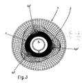
Figur 3- Tragring und Welle in Ansicht und z.T. geschnitten, mit Paßsitz als Gleichdick mit ca. 1,7 mm Abweichung von der Kreisform, im Wärmeschaubild.
- FIG. 1
- a support ring in view with cut shaft and mating surfaces of a weak Gleichdicks, in the mounted initial state
- FIG. 2
- the support ring of Figure 1 in the operating condition after heating.
- FIG. 3
- Support ring and shaft in view and partially cut, with snug fit as equal thickness with about 1.7 mm deviation from the circular shape, in the heat chart.
Fig. 1 zeigt den Tragring 7 mit geschnittener Welle 3 im montierten Ausgangszustand mit Paßsitz 6 mit einer geringfügigen Abweichung eines Polygonprofils von der Kreisform von einigen Millimetern. Es handelt sich hierbei um ein sogenanntes schwaches "Gleichdick".Fig. 1 shows the
Die Welle 3 weist in ihrem röhrenförmigen Hohlraum einen zentralen Kühlmittelkanal 4, und einen peripheren Kühlmittel-Ringkanal 5 auf.The
Fig. 2 zeigt den Tragring 7 mit der geschnittenen Welle 3 im Betriebszustand unter Last durch Torsionsbeanspruchung, sowie im erwärmten Zustand.Fig. 2 shows the
Die bevorzugte Ausgestaltung des Gleichdicks sieht dabei vor, dass die Abweichung der Paßflächen 6, 6' vom Idealrund, der Kreisform, einer Selbsthemmung bei einer Drehmomentübertragung zwischen Tragring 7 und Welle 3 entspricht. Diese Abweichung der Paßflächen 6, 6' vom Idealrund kann - je nach Ausführung und Beanspruchung in mechanischer und/oder thermischer Art - ca. 1 bis 5 mm betragen.The preferred embodiment of the same thickness provides that the deviation of the mating surfaces 6, 6 'from the ideal round, the circular shape, a self-locking in a torque transmission between the
Der Tragring 7 ist über Gleichdick-Passungstoleranzen 6, 6' rein mechanisch auf die Welle 3 aufgeschoben und durch relative Verdrehung mit der Welle 3 verklemmt, wobei die Befestigung des Tragringes 7 auf der Welle 3 nach dem Prinzip der Oberflächenvergrößerung durch Deformation der Kontaktflächen 6, 6' erfolgt.The
Zumindest soll die Abweichung der Paßflächen 6, 6' vom Idealrund geringfügig größer sein als die Wärmedehnung des Innendurchmessers der Aufnahmebohrung 1 des Tragringes 7 beim Betrieb des Ofens. Diese Aufnahmebohrung 1 bildet dabei die innere Kontaktfläche 6 mit der Gegenfläche 6' der Welle 3.At least the deviation of the mating surfaces 6, 6 'from Idealrund should be slightly larger than the thermal expansion of the inner diameter of the receiving bore 1 of the
Weiter sieht die Erfindung vor, dass der metallische Kontakt über das Gleichdick entweder über die gesamte Breite der Ofenrolle oder über deren Teilbereiche hergestellt ist. Der Tragring 7 kann ein- oder mehrstückig sein, bzw. aus Einzelringen hergestellt sein.Next, the invention provides that the metallic contact is made over the same thickness either over the entire width of the furnace roll or over their sub-areas. The
Bei der Herstellung der Ofenrolle können zwischen Tragring 7 und Welle 3, insbesondere bei dessen mehrteiliger Ausbildung, dünne Beilagen, bspw. aus Silberfolie oder Folie eines widerstandsfähigen und hochwärmeleitfähigen Metalls wie z.B. CuNiBe, eingelegt sein.In the manufacture of the furnace roller thin inserts, for example. From silver foil between
Fig. 3 zeigt eine Ausgestaltung der Erfindung, wonach das als Polygonprofil mit konstantem Durchmesser ausgebildete Gleichdick so schwache Passungstoleranzen zwischen den Kontaktflächen am Innendurchmesser des Tragringes 7 und dem Außendurchmesser der Welle 3 aufweist, dass eine Verdrehung von Tragring 7 und Welle 3 infolge der Übertragung eines Drehmomentes zu einer vergleichsweise großen elastisch-plastischen Deformation führt.Fig. 3 shows an embodiment of the invention, according to which formed as a polygon profile with constant diameter equal thickness so weak fitting tolerances between the contact surfaces on the inner diameter of the
An den Deformationsbereichen 6, 6' herrschen optimale metallische Kontakte mit idealen Wärmeleitungsbedingungen, und ermöglichen einen ungehinderten Wäre mefluß aus den Tragringen 7 in die Welle 3, wie dies aus dem Wärmeschaubild der Figur 3 erkennbar ist.At the
Claims (8)
- Water-coolable furnace roller for conveying transport stock, for example cast strip material of a continuous casting plant, through a roller hearth heating-up furnace, comprising a shaft (3), which is drivable in rotation and mounted outside the furnace, particularly with internally disposed coolant channels (4, 5), and with carrier rings (7) which are arranged on the shaft (3) by means of a receiving bore (1) and which form a conveying plane, characterised in that the contact surfaces at the internal diameter of the receiving bore (1) of the support ring (7) and/or at the external diameter of the shaft (3) are formed in the form of a polygonal profile with fit surfaces (6, 6') of approximately constant diameter as a so-called weak orbiform curve.
- Furnace roller according to claim 1, characterised in that the deviation of the fit surfaces (6, 6') from ideal roundness, the circular form, corresponds with a self-locking in the case of torque transmission between carrier ring (7) and shaft (3).
- Furnace roller according to claim 1 or 2, characterised in that the deviation of the fit surfaces (6, 6') from ideal roundness is approximately 4 to 5%.
- Furnace roller according to one or more of claims 1 to 3, characterised in that the deviation of the fit surfaces (6, 6') from ideal roundness corresponds at least with the amount of thermal expansion of the internal diameter of the receiving bore (1) of the carrier ring (7) during operation of the furnace.
- Furnace roller according to one or more of claims 1 to 4, characterised in that the metallic contact is produced by way of the orbiform curve either over the entire width of the furnace roller or over part regions thereof.
- Furnace roller according to one or more of claims 1 to 5, characterised in that the carrier ring (7) is of single-part or multi-part construction or produced from individual rings.
- Furnace roller according to one or more of claims 1 to 6, characterised in that thin shims, for example of silver foil or foil of a wear-resistant and highly heat conductive metal, such as, for example, CuNiBe, are inserted between carrier ring (7) and shaft (3).
- Furnace roller according to one or more of claims 1 to 7, characterised in that the orbiform curve formed as a polygon profile with constant diameter has such weak fit tolerances between the contact surfaces at the internal diameter of the receiving bore (1) of the carrier ring (7) and the outer diameter of the shaft (3) that twisting of carrier ring (7) and shaft (3) as a consequence of transmission of a torque leads to a comparatively substantial elastic-plastic deformation.
Applications Claiming Priority (2)
| Application Number | Priority Date | Filing Date | Title |
|---|---|---|---|
| DE10045251A DE10045251A1 (en) | 2000-09-13 | 2000-09-13 | Water-cooled furnace roller for conveying, for example, continuous casting workpieces through a roller hearth furnace |
| DE10045251 | 2000-09-13 |
Publications (2)
| Publication Number | Publication Date |
|---|---|
| EP1189004A1 EP1189004A1 (en) | 2002-03-20 |
| EP1189004B1 true EP1189004B1 (en) | 2006-12-13 |
Family
ID=7656043
Family Applications (1)
| Application Number | Title | Priority Date | Filing Date |
|---|---|---|---|
| EP01119488A Expired - Lifetime EP1189004B1 (en) | 2000-09-13 | 2001-08-14 | Water cooled furnace roller |
Country Status (5)
| Country | Link |
|---|---|
| US (1) | US6547557B2 (en) |
| EP (1) | EP1189004B1 (en) |
| JP (1) | JP5170924B2 (en) |
| AT (1) | ATE348307T1 (en) |
| DE (2) | DE10045251A1 (en) |
Families Citing this family (1)
| Publication number | Priority date | Publication date | Assignee | Title |
|---|---|---|---|---|
| CN108607788A (en) * | 2018-05-20 | 2018-10-02 | 苏州锌富化工有限公司 | A kind of roller heating device |
Family Cites Families (14)
| Publication number | Priority date | Publication date | Assignee | Title |
|---|---|---|---|---|
| GB317433A (en) * | 1928-08-16 | 1929-08-16 | Int Nickel Co | Improvements in or relating to carrier wheel devices |
| JPS522369B2 (en) * | 1971-08-20 | 1977-01-21 | ||
| DE2413270C2 (en) * | 1974-03-20 | 1975-08-21 | Ludwig-Ofag-Indugas Industrieofenanlagen Gmbh, 4300 Essen | Cooled oven transport roller |
| JPS5596236A (en) * | 1979-01-12 | 1980-07-22 | Kubota Ltd | Preparation of compound roll for continuous casting |
| JPS5759237Y2 (en) * | 1979-01-20 | 1982-12-17 | ||
| JPS6121162Y2 (en) * | 1980-08-11 | 1986-06-25 | ||
| US4991276A (en) | 1989-07-31 | 1991-02-12 | Bricmanage, Inc. | Flexible conveyance and guidance roller for use in metalworking furnace structures |
| DE4142941A1 (en) * | 1991-12-24 | 1993-07-01 | Kabelmetal Ag | USE OF A CURABLE copper alloy |
| US5230618A (en) * | 1992-02-24 | 1993-07-27 | Bricmanage, Inc. | Insulated furnace roller |
| US5362230A (en) * | 1993-03-24 | 1994-11-08 | Italimpianti Of America, Inc. | Rolls for high temperature roller hearth furnaces |
| US5370530A (en) * | 1993-03-24 | 1994-12-06 | Italimpianti Of America, Inc. | Rolls for high temperature roller hearth furnaces |
| JPH10181835A (en) * | 1996-12-27 | 1998-07-07 | Kubota Corp | Divisible tire roller |
| JP3678899B2 (en) * | 1998-01-29 | 2005-08-03 | 株式会社クボタ | Slab transfer roller |
| DE10012940A1 (en) * | 2000-03-16 | 2001-09-20 | Loi Thermprocess Gmbh | Disc roller for roller hearth furnace includes circumferentially-spaced rounded elevations in its supporting sections, which engage carrier ring depressions |
-
2000
- 2000-09-13 DE DE10045251A patent/DE10045251A1/en not_active Withdrawn
-
2001
- 2001-08-14 DE DE50111623T patent/DE50111623D1/en not_active Expired - Lifetime
- 2001-08-14 AT AT01119488T patent/ATE348307T1/en active
- 2001-08-14 EP EP01119488A patent/EP1189004B1/en not_active Expired - Lifetime
- 2001-09-07 JP JP2001272271A patent/JP5170924B2/en not_active Expired - Fee Related
- 2001-09-13 US US09/952,025 patent/US6547557B2/en not_active Expired - Fee Related
Also Published As
| Publication number | Publication date |
|---|---|
| US6547557B2 (en) | 2003-04-15 |
| ATE348307T1 (en) | 2007-01-15 |
| JP2002172453A (en) | 2002-06-18 |
| JP5170924B2 (en) | 2013-03-27 |
| DE50111623D1 (en) | 2007-01-25 |
| DE10045251A1 (en) | 2002-03-21 |
| US20020048740A1 (en) | 2002-04-25 |
| EP1189004A1 (en) | 2002-03-20 |
Similar Documents
| Publication | Publication Date | Title |
|---|---|---|
| EP1197721B1 (en) | Cooled furnace roller, in particular for a roller hearth furnace | |
| EP1397522B1 (en) | Roller table roll, particularly for conveying furnace-heated metallic strip material | |
| EP1937430B1 (en) | Strand guide reel | |
| EP1646463B1 (en) | Internally cooled billet guiding roller | |
| DE4022768C2 (en) | Roller conveyor roller and its use | |
| DE3152783C2 (en) | Roller for high temperature applications | |
| DE69024616T2 (en) | Cylinder for single or double roll caster | |
| WO2011026957A1 (en) | Roll and roll arrangement for a continuous casting installation | |
| WO2004039588A1 (en) | Rotative body of a printing press comprising a roll face | |
| EP0037549B1 (en) | Coaxial adjacent supported strand guiding rollers in a continuous casting plant for steel | |
| DE2216982A1 (en) | ARRANGEMENT FOR FASTENING A RING RING ON THE SURFACE OF A ROTATING TUBE, IN PARTICULAR A ROTATING TUBE FURNACE | |
| DE4041217A1 (en) | Driven roller for continuous heating furnace - has core tube enclosed in removable layer of thermal insulation | |
| EP1189004B1 (en) | Water cooled furnace roller | |
| DE3704744A1 (en) | TRANSPORT ROLL FOR GLASS COOLING CHANNELS | |
| DE10007383B4 (en) | Water-cooled oven roll for conveying workpieces through a reheating oven | |
| WO2005102558A2 (en) | Installation for treating continuously cast bars or continuously cast billets | |
| EP1940572B1 (en) | Strand guiding roller | |
| DE3515856C1 (en) | Tunnel-shaped industrial furnace | |
| EP1134531B1 (en) | Disk roller for a roller hearth furnace | |
| EP0331937B1 (en) | Roll hearth furnace for heating slabs, ingots, billets, metal sheets and similar materials | |
| DE4005900A1 (en) | DISC ROLLER FOR ROLLER OVENS | |
| DE10250690A1 (en) | Rotary body of a printing press with a bale | |
| DE10104032A1 (en) | Bearing arrangement used in galvanizing lines or in continuous casting plants comprises a bearing consisting of an inner bearing ring and an outer bearing ring, and a complete assembly with roller bodies arranged between the rings | |
| DE2734230C2 (en) | Outlets of a rotary kiln in satellite cooler tubes | |
| EP1032716B1 (en) | Coil box oven |
Legal Events
| Date | Code | Title | Description |
|---|---|---|---|
| PUAI | Public reference made under article 153(3) epc to a published international application that has entered the european phase |
Free format text: ORIGINAL CODE: 0009012 |
|
| 17P | Request for examination filed |
Effective date: 20010814 |
|
| AK | Designated contracting states |
Kind code of ref document: A1 Designated state(s): AT BE CH CY DE DK ES FI FR GB GR IE IT LI LU MC NL PT SE TR |
|
| AX | Request for extension of the european patent |
Free format text: AL;LT;LV;MK;RO;SI |
|
| AKX | Designation fees paid |
Free format text: AT BE CH CY DE DK ES FI FR GB GR IE IT LI LU MC NL PT SE TR |
|
| 17Q | First examination report despatched |
Effective date: 20050402 |
|
| GRAP | Despatch of communication of intention to grant a patent |
Free format text: ORIGINAL CODE: EPIDOSNIGR1 |
|
| GRAS | Grant fee paid |
Free format text: ORIGINAL CODE: EPIDOSNIGR3 |
|
| RBV | Designated contracting states (corrected) |
Designated state(s): AT BE CH DE DK ES FI FR GB GR IE IT LI LU NL PT SE TR |
|
| GRAA | (expected) grant |
Free format text: ORIGINAL CODE: 0009210 |
|
| AK | Designated contracting states |
Kind code of ref document: B1 Designated state(s): AT BE CH DE DK ES FI FR GB GR IE IT LI LU NL PT SE TR |
|
| PG25 | Lapsed in a contracting state [announced via postgrant information from national office to epo] |
Ref country code: FI Free format text: LAPSE BECAUSE OF FAILURE TO SUBMIT A TRANSLATION OF THE DESCRIPTION OR TO PAY THE FEE WITHIN THE PRESCRIBED TIME-LIMIT Effective date: 20061213 Ref country code: IE Free format text: LAPSE BECAUSE OF FAILURE TO SUBMIT A TRANSLATION OF THE DESCRIPTION OR TO PAY THE FEE WITHIN THE PRESCRIBED TIME-LIMIT Effective date: 20061213 Ref country code: DK Free format text: LAPSE BECAUSE OF FAILURE TO SUBMIT A TRANSLATION OF THE DESCRIPTION OR TO PAY THE FEE WITHIN THE PRESCRIBED TIME-LIMIT Effective date: 20061213 Ref country code: NL Free format text: LAPSE BECAUSE OF FAILURE TO SUBMIT A TRANSLATION OF THE DESCRIPTION OR TO PAY THE FEE WITHIN THE PRESCRIBED TIME-LIMIT Effective date: 20061213 |
|
| REG | Reference to a national code |
Ref country code: GB Ref legal event code: FG4D Free format text: NOT ENGLISH |
|
| REG | Reference to a national code |
Ref country code: CH Ref legal event code: EP |
|
| REG | Reference to a national code |
Ref country code: IE Ref legal event code: FG4D Free format text: LANGUAGE OF EP DOCUMENT: GERMAN |
|
| REF | Corresponds to: |
Ref document number: 50111623 Country of ref document: DE Date of ref document: 20070125 Kind code of ref document: P |
|
| PG25 | Lapsed in a contracting state [announced via postgrant information from national office to epo] |
Ref country code: SE Free format text: LAPSE BECAUSE OF FAILURE TO SUBMIT A TRANSLATION OF THE DESCRIPTION OR TO PAY THE FEE WITHIN THE PRESCRIBED TIME-LIMIT Effective date: 20070313 |
|
| PG25 | Lapsed in a contracting state [announced via postgrant information from national office to epo] |
Ref country code: ES Free format text: LAPSE BECAUSE OF FAILURE TO SUBMIT A TRANSLATION OF THE DESCRIPTION OR TO PAY THE FEE WITHIN THE PRESCRIBED TIME-LIMIT Effective date: 20070324 |
|
| GBT | Gb: translation of ep patent filed (gb section 77(6)(a)/1977) |
Effective date: 20070321 |
|
| ET | Fr: translation filed | ||
| PG25 | Lapsed in a contracting state [announced via postgrant information from national office to epo] |
Ref country code: PT Free format text: LAPSE BECAUSE OF FAILURE TO SUBMIT A TRANSLATION OF THE DESCRIPTION OR TO PAY THE FEE WITHIN THE PRESCRIBED TIME-LIMIT Effective date: 20070514 |
|
| NLV1 | Nl: lapsed or annulled due to failure to fulfill the requirements of art. 29p and 29m of the patents act | ||
| PLBE | No opposition filed within time limit |
Free format text: ORIGINAL CODE: 0009261 |
|
| STAA | Information on the status of an ep patent application or granted ep patent |
Free format text: STATUS: NO OPPOSITION FILED WITHIN TIME LIMIT |
|
| 26N | No opposition filed |
Effective date: 20070914 |
|
| BERE | Be: lapsed |
Owner name: SMS DEMAG AG Effective date: 20070831 |
|
| REG | Reference to a national code |
Ref country code: CH Ref legal event code: PL |
|
| PG25 | Lapsed in a contracting state [announced via postgrant information from national office to epo] |
Ref country code: CH Free format text: LAPSE BECAUSE OF NON-PAYMENT OF DUE FEES Effective date: 20070831 Ref country code: GR Free format text: LAPSE BECAUSE OF FAILURE TO SUBMIT A TRANSLATION OF THE DESCRIPTION OR TO PAY THE FEE WITHIN THE PRESCRIBED TIME-LIMIT Effective date: 20070314 Ref country code: LI Free format text: LAPSE BECAUSE OF NON-PAYMENT OF DUE FEES Effective date: 20070831 |
|
| PG25 | Lapsed in a contracting state [announced via postgrant information from national office to epo] |
Ref country code: BE Free format text: LAPSE BECAUSE OF NON-PAYMENT OF DUE FEES Effective date: 20070831 |
|
| PG25 | Lapsed in a contracting state [announced via postgrant information from national office to epo] |
Ref country code: LU Free format text: LAPSE BECAUSE OF NON-PAYMENT OF DUE FEES Effective date: 20070814 |
|
| PG25 | Lapsed in a contracting state [announced via postgrant information from national office to epo] |
Ref country code: TR Free format text: LAPSE BECAUSE OF FAILURE TO SUBMIT A TRANSLATION OF THE DESCRIPTION OR TO PAY THE FEE WITHIN THE PRESCRIBED TIME-LIMIT Effective date: 20061213 |
|
| PGFP | Annual fee paid to national office [announced via postgrant information from national office to epo] |
Ref country code: GB Payment date: 20120821 Year of fee payment: 12 |
|
| PGFP | Annual fee paid to national office [announced via postgrant information from national office to epo] |
Ref country code: FR Payment date: 20120906 Year of fee payment: 12 Ref country code: IT Payment date: 20120822 Year of fee payment: 12 Ref country code: DE Payment date: 20120822 Year of fee payment: 12 |
|
| PGFP | Annual fee paid to national office [announced via postgrant information from national office to epo] |
Ref country code: AT Payment date: 20120813 Year of fee payment: 12 |
|
| REG | Reference to a national code |
Ref country code: DE Ref legal event code: R119 Ref document number: 50111623 Country of ref document: DE |
|
| REG | Reference to a national code |
Ref country code: AT Ref legal event code: MM01 Ref document number: 348307 Country of ref document: AT Kind code of ref document: T Effective date: 20130814 |
|
| GBPC | Gb: european patent ceased through non-payment of renewal fee |
Effective date: 20130814 |
|
| REG | Reference to a national code |
Ref country code: FR Ref legal event code: ST Effective date: 20140430 |
|
| PG25 | Lapsed in a contracting state [announced via postgrant information from national office to epo] |
Ref country code: AT Free format text: LAPSE BECAUSE OF NON-PAYMENT OF DUE FEES Effective date: 20130814 Ref country code: IT Free format text: LAPSE BECAUSE OF NON-PAYMENT OF DUE FEES Effective date: 20130814 |
|
| PG25 | Lapsed in a contracting state [announced via postgrant information from national office to epo] |
Ref country code: GB Free format text: LAPSE BECAUSE OF NON-PAYMENT OF DUE FEES Effective date: 20130814 |
|
| PG25 | Lapsed in a contracting state [announced via postgrant information from national office to epo] |
Ref country code: FR Free format text: LAPSE BECAUSE OF NON-PAYMENT OF DUE FEES Effective date: 20130902 |
|
| REG | Reference to a national code |
Ref country code: DE Ref legal event code: R119 Ref document number: 50111623 Country of ref document: DE Effective date: 20140301 |
|
| PG25 | Lapsed in a contracting state [announced via postgrant information from national office to epo] |
Ref country code: DE Free format text: LAPSE BECAUSE OF NON-PAYMENT OF DUE FEES Effective date: 20140301 |