EP1187286A2 - Kabelhalter für Stromverteiler - Google Patents
Kabelhalter für Stromverteiler Download PDFInfo
- Publication number
- EP1187286A2 EP1187286A2 EP01118079A EP01118079A EP1187286A2 EP 1187286 A2 EP1187286 A2 EP 1187286A2 EP 01118079 A EP01118079 A EP 01118079A EP 01118079 A EP01118079 A EP 01118079A EP 1187286 A2 EP1187286 A2 EP 1187286A2
- Authority
- EP
- European Patent Office
- Prior art keywords
- cable holder
- plug
- holding element
- holder according
- connecting piece
- Prior art date
- Legal status (The legal status is an assumption and is not a legal conclusion. Google has not performed a legal analysis and makes no representation as to the accuracy of the status listed.)
- Granted
Links
Images


Classifications
-
- H—ELECTRICITY
- H02—GENERATION; CONVERSION OR DISTRIBUTION OF ELECTRIC POWER
- H02G—INSTALLATION OF ELECTRIC CABLES OR LINES, OR OF COMBINED OPTICAL AND ELECTRIC CABLES OR LINES
- H02G3/00—Installations of electric cables or lines or protective tubing therefor in or on buildings, equivalent structures or vehicles
- H02G3/30—Installations of cables or lines on walls, floors or ceilings
Definitions
- the invention relates to a cable holder for power distributors, with an eyelet or bracket-like Holding element which can be attached to a component of the distributor via a connecting piece.
- Such cable holders are preferably provided with the device carrier rails having a hat profile, e.g. for modular devices, connected and used in the distributors for mounting mainly from cables that run parallel to the equipment rack extend.
- the present invention has for its object an improved cable holder to create the kind mentioned above, which is compared to conventional cable holders can be installed in a power distributor at reduced cost.
- the cable holder according to the invention solving this problem is characterized by a Plug connection between the holding element and the connecting piece.
- This inventive solution advantageously reduces the mounting of the holding element the connector on a mating process.
- the holding element comprises a U-shaped holding part and from at least one of the U-legs there is a plug connection element on the outside, preferably a nose.
- the connector is preferably elongated with a connector element one end, preferably a plug hole opening to an end face, is formed.
- plug-in holes can be used to establish the plug connection or / and lugs may be provided so that the holding element in a distribution box in different depths can be placed.
- the connectors and holding elements can be in different, the grid dimensions dimensions of distributors are available.
- the plug nose tapers in cross section and is preferably graded in the direction of insertion.
- a graduated pin can also be used advantageously to the holding element without a connector e.g. to be attached to a support frame rail of a distributor.
- the pin is preferably at the free end, forming flexible fork legs slotted. These legs then give in when inserted into the plug hole.
- a plug nose having at least one latching lug at its free end be provided, preferably on a resilient formed by a slot Leg. So the legs can give way during the insertion process until the latch snaps into a recess within the plug hole.
- a slot with a continuous, the accessibility of the locked is useful Nose formed from the outside ensuring the recess.
- Loosen the plug / snap connection on the locking lugs a pressure can be exerted so that the Detent can be canceled and the tab can be pulled out of the hole.
- it is even possible to use such a hook-shaped latch which opens the plug-in / snap-in connection simply by exerting a pulling force on the pin would allow.
- the holding element with respect to a Level in which there is an opening slot for the insertion of cables and which the U-web of the Holding element intersects vertically be asymmetrical and on opposite Side latches.
- a cable holder for power distributors with a holding element comprising a U-shaped holding part, which is connected via a connecting piece is attachable to a component of the distributor, provided, at least one of the U-legs of the U-shaped holding part a device for connecting Holding element and connector, preferably a connector element, formed is.
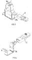
- the reference numeral 1 denotes an eyelet-like holding element of a cable holder in FIG. 1.
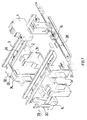
- the reference number 2 indicates a connecting piece via which the holding element, as shown in Fig. 7, e.g. on a device carrier rail 3 with a hat profile a distributor can be attached.
- On the device carrier rail 3 is exemplary in Fig. 7 a circuit breaker 4 attached.
- the holding element is formed with an insertion slot 5 for cables, the insertion slot being inclined to form a trough Leg sections of the holding element 1 is limited.
- the reference numeral 6 is movably connected to the holding element 1 Locking tab designated, with two locking lugs 7 for locking engagement in a through opening 8 is provided in the holding element 1.
- the eyelet-like holding element 1 has one U-shaped section 9, which is opposite the insertion slot 5.
- the holding element 1 is reinforced over part of the adjoining U-legs, with recesses 10 to avoid material accumulation of the holding element serve plastic material. From opposite inner surfaces of the U-legs protrude like dividers 11 inclined to each other, which the to Insert cables into the space available in the holding element.
- a plate-like plug lug 12 is formed on one of the U legs of the holding element 1, which is graduated in the exemplary embodiment shown and in its to the holding element 1 adjacent section with larger plate thickness recesses 13 to avoid Has material clusters.
- the lug 12 has locking lugs 14 Mistake. In the area of the locking lugs 14, the lug is through to the free end surface and Side surfaces opening slits 15 weakened, so that resilient, resilient Fork legs are formed.
- the reference numeral 16 indicates through holes in the Pin 12 with different diameters.
- the elongated connector 2 bent at 17 points towards an end face opening slot 18 for the lug 12 with the insertion of the lug facilitating Bevels 19 on the opening edge.
- the reference numeral 21 denotes two openings opening into the plug hole 18, which serve as locking recesses for the locking lugs 14.
- the reference numeral 22 recesses are designated to avoid the accumulation of material serve on the connector 2.
- the reference numeral 23 indicates one undercut mounting star, which in correspondingly shaped openings in the Device support rail 3 (Fig. 7) can be inserted and has four wings, the connector 2 facing sides are arched.
- the holding element 1 is then on the connector 2 attached, the tab 12 is inserted into the plug hole 18.
- the bevels 19 facilitate insertion.
- the compliant formed by the slots 15 Fork legs at the front end of the nose 12 are when inserted in the hole 18 is initially compressed by the ramps 25.
- the Lugs 14 in the openings 21 then widen again.
- the reinforced part of the plug nose facing the holding element 1 ensures high stability of the plug connection in terms of lateral forces, while the thinner end with those in the breakthroughs 21 protruding latches above all ensures that the connector is not Easily release a pulling force.
- a lever tool can be inserted into the recess 20 to release the plug connection become.
- the locking lugs 14 are accessible through the openings 21, so that a bend through the slots 15 formed by a suitable tool flexible fork leg can be done, thereby releasing the plug / snap connection is then relieved or even made possible by exerting a tractive force.
- the cable holder shown in FIGS. 2 to 4 use this on the basis of the exemplary embodiment 1 described connector and differ from the embodiment of Fig. 1 only in relation to the design of the holding element, the Pin 12 is largely excluded from these differences.
- a holding element 1a is used, the opposite the holding element 1 of the embodiment of Fig. 1 in the insertion direction of the cable is extended.
- a bead 27 is formed at one end of a U-leg or the U-web, which when attaching the holding element (without the connector) to one Scaffold rail 28 of a distributor serves as a guide (Fig. 7), the scaffold rail 28 between the locking lug 12 and the bead 27 against the U-leg of the holding element 1a comes to the plant.
- a holding element 1b in Fig. 3 is towards an insertion slot 5b by cranking the U-leg narrowed. It would also be conceivable to use only one cranked holding element U-legs, a straight U-leg and lugs on both U-legs. With different dimensions of the distance between the device carrier rails a distributor can, depending on the choice of the lug used, the insertion slot of the holding element can be arranged in the middle between the device carrier rails.
- a holding element 1c is only bow-shaped for the Inclusion of a wiring channel 29 with slots 30 through which cables from the Channel can be led out laterally, formed (Fig. 7).
- FIG. 6 is a connector 2d of a support member shows that via a star corresponding to the mounting star 23d 23d on a Device support rail 3d, which has a hat profile, is attached.
- the connector 2d with two optional plug holes 18d and 18d 'formed so that mounting elements within a junction box can be arranged at different depths.
- the holes 18d and 18d ' are formed on the inside like the plug hole 18 of the connecting piece 2.
- Corresponding also has an intermediate wall 31 between the plug holes 18d and 18d '(in FIG. 6 not visible) openings 21 d corresponding openings as recesses for the Engagement of locking lugs on.
- a closure part 32 can be provided for the holding elements, which has locking legs 33 on opposite sides, in the provided on the holding element Can snap latches 34.
Landscapes
- Engineering & Computer Science (AREA)
- Architecture (AREA)
- Civil Engineering (AREA)
- Structural Engineering (AREA)
- Connector Housings Or Holding Contact Members (AREA)
- Insertion, Bundling And Securing Of Wires For Electric Apparatuses (AREA)
- Manufacturing Of Electrical Connectors (AREA)
Abstract
Description
- Fig. 1
- einen Kabelhalter gemäß einem ersten Ausführungsbeispiel der Erfindung in einer perspektivischen Ansicht,
- Fig. 2
- einen Kabelhalter gemäß einem zweiten Ausführungsbeispiel der Erfindung in einer perspektivischen Ansicht,
- Fig. 3
- einen Kabelhalter gemäß einem dritten Ausführungsbeispiel der Erfindung in einer perspektivischen Ansicht,
- Fig. 4
- einen Kabelhalter gemäß einem vierten Ausführungsbeispiel der Erfindung in einer perspektivischen Ansicht,
- Fig. 5
- ein in den Kabelhaltern von Fig. 1 bis 4 verwendetes Verbindungsstück,
- Fig. 6
- ein weiteres Ausführungsbeispiel für ein in einem Kabelhalter nach der Erfindung verwendbares Verbindungsstück, und
- Fig. 7
- Bauteile eines Stromverteilers, an denen Kabelhalter gemäß der Erfindung angebracht sind.
Claims (12)
- Kabelhalter für Stromverteiler, mit einem ösen- oder bügelartigen Halteelement (1), das über ein Verbindungsstück (2) an einem Bauteil (3) des Verteilers anbringbar ist, gekennzeichnet durch eine Steckverbindung zwischen dem Halteelement (1) und dem Verbindungsstück (2).
- Kabelhalter nach Anspruch 1,
dadurch gekennzeichnet, daß zwischen dem Halteelement (1) und dem Verbindungsstück (2) eine einrastende Steckverbindung herstellbar ist. - Kabelhalter nach Anspruch 1 oder 2,
dadurch gekennzeichnet, daß das Halteelement (1) einen U-förmigen Halteteil (9) umfaßt, und von wenigstens einem der U-Schenkel des Halteteils (9) nach außen ein Steckverbindungselement, vorzugsweise eine Stecknase, vorsteht. - Kabelhalter nach einem der Ansprüche 1 bis 3,
dadurch gekennzeichnet, daß das Verbindungsstück (2) länglich mit einem Steckverbindungselement an einem Ende, vorzugsweise einem zu einer Endstirnfläche öffnenden Steckloch (18), ausgebildet ist. - Kabelhalter nach einem der Ansprüche 1 bis 4,
dadurch gekennzeichnet, daß zur Herstellung der Steckverbindung mehrere, wahlweise verwendbare Stecklöcher (18d,18d') oder/und Stecknasen vorgesehen sind. - Kabelhalter nach einem der Ansprüche 1 bis 5,
dadurch gekennzeichnet, daß eine sich im Querschnitt verjüngende, vorzugsweise in Steckrichtung abgestufte, Stecknase (12) und ein sich verengendes Steckloch vorgesehen sind. - Kabelhalter nach einem der Ansprüche 1 bis 6,
dadurch gekennzeichnet, daß eine unter Bildung nachgiebiger Gabelschenkel am freien Ende wenigstens einen Schlitz (15) aufweisende Stecknase (12) vorgesehen ist. - Kabelhalter nach einem der Ansprüche 1 bis 7,
dadurch gekennzeichnet, daß eine an ihrem freien Ende wenigstens eine Rastnase (14) aufweisende Stecknase (12) vorgesehen ist. - Kabelhalter nach einem der Ansprüche 1 bis 8,
dadurch gekennzeichnet, daß ein Steckloch (18) mit einer durchgehenden, die Zugänglichkeit der eingerasteten Rastnase (14) von außen gewährleistenden Rastausnehmung (21) gebildet ist. - Kabelhalter nach einem der Ansprüche 1 bis 9,
dadurch gekennzeichnet, daß ein Steckloch (18) mit einer Aussparung (20) am Öffnungsrand für den Eingriff eines zum Lösen der Steckverbindung verwendenden Werkzeugs gebildet ist. - Kabelhalter nach einem der Ansprüche 1 bis 10,
dadurch gekennzeichnet, daß das Halteelement in bezug auf eine Ebene, in welcher ein Öffnungsschlitz zum Einführen von Kabeln gelegen ist und die einen U-Steg des Halteelements senkrecht schneidet, unsymmetrisch ausgebildet ist. - Kabelhalter für Stromverteiler, mit einem einen U-förmigen Halteteil (9) umfassenden Halteelement (1), das über ein Verbindungsstück (2) an einem Bauteil (3) des Verteilers anbringbar ist,
dadurch gekennzeichnet, daß an wenigstens einem der U-Schenkel des U-förmigen Halteteils eine Einrichtung, vorzugsweise ein Steckverbindungselement (12), zur Verbindung von Halteelement (1) und Verbindungsstück (2) vorgesehen ist.
Applications Claiming Priority (2)
| Application Number | Priority Date | Filing Date | Title |
|---|---|---|---|
| DE20015119U DE20015119U1 (de) | 2000-08-31 | 2000-08-31 | Kabelhalter für Stromverteiler |
| DE20015119U | 2000-08-31 |
Publications (3)
| Publication Number | Publication Date |
|---|---|
| EP1187286A2 true EP1187286A2 (de) | 2002-03-13 |
| EP1187286A3 EP1187286A3 (de) | 2004-01-07 |
| EP1187286B1 EP1187286B1 (de) | 2007-06-06 |
Family
ID=7945932
Family Applications (1)
| Application Number | Title | Priority Date | Filing Date |
|---|---|---|---|
| EP20010118079 Expired - Lifetime EP1187286B1 (de) | 2000-08-31 | 2001-07-26 | Kabelhalter für Stromverteiler |
Country Status (2)
| Country | Link |
|---|---|
| EP (1) | EP1187286B1 (de) |
| DE (2) | DE20015119U1 (de) |
Cited By (2)
| Publication number | Priority date | Publication date | Assignee | Title |
|---|---|---|---|---|
| WO2004109883A1 (de) * | 2003-06-07 | 2004-12-16 | Hager Electro Gmbh | Kleinverteiler |
| FR2979758A1 (fr) * | 2011-09-06 | 2013-03-08 | Schneider Electric Ind Sas | Dispositif de rangement des conducteurs de cablage des appareillages dans une armoire electrique equipee de rails de montage desdits appareillages |
Family Cites Families (5)
| Publication number | Priority date | Publication date | Assignee | Title |
|---|---|---|---|---|
| FR2300290A1 (fr) * | 1975-02-07 | 1976-09-03 | Itt Produits Ind | Support encliquetable sur rail normalise |
| DE2843858A1 (de) * | 1978-10-07 | 1980-04-17 | Bbc Brown Boveri & Cie | Sammelschienensystem zum anschliessen von elektrischen installationseinbaugeraeten |
| GB2247351B (en) * | 1990-08-21 | 1995-03-01 | Crabtree Electrical Ind Ltd | Improvements relating to the mounting of circuit breakers |
| FR2692412B1 (fr) * | 1992-06-15 | 1994-09-02 | Merlin Gerin | Goulotte pour dispositif de distribution électrique. |
| DE29606911U1 (de) * | 1996-04-17 | 1996-07-04 | Elinnovation i Ange AB, Ange | Vorrichtung zum Zusammenbau von Ausrüstung |
-
2000
- 2000-08-31 DE DE20015119U patent/DE20015119U1/de not_active Expired - Lifetime
-
2001
- 2001-07-26 DE DE50112590T patent/DE50112590D1/de not_active Expired - Lifetime
- 2001-07-26 EP EP20010118079 patent/EP1187286B1/de not_active Expired - Lifetime
Cited By (10)
| Publication number | Priority date | Publication date | Assignee | Title |
|---|---|---|---|---|
| WO2004109883A1 (de) * | 2003-06-07 | 2004-12-16 | Hager Electro Gmbh | Kleinverteiler |
| DE10325938B4 (de) * | 2003-06-07 | 2016-07-28 | Hager Electro Gmbh | Kleinverteiler |
| FR2979758A1 (fr) * | 2011-09-06 | 2013-03-08 | Schneider Electric Ind Sas | Dispositif de rangement des conducteurs de cablage des appareillages dans une armoire electrique equipee de rails de montage desdits appareillages |
| CN102983504A (zh) * | 2011-09-06 | 2013-03-20 | 施耐德电器工业公司 | 在配有导轨的电气柜中安置设备单元的布线导体的装置 |
| GB2505084A (en) * | 2011-09-06 | 2014-02-19 | Schneider Electric Ind Sas | Rail mounted cable management for a cabinet |
| ES2458916R1 (es) * | 2011-09-06 | 2014-05-19 | Schneider Electric Industries Sas | Dispositivo de ordenamiento de los conductores del cableado de los aparatos en un armario eléctrico equipado con carriles de montaje de dichos aparatos |
| GB2505084B (en) * | 2011-09-06 | 2014-11-19 | Schneider Electric Ind Sas | Device for managing the conductors of the cabling of the equipment in an electrical cabinet provided with rails for mounting said equipment |
| CN102983504B (zh) * | 2011-09-06 | 2016-08-17 | 施耐德电器工业公司 | 在配有导轨的电气柜中安置设备单元的布线导体的装置 |
| RU2597869C2 (ru) * | 2011-09-06 | 2016-09-20 | Шнейдер Электрик Эндюстри Сас | Устройство для размещения электрической проводки модулей оборудования в электрическом шкафу, оснащенном рейками для установки модулей указанного оборудования |
| DE102012025676B4 (de) | 2011-09-06 | 2025-02-06 | Schneider Electric Industries Sas | Vorrichtung zum Ordnen der Leiter der Verkabelung von Geräten in einem elektrischen, mit Montageschienen für die Geräte ausgestatteten Schaltschrank |
Also Published As
| Publication number | Publication date |
|---|---|
| DE50112590D1 (de) | 2007-07-19 |
| EP1187286B1 (de) | 2007-06-06 |
| DE20015119U1 (de) | 2002-01-17 |
| EP1187286A3 (de) | 2004-01-07 |
Similar Documents
| Publication | Publication Date | Title |
|---|---|---|
| DE69636873T2 (de) | Steckverbinder-Montagegehäuse | |
| DE3643559C2 (de) | In einem Brüstungskanal befestigbare Einbaudose | |
| EP3490075A1 (de) | Set aus steckverbinder und halteelement sowie steckverbinder und halteelement hierzu | |
| DE102023105747A1 (de) | Steckverbinder, Halteelement sowie Set aus einem Steckverbinder und einem Halteelement | |
| DE19945817C2 (de) | Sammelanschlußleiste | |
| DE4103957A1 (de) | Kabelkanal, wie installationskanal | |
| DE19615597B4 (de) | Vorrichtung zum Kontaktieren der Leiteradern von mehreren bandförmig verlaufenden bielektrischen Leitungen mit den Leiteradern von elektrischen Anschlußleitungen eines elektrischen Verbrauchers, insbesondere den Leuchten einer Schienenleuchte | |
| DE8660057U1 (de) | Versorgungs- und Verteilerkanal, insbesondere für elektrische Verbraucher und Kommunikationseinrichtungen. | |
| DE3885474T2 (de) | Baukastensystem zur Herstellung von Leitungen zur Aufnahme von elektrischen Kabeln und dergleichen. | |
| DE3925010C2 (de) | Kabelkanal | |
| WO2011157772A1 (de) | Reihenklemme | |
| DE10005219C2 (de) | Isoliergehäuse zur Befestigung an einer Tragschiene | |
| EP1187286B1 (de) | Kabelhalter für Stromverteiler | |
| EP0749180B1 (de) | Steckverbindergehäuse | |
| DE19638971A1 (de) | Relaissockel | |
| DE10005260C2 (de) | Isoliergehäuse für Verteilerklemme | |
| DE102017113811A1 (de) | Anordnung für einen Verteilerkasten | |
| DE10305931B4 (de) | Vorrichtung zur Befestigung von Bauteilen elektrischer Zähler- und Verteilereinrichtungen an einer Trägerschiene | |
| EP1359650B1 (de) | Anschlussvorrichtung für elektrische Verteiler | |
| EP1217693B1 (de) | Anschlussleiste | |
| DE10135662A1 (de) | Gerätebecherrahmen für Unterfluranwendungen | |
| EP1463170A2 (de) | Zähler- und/oder Verteilerschrank | |
| DE10065354A1 (de) | Steckverbinder für flexible Flachbandleiter | |
| DE102019101881B3 (de) | Rastvorrichtung, Steckverbinder und Verfahren zum Zusammenbau eines Steckverbinderteils | |
| DE9104428U1 (de) | Befestigungsvorrichtung für ein Gehäuse einer elektrischen Steckvorrichtung in einer Wandungsöffnung |
Legal Events
| Date | Code | Title | Description |
|---|---|---|---|
| PUAI | Public reference made under article 153(3) epc to a published international application that has entered the european phase |
Free format text: ORIGINAL CODE: 0009012 |
|
| AK | Designated contracting states |
Kind code of ref document: A2 Designated state(s): AT BE CH CY DE DK ES FI FR GB GR IE IT LI LU MC NL PT SE TR |
|
| AX | Request for extension of the european patent |
Free format text: AL;LT;LV;MK;RO;SI |
|
| PUAL | Search report despatched |
Free format text: ORIGINAL CODE: 0009013 |
|
| RIC1 | Information provided on ipc code assigned before grant |
Ipc: 7H 02G 3/30 A Ipc: 7H 02B 1/048 B Ipc: 7H 02B 1/20 B |
|
| AK | Designated contracting states |
Kind code of ref document: A3 Designated state(s): AT BE CH CY DE DK ES FI FR GB GR IE IT LI LU MC NL PT SE TR |
|
| AX | Request for extension of the european patent |
Extension state: AL LT LV MK RO SI |
|
| 17P | Request for examination filed |
Effective date: 20040630 |
|
| AKX | Designation fees paid |
Designated state(s): DE FR |
|
| 17Q | First examination report despatched |
Effective date: 20050509 |
|
| GRAP | Despatch of communication of intention to grant a patent |
Free format text: ORIGINAL CODE: EPIDOSNIGR1 |
|
| GRAS | Grant fee paid |
Free format text: ORIGINAL CODE: EPIDOSNIGR3 |
|
| GRAA | (expected) grant |
Free format text: ORIGINAL CODE: 0009210 |
|
| RAP1 | Party data changed (applicant data changed or rights of an application transferred) |
Owner name: HAGER ELECTRO GMBH & CO. KG |
|
| AK | Designated contracting states |
Kind code of ref document: B1 Designated state(s): DE FR |
|
| REF | Corresponds to: |
Ref document number: 50112590 Country of ref document: DE Date of ref document: 20070719 Kind code of ref document: P |
|
| ET | Fr: translation filed | ||
| PLBE | No opposition filed within time limit |
Free format text: ORIGINAL CODE: 0009261 |
|
| STAA | Information on the status of an ep patent application or granted ep patent |
Free format text: STATUS: NO OPPOSITION FILED WITHIN TIME LIMIT |
|
| 26N | No opposition filed |
Effective date: 20080307 |
|
| REG | Reference to a national code |
Ref country code: DE Ref legal event code: R082 Ref document number: 50112590 Country of ref document: DE Representative=s name: PATENTANWAELTE BERNHARDT/WOLFF PARTNERSCHAFT, DE Ref country code: DE Ref legal event code: R082 Ref document number: 50112590 Country of ref document: DE Representative=s name: CABINET NUSS, FR |
|
| REG | Reference to a national code |
Ref country code: DE Ref legal event code: R082 Ref document number: 50112590 Country of ref document: DE Representative=s name: CABINET NUSS, FR |
|
| REG | Reference to a national code |
Ref country code: FR Ref legal event code: PLFP Year of fee payment: 16 |
|
| REG | Reference to a national code |
Ref country code: FR Ref legal event code: PLFP Year of fee payment: 17 |
|
| REG | Reference to a national code |
Ref country code: FR Ref legal event code: PLFP Year of fee payment: 18 |
|
| PGFP | Annual fee paid to national office [announced via postgrant information from national office to epo] |
Ref country code: FR Payment date: 20180726 Year of fee payment: 18 Ref country code: DE Payment date: 20180727 Year of fee payment: 18 |
|
| REG | Reference to a national code |
Ref country code: DE Ref legal event code: R119 Ref document number: 50112590 Country of ref document: DE |
|
| PG25 | Lapsed in a contracting state [announced via postgrant information from national office to epo] |
Ref country code: DE Free format text: LAPSE BECAUSE OF NON-PAYMENT OF DUE FEES Effective date: 20200201 |
|
| PG25 | Lapsed in a contracting state [announced via postgrant information from national office to epo] |
Ref country code: FR Free format text: LAPSE BECAUSE OF NON-PAYMENT OF DUE FEES Effective date: 20190731 |